Note: Descriptions are shown in the official language in which they were submitted.
CA 02243815 1998-07-23
!'A TENT
Docket No. W INN.42293
IMPROVED HANDLE GRIP
Background of the Invention
'The present invention relates to an improved grip for golf clubs and other
sporting
equipment employing handles subject to shock when such devices are impacted,
as for example,
tennis racquets, racquetball racquets, and baseball bats.
It is well known that shock generated by impact between a golf club and a golf
ball or a
tennis racquet and a tennis ball can adversely affect muscle tissue and arm
joints, such as elbow
,joints. The energy generated by such impact is usually of high frequency and
short duration
with rapid decay, and which is often known as "impact shock." Tight grasping
of a golf club
I 0 grip or tennis racquet grip to keep it from slipping in a user's hand
contributes to such impact
shock.
Applicant has previously developed resilient grips which successfully
reduce or even eliminate impact shock to the muscle and arm joints of the
users of
golf clubs and the like. Such earlier grips utilize a polyurethane layer
bonded to a felt
l 5 layer to define a strip which is spirally wrapped around the handle of a
golf club or
tennis racquet to conform generally to the external configuration
CA 02243815 1998-07-23
PATENT
Docket No. If~INN..f1293
of such handle. In earlier gn-ips of applicant's design, the thickness of the
polyurethane layer
relative to the thickness of the felt layer as compared to prior ar-t
resilient grips was a
minimum of approximately 0.18, with the thickness of the polyurethane layer
having been
about equal to or thicker than the thickness of the textile layer in a typical
grip of my design.
Also, in some of such earlier- grips, the side edges of the polyurethane-felt
strip tended to
unravel in use, and where the strip was not properly applied to a golf club
handle, the grip
would tend to loosen relative to the handle, particularly, when a golf club
was withdrawn
from a golf club bag. To overcome these disadvantages, my later grip designs
utilized heat-
compressed radially inwardly extending reinforcement side edges formed in the
polyurethane
layer along the length of the strip. Tlre recessed side edges also enhance the
frictional grip
of a user's hands on the golf club or tennis racquet. Although my prior grips
provide
satisfactory results, under humid or rainy conditions water tended to
infiltrate the felt layer
causing moisture to build up on the gr7p wlriclr could result in a user's
hands slipping relative
to the grips with a result in diminished control of the golf club or tennis
racquet. Similarly,
I S perspiration moisture could also infiltrate the felt layer.
CA 02243815 1998-07-23
PATENT
Docket No. WINN.d229.?
Summary of the Invention
Applicant has discovered that polyurethane-felt grips of the aforedescribed
nature can
be made water retarding to per7rrit a user to continue playing even during
humid or rainy
conditions. Such improved snip utilizes applicant's previously developed
concept of bonded-
together layers of polyurethane and felt wherein the ratio of the thickness to
the thickness of
the felt layer is a minimum of approximately 0.18. The water retarding grip of
the present
invention utilizes heat-compressed sidewardly and outwardly curved
reinforcement side
edges along its length, but additionally, the underside of the felt layer is
skived to form
slanted side edges. The strip is spirally wrapped about a golf club or tennis
racquet handle
with the underside of the reinforcement side edges overlying the slanted side
edges of the felt
layer. An adhesive is provided on the underside of the felt layer to adhere
the strip to the
handle. The profile provided by the overlapped reinforced side edges enhances
the frictional
grip of a user's hands on a golf club or tennis racquet. The overlapped side
edges also
restrain unraveling from the ship from the handle, while retarding the
entrance of water
between the joints defined by the overlapped side edges of the ship.
Additionally, the
overlapping side edges provide an improved appearance over conventional grips.
In a
modified embodiment of a lnip embodying the present invention, the center of
the underside
of the felt layer of the ship is also skived to define an upwardly extending
groove in the
3
CA 02243815 1998-07-23
PATENT
Docket No. WINN.41193
lower por-rion of the stl7p. Vfhen the snip is spirally wrapped about the
handle of a golf club
or a tenors racquet, the groove produces a concave spirally extending
depression along the
length of the grip which cooperates with the pair of convex spirally extending
profiles
created by the slanted side edges to increase the surface area of the ~,~rip
engaged by the user's
hands to thereby afford additional control of a golf club or tennis racquet.
Additionally, the
appe~rrance of the grip is further enhanced, while the frictional contact of
the overlapping
joints of the staip behveen adjoining golf clubs in a golf bag is reduced to
thereby further
restrain unraveling of the strip from the golf club.
The polyurethane-felt strip o1~ the present invention may be spirally wrapped
about
a tapered resilient sleeve that has been applied to the handle of a golf club
shaft.
Alternatively, the ship may be directly spirally wrapped about the handle of a
golf club or
tennis racquet. The polyurethane-felt strip may also be spirally wrapped about
a tapered
sleeve while the sleeve is positioned on a collapsible mandrel to provide a
slip-on golf club
grip that can be applied to a new golf club or can be utilized as a
replacement golf grip.
t 5 In addition to the above advantages, the grip of the present invention has
been found
to greatly cushion the shock h~ansfeu-ed fi~orn a golf club to a golfer's body
or from a tennis
racquet to the arm of a tennis player, thereby preventing the danger of injury
to a user of the
4
CA 02243815 2004-02-06
grip. The grip can also provide a long service life, may be manufactured at a
low cost,
and can be readily installed by a user.
In a broad aspect, then, the present invention relates to the combination of a
handle of an impact imparting device and a resilient grip, such combination
comprising:
a strip consisting of a textile layer having a generally flat inner surface
and radially
extending side edges, and a plastic layer having its inner surface bonded to
the outer
surface of the textile layer, and with the textile layer providing strength
for the plastic
layer while the plastic layer both absorbs shocks and provides tackiness so as
to inhibit
slippage of a user's hand relative to the handle; an adhesive on the underside
of the
textile layer; radially inwardly extending reinforcement side edges formed in
the plastic
layer of the strip along the length of the strip; slanted side edges formed
along the length
of the textile layer; a resilient sleeve applied to the handle; and the strip
being spirally
wrapped about the sleeve to define said grip, with the underside of adjoining
recessed
side edges overlapping one another to define a water retarding joint between
the
adjoining side edges.
In another broad aspect, then, the present invention relates to a method of
making
a golf club grip, said method comprising: forming a strip consisting of a
textile layer
having a generally flat inner surface and a plastic layer having its inner
surface bonded
to the outer surface of the textile layer, and with the textile layer
providing strength for
the plastic layer while the plastic layer both absorbs shocks and provides
tackiness so as
to inhibit slippage of a user's hand relative to said handle; applying a
heated platen
radially inwardly against the side edges of the plastic layer with sufficient
pressure to
compress the material of the plastic radially inwardly of the upper surface of
such layer;
skiving the underside of the textile to form slanted side edges along the
length of the
textile layer; applying an adhesive to the underside of the textile layer;
providing a
resilient sleeve; and spirally wrapping the strip around the sleeve with the
slanted side
edges of the textile layer overlapping one another to form a water retarding
joint between
the adjoining side edges.
CA 02243815 2004-02-06
These and other features and advantages of the present invention will become
apparent from the following detailed description, when taken in conjunction
with the
accompanying drawings.
Brief Description of the Drawings
Fig. 1 is a top plan view of the polyurethane-felt strip member of a golf club
grip
embodying the present invention before the polyurethane layer is formed with
sidewardly
and outwardly curved reinforcement side edges and the felt layer is provided
with skived
side edges;
Fig. 2 is a top plan view showing a heated platen utilized to form sidewardly
and
outwardly curved reinforcement side edges in the polyurethane layer of the
strip of Fig.
l;
Sa
CA 02243815 2003-08-05
t ~~~ r,
.~-':~ t ,~,.: ,f y.
. .5 y y 5 a ~y~75;
%.~#3i;K~'.~.;si3. ate ~.~'~:'~..'--~'.:._..~
~'i~., ~s a ~ ~cz~:~~~~ r-~~;~~ a~~~~~~. ~v~: f3~'~'~~~. ~ aY~f.~ :~ L~~~~~
~vw '~:i~~:.~~:~.r~~.~~.' <~t~
IA°:: ~'.'';i<M',~~~ t3~~l~a)~' J?'~~.;:'~.~~it~~~ 3Y:' ;,''4i.i:~
~~.~~ ~:~'d~s~r',?is.'-, i9.,:3~~. ~~':~3~.I~~.tt. ~F1;~E t3~b'~, ~?a:~.fS
~clT?~'.'~~.~:,
... . . ., ~~ fi
~:'k#,~< ~ ~'L ~? F.~'i3Ei.~ii ~~>N 3_'r~ii,3~ b'~L.':'s~' R3~~ ie
S~~.fi.~:.f~;~ .~~~3? t';'. >ra~i'FErI'~:i.'~<.:,nsl'.1~'~.~~ i~'E'.~
~n SiSi.~::i.F~3~~. ~~~;xi:'~: ~~ ~~~.~r.'t:,r~Yf':~~. J~::~',r'ai
~~°~C~.~~~~i.'. ;.i.3 ~'~~.~:',.~.~e. ~ . :.,, en~.~i .~3..
~,~"1"~. > .S 3 ~.'.~'t~.a;~'~C?~3 ~:~.i'#.CF. ~'s~'~y (~.t~ 3 ~~~'~.:,~'6h
~<33"~? i:5' ~i:~l~ ~I~':~>fi~'~F1'r'~~'~ ly'~'~;'3~"~:
" f~
~?
~~~~i~~'~~1~ °~i:.~.~;s.,~';c~. S~:.z~~~~' ~'s~ i~,'t.~v~; ø.~;;
~':~":, I s ..., 'u'3'~~' _.,
i~~:, ~~.'i i, 'i;,'.f~.IL',~~, ~:;.'.i'I3<i~'slI :'k~.'i~"s.t3~,':~3 ls'~
~i.3.y~:i"':~',''L~S w.s.'~~ f.?<,)~~'' ~S.t3.3.~ .~ ,n 3j.~~ r, ..
., ... ~. " .:,. .' .
ry '? ~. >, m~.~,;-;~'S-,:;,:<a.,,~ ,:~r<r~r ' <7~' s;~r,.:<a >; ; 7 sa ..
;~~. ,,~_:
~~'..~,. ~r ;~: n ,.~..v~.."~.1 s~:~...~~~:~{A~~:l -a. ~.~:,~ Ur:~1~~.~~ .~.
;:~~ls~:~~..... ,.,,f~.<,,. t,~~.~x~. ~~r~~: ~-~ 3.:°:~ ~4..: .
~ ~z.y. : _;;, :,' i~r ..r~,a;: _ ;~.;a - f:e';,~c~;% ;,'ysa 7~wr.-r ~ .;; ,-'
y ~i~v., ~;. -SS>,.r.I5; ~:
:~~'~,,..:. #.~~.,~ a.~#.<t: ;:5. ~"~ i3~s~#'..3:, ~.':..: ~~.-r...3' .~.~:,.
.:.c.;..~~...~..~~;'~.'f~ ~ ) v..3:.i7. t.,l.l,a<lv.~... ,3i;~~
~ 'r...
~'s~si3v'~:%~~3' ;'~S<'3"si~.:~~s >'s3C~,"', '~,.''~~~;;, i~'"F~~S ~?.si
~E~~~?:w~'~.~it' ~:~s~~:'~ks#.:i ~3C~'";wi3 i:~.~~:%~'s'sa''.'~3S
~~,.~r'~.sif' I~#~%.CfLe,~is.t~.fi.'
;. :"~ 63 ~~ ~','"3c.'', ~t''.~ .~zi ~.' ~'~ ;
., ,, % , 4a.y ~~ r 1r, fi ~~i. 7.S.t ~~,i.:7 7
.~''r;f :; .s z~ s~5!'~~?',~~;.'':.1;. ffi~~~ ~5z;<;. 's'.~.: :' t.. ~. w~.x,.
:3:.i".~~? >J"S)ih 4 ~:'
f;
CA 02243815 1998-07-23
PATENT
Docket No. 6i~INN.41193
Fig. IO is a broken viecv of the underside of the starting strip shown in Fig.
3;
Fig. 11 is a vertical sectional view taken in enlarged scale along line I 1-11
of Fig. 10;
Fig. I2 is a perspective view of a first form of underlisting sleeve utilized
in an
embodiment of the present invention;
Fig. 13 is a side elevational view of the sleeve of Fig. 12;
Fig. 14 is a side elevational view of a second form of underlisting sleeve
rotated 90
degrees from the position shown in Fig. 13;
Fig. I5, IG, and 17 are side elevational views showing a third form of
underlisting
sleeve which may be utilized in forming a grip embodying the present
invention;
Fig. l8 is a broken side elevational view showing a polyurethane-felt ship
embodying
the present invention being spirally wrapped around the underlisting sleeves
of Figs. 12 and
I3 to form a grip embodying the present invention;
7
CA 02243815 1998-07-23
PATENT
Docket No. WINN.41293
Fig. 19 is a vertical sectional vew taken in enlwged scale along line 19-19 of
Fig. 18;
Fig. 20 is a fiu-ther enlarged vertical sectional view of the area designated
20 in Fig.
19;
Fig. 21 is a vertical sectional view showing a collapsible mandrel supporting
the
S underlisting sleeve of Figs. 12 and 13 while a polyurethane-felt ship
embodying the present
invention is wrapped around such underlisting sleeve;
Fig. 22 is a broken side perspective vew showing a golf club shaft adapted to
directly
rcccive a polyurethane-felt strip embodying the present invention;
Fig. 23 is a broken side elevational view showing a polyurethane-felt strip of
the
present invention being wrapped around the golf club shaft of Fig. 22;
Fig. 24 is a broken side elevational view of a cap applied to the upper end of
the golf
club shaft of Fig. 23;
8
CA 02243815 1998-07-23
PATENT
Docket No. WINN..11193
Fig. 25 is an enlarged velrtical sectional view showing a second form of cap
which
may be utilized with a grip embodying the present invention;
Fig. 26 is a perspective view of a golf club provided with a grip of the
present
invention;
Fig. 27 is a perspective view showing a grip of the present invention being
applied to
a tennis racquet;
Fig. 28 is a perspective view showing a grip of the present invention as
installed on
a tennis racquet;
Fig. 29 is a broken top plan view of a modified form of strip embodying the
present
invention wherein tl~e underside of the felt layer is formed with an upwardly
extending
groove;
Fig. 30 is a ve~fical sectional view taken in enlarged scale along line 30-30
of Fig. 29;
9
CA 02243815 1998-07-23
PATENT
Docket No. WINN.42293
Fig. 31 is a broken side elevational view showing the strip of Figs. 29 and 30
being
spirally wrapped about a golf club handle;
Fig. 32 is a vertical sectional view taken in enlarged scale along line 32-32
of Fig. 31;
and
Fig. 33 is a perspective vew of the modified form of the ~,n-ip spirally
wrapped around
a tennis racquet handle.
Detailed Description of Prefer7~ed Embodiments
Rcfen-ing to the drawings, a prcfcired l;r-ip G embodying the present
invention utilizes
an elonf;ated resilient ship S which is spirally wrapped about a golf club
handle H, as shown
in Fig. 2G, or a tennis racquet handle R as shown in Fig. 28. Ship S includes
an open-pored
felt layer, generally designated 22, having an inner or bottom surface 24
which is adhered
to either an underlisting sleeve attached to f;olf club handle H, to a bare
golf club handle or
to a tennis racquet handle. Tlre strip S also includes a layer of a suitable
resilient synthetic
plastic material, such as a smooth closed pore polyurethane layer, generally
designated 26,
CA 02243815 1998-07-23
PATENT
Docket No. WINN..12193
which is bonded to the felt layer 22. The bonded-together polyurethane and
textile layers
are seen to be configured as the unitary strip S.
More particularly, the porous felt layer 22 has its upper or outer surface 27
bonded
to the lower surface 28 of the polyurethane layer 26. As indicated in Fig. 20,
the
polyurethane layer 26 is formed with pores 30 which extend vel-tically, i.e.
generally normal
to the longitudinal axrS Of the ship S or golf club handle H when the grip has
been affixed
to such handle. Tlre polyurethane layer 2G may be formed in a conventional
manner by
coating one side of a felt sri~ip with a solution of polyurethane (e.g.
polyester or polyether)
dissolved in a dimethyl formamide (DMF), immersing the coa ed strip in water
baths to
displace the DMF and cause tire urethanes to coagulate, and finally driving
off the water by
the application of pressure and beat. In this manner, the pores 30 will extend
perpendicularly
relative to the longitudinal axis of the strip, while tire underside 28 of the
polyurethane layer
2G is bonded to tire upper surface of the felt ship. As noted hereinbefore,
applicant has
discovered that gn-eatly improved shod: absorbing qualities may be obtained in
a racquet grip
or golf club grip where the thickness of the polyurethane layer to the
thickness of the felt
layer is increased over the thickness of the felt layer employed in prior ar-t
grips. More
specifically, applicant considers that the ratio of the thickness of the
polyurethane layer to
the textile layer should be a minimum of approximately 0.18. In the embodiment
shown in
CA 02243815 1998-07-23
PATENT
Docket No. WINN..J2193
the drawings, the thickness of the polyurethane layer is preferably about 0.4
millimeters and
the thickness of the felt layer in about 0.9 millimeters. Excellent results
have been obtained
with this ratio.
The polyurethane layer 26 provides a cushioned grasp of the player's hand on a
golf
club or tennis racquet handle and also enhances the player's grip by providing
increased
tackiness betveen the player's hand and the grip. The felt layer 22 provides
strength to the
polyurethane layer 2G and serves as a means for attaching the bonded-together
polyurethane
and felt ship to a hallClle. AS s1101v11 particularly in Fig. 8, the underside
24 of the felt layer
22 is provided with a conventional adhesive material 38. The underside of the
adhesive
material 38 is originally covered with a protective quick-release tape 39
shown particularly
in Fig. 10. The polyurethane-felt layer may be formed with vertically
extending perforations
40 which fractionally enhance the grasp of a user's hands on the grip.
Alternatively, other
types of depressions can be fot7ned in the polyurethane layer to fractionally
enhance the grip
of a user's hands on the grip, e.g., head patterns.
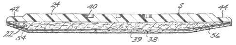
Fil;. 1 is a top plan view of the snip S before it has been cut to the proper
dimensions
to be wrapped about a golf club handle. In Fig. 2, the strip S is shown being
formed with
sidewardly and outlvardly extending recessed reinforcement side edges,
generally designated
12
CA 02243815 1998-07-23
PA TENT
Docket No. IVINN..J2193
42 and 44. Fig. 3 shows the appearance of the ship after such reinforcement
side edges 42
and 44 have been for~rred thereon. The reinforcement side edges 42 and 44 are
preferably
formed along the major porrtion of the sri-ip by means of a heated platen P
shown in Figs. 2
and 7. Refen-ing thereto, platen P may be of conventional metal construction
having a
horizontal base 45 formed at its opposite sides with depending legs 46 and 48.
The lower
ends of the legs are configured so as to form the recessed reinforcement side
edges 42 and
44. Thus, the lower portion of the platen legs are provided with like -
configured mirror
image cavities 49 and S0, having a horizontally extending surface, the inner
portions of
which extend upwardly and inwardly, while the outer edges thereof are curved
sidewardly
and downwardly. Tlre platen P is heated in a conventional fashion as by means
of electrical
resistance elements (not shown) and urged downwardly against the sides of the
strip S so as
to compress side portions of the polyurethane layer 2G below the normal upper
surface of
such polyurethane layer in the manner shown in rig. 7 to define the recessed
reinforcement
side edges 42 and 44. Such compression increases the density and strength of
the
polyurethane layer in the vicinity of the side edges 42 and 44. It has been
found that the
width of the recessed reinforcement side edges 42 and 44 may be approximately
2
millimeters, while the depth of the major portion thereof may approximate 0.5
millimeters.
13
CA 02243815 2003-08-05
..~ ~.,.'r,~sr~~
i '.! f t :: f ,.
~>~iX..'~c':6 i~it7, ~~!~~.%~i.~i~~~~J
-3-$1:'c.'T' ~~-3~: ~..~.':~~k,''Ls~3-C::~'.~%,~::l~t .S.~,'~,~
'c.'.;.e~~:'.:C -'~,''~,' f?.,''~s:~ ~~ .~7~ v~.'. :3f..'C':~~ ~L?~1~':~ 1-
~'i, ~..'.i~ .~'zvTk$. ;;~'dh~.'.. "-t.':'.'
r>.~ ~ ~ -r~ ~ t::, :'r ~ra.~; . ,>.5' .. ~f ~ 's(? :~ _. L' ; ~ ~"~
y..,,.,;.s:.> ~. ~~-~:x
"3<..~~ ;~v~s.~" Sl:. ~~:3 a .;.I~' ~::~,tt ~>:~~ ~.f.~.. .,~,.~a.~'.,;:
a#3.~'~J1;.~': w,.3c~. ~.'.."i1 ~~~I~,w "als~~ .s : <3.~'3~' ,.si ~
~csr.t,.a,t:: ,,: ~;~ .
I~: ~:e.i:~~:. ~ s~~~~ f~ i~~~;. ~~~~ ~~~~.~;.~ ~;;'x;-li~ lf~~'°w'
'~.::,~ ~~U~.~~ ~~~-~~ :'~~~~. :~F ?x:~.~ cs~;~~'~d~3' a;:~.~
~~~<~~~;~.~~~.' :~t~~.r~~rhx:~ ~~~3.~; ~s~s~~ ~~~ ~~~~ ~<~;.
.<°~.i~':.~~ ;~~~~~~ ~~~;~r~~fr. ~~;.~~ ~~f~~~, ~~~r~ #~=.3~~~>~~> tl~s-
~, ,x y .~ .n ~~~ ~ ...k .~w <a. ~- i.yC..y ~'.y -. <~ yrrr~ C,: .E: ' aS ':%
~ .~
afx~e.~a~~. ~::~ ~:~ ;~a~~>:~>,..s~ ~z. ~.:x~, ~-..~t.~r~; :.t~~,...ax~~..
fs~' i:~a~ ~:~Iv ~z~ ~.~, :~>~~..:.. ~.ki~~~Y~~~. ~.~t~.~,~.:o> ~e~~
-~'s A ~-, i o< ~, ,- , ' ; ;,s~"- , <> ~ ~:3. ,. .,.~ j.S .. ! .i s,.., ; c .
ifs a~,~~4 r,. .,z~ :~. °~:f~~.~,...~~.~.ickA;gin .~-~~~v~~:~:r ~-'>~-
~~.~. ~3~:;u.~ ;,.,. ~.; vE~,Y-f;: .. . ~'~~:.~a;;.~v..:.~,~ ~
::<~::~~~:c°.~: ~s.i~c. ~,.xu~. .: ~
';'~k#.~ ~~t;: >i~1~3-.S'x''~i;l' '~~',~i:i~ :",~.~'a'.~'l~ft:.i:e :':F.f~''a'
C>.~~~.~..~''. '_3~j" .~'..~, ~'~.t~SG SC~.<%f'' .".t'~ ?'~1f1~% ~3~; ~.'"..'f
::~''aTk",. ~:L'~il~~i,~'.~ :x~.CIL'.. ';-:~~~:.
.: . ._. s C: r ...
.~5~'f ~'e3;x':: ~~' .~'3~.':k-5~~"l..
~':,°~~'~°r'#.~~. .~'.'.t3'~ls% '#.i5 ?w:. ~ ~..'' ':~:x~,.'~ <
rm.'s. ~.r.~s9~'f'; J':: :->~3i.3'tfo-'s'#. ~R3'S~, i'f3""~.~3. ~3.s~' <:.
r','.' i'~;;wel'. Y3.~'s~i,'F'-.?~~~'.'w'
ry>~ . f~.. ::Sa...,,,.~ ~ .~.':' ''..,:-, ~,~ S>' ...'',7 Yir' ~,' ,:; -~ ='
~Y a. if:"' y ~ "' ~, -; ri.y >
~~:~v~.~...~~~~'~~~~., ~_.,~, w t.~ ~"..s.3~~~:;~. ~~r ~~._~~~A.~~, ~-~e
~~~.~~, ~.~~ 4w~s~z.. ~.~- ~x~w. ~,.~~. X31 ~~~,.. ~,.r..,..~,.a.~
y' v: 'i~k-;:.. y ~, ic> "~ .<j ': ; C'fr'~ -r>. y~ ..5' :-~~~:.~ S~'~L:~" fF.
r. F...:.y.m:.o y~j'~z s-y,~.'.
~~y4e~~.~.i~e,.. .e ..~.,... .~~..:~.c,..~'.~~:>~~.~H-. ~".ai;~''w' ~i ~. .
~~t~t....:..~,~C~~,..e.~ ~. a .:H ~~~~.,...~~,.e:'~ f: ~..:.4, ~'. v~.x.. ~..~
~.'..~.n4:i~' ~i'.i>~~.,~.;.,.
/...;5 ' ," - '}. .> >.:,.>$,7(>'~ Ys S '~ ,'.'' ':r:< ' "'> .'' ~>t>l;;:u j
.$>:: ' ''f.'f p. ~~' , ~~ ~ S.x ' 'as
~~~: ~.~~~.i~.~~:~ ,,~~,~s c~v3. '.( A~~: .~,,,.:. ~,c,~::a: ~.< ~.~...:
~.~~:,.:~:~.,:~;;Ei~~~ ;~~"w~w. ~... ,.. ~.c ~.~~~"3~. ,.~~.~:~r. a.~ ~s.~t.-
...
Y
~li'~~~~z ~'~~' " ~-s':' ' ,t~3F :t 'r;t3 i f'i t,' ' ~ c, v >;~;;~v s> ~:->
y' ;~
t'.~ C,~... ~i,.~.i3~L~' ~..~.. i:<;.~J .~. ~',~~% :.~,:~'s~::. ,_ '~'~.?s;~#,
.3_ ~.''w.~~ .; t.. .~e,~'~#'~i".. :"~~ ''~~ H~"tai; .#.. i v L.:
, ~: r:.' ; r, ~ v cr -' : C ..s ,, ,...,. < ('> ~ ~ z ~' f? y !! :.; 4,Y,~, '
., ..k , . _ ,
' f 7 X' s ~...''Yx.C3w~~: z: '".a'~.t..~~.~'~ ~fi
~.~,. .~;,~~.~ v ~~.<,.. ~..~~. f.3 ft.r ft.~~.C'~ i3C~.~~~5.~z~;; v.'~;,...
.... .'~~.~i r~~~',' ~. .~.c~'f e'"ir.,. , ~Y~ :.~.~s.~e .. .~.''i J f~~A~
'~x~iC~.C:6~I~'~L33~3. '-.~''3.."'.-Y.'~'t,'' ~..~"',f. 'f,~I~ n.u'~,C. 'n:3
w~~FEi~w'.''w::. :~ ;.::"~ . l~ 'E:''~'lI>.~n~ ~~~w.~. iL.~',~r~.. ',''.~.
3,i: °:3~'fi#'~~~.! t' S~''~."Cf..3., C';i'.
s. ,. ,.
G., -f . r
,.' >.~a'i7ø: i. ~ rf ~, r.i ,. , f',.: ,,~ z. ~~.~.' "jy n a
~ 'C7c.n-..~, ,-
:::r f'' ~'I " 5! . ;sw'' s:' ~'..~,. ~"~;-~i%~ t~,~ Qf ~ '~: :.~ . ..4..,..:.
s ~~:. .3~.~C''S'~.'~ ...
i;...3..'x~a,~.3~.'~;. axv,, .,. w~.;.~,.., ~.;.~.:..a . o.. x:i ~'ss,.l.-
.~.~.3 .. .3~ ~.~'1:: :i~4~ ~:.~ < H, .ai 1'~
~~v~~i$.~.r vr~ >:~~,~';:~:v ~~ ~.~~.e~?t v.~a~. At. s ~~~~~ar~:~s,~ ~~~~ir 5~
~~~ic~~. ~'~~~v~x~~r ~~~~a
CA 02243815 1998-07-23
l'A TENT
Docket No. WINN.42293
formed with longitudinally extending slit 66 that extends from the upper
portion of the sleeve
to the bottom of the sleeve to permit installation on golf club handle H.
Underlisting sleeve U of Figs. 12 and 13 is removably disposed upon a
conventional
collapsible mandrel M (Fig. 21) before strip S is spirally wrapped about the
sleeve to provide
a slip-on grip embodying the present invention. Underlisting sleeve U-2 is
adhered to golf
club shaft H before strip S is spirally wrapped about such sleeve in the
manner shown and
described in my U.S. Patent No. 5,584,482. To apply the strip S to either of
the underlisting
sleeves, the quick-release tape 39 is peeled off the adhesive 38 on the
underside of the felt
layer 22. The strip S is then spirally wound around the sleeve starting with
the upper end of
the sleeve. The tip 65 of the strip's starting end shown in Figs. 3 and 10 is
inserted in groove
64 of the sleeve and the strip is wrapped about 1 %2 times around the upper or
butt end of the
sleeve to provide a smooth configuration of the strip on the sleeve, as shown
in Figs. 18 and
19. The strip of Fig. 4 and Fig. 5 is spirally wrapped about a bare golf club
handle.
CA 02243815 1998-07-23
PATENT
Docket No. Ii~INN.42293
Referring now to Figs. I5, 1 G, and 17, there is shown a resilient spirally
cut sleeve or
underlisting member U-3 which abuts and is adhered to golf club shaft H, and
over which
is spirally wrapped a felt-polyurethane strip member S.
More parrticularly, resilient spirally cut sleeve U-3 may be of unitary
synthetic plastic
foam or robber conshnction. Such sleeve includes a cylindrical butt portion 70
from which
depends an integral main portion 72. Butt portion 70 is fomned with an
integral cap 74
which abuts the upper end of the golf club shaft. The inner diameter of the
cylindrical butt
portion 70 should be so selected as to affect a snug fit with the upper
portion of the golf club
shaft when telescopically applied thereto as shown in Fig. I5. The lower end
of main portion
72 is for7ned with a triangular tongue 76. A conventional adhesive carrier C
shown
particularly in Fig. 15 is utilized to attach sleeve U-3 to tire golf club
shaft H. Such adhesive
carrier C includes an elongated flexible plastic body 78 coated on its inner
surface with an
adhesive 80. Protective tape 82 initially cover the adhesive 80. The adhesive
carrier C
extends along the length of main portion 7?. To apply the spirally cut
underlisting U-3 to
I S the handle H of a golf club shaft, the cylindrical butt member- 70 is
slipped over the upper
end of the golf club shaft to telescopically interfit therewith. Thereafter,
as shown in Fig.
15, protective tape 82 is peeled off adhesive 80 and the main portion 72 is
spirally wrapped
16
CA 02243815 1998-07-23
PATENT
Docket No. Ii~INN.;11293
about the golf club shaft with the side edges thereof in tight abutment, until
the entire length
of the elongated base portion has been wuapped about the shaft, as shown in
Figs. 16 and 17.
Referring now to Figs. 18, 19, and 20, ship S is shown being spirally wrapped
about
the underlisting sleeve U. It is important to note the underside of the
recessed side edges 42
and 44 of the polyu-ethane layer 30, overlap one another, with such edges
being secured
together in a watertight manner by adhesive 38. The provision of the slanted
side edges 54
and 5G of felt layer 22 per-rnits such overlapping of the recessed side edges
42 and 44. The
use of slanted side edges 42 and 44 having different widths permits a more
pleasing
longitudinal profile of the completed grip while the nawower slanted side edge
54 reduces
the amount of felt cut off the felt layer thereby maintaining the shength of
the completed
strrp.
It should be understood that where the ship S is spirally wrapped around
underlisting
sleeve U while the sleeve is supported on collapsible mandrel M, as shown in
Figs. 12, 13,
and 21, and after the ship has been spirally wrapped around the sleeve, the
mandrel is
collapsed and the sleeve and ship assembly axially withdrawn therefrom. The
resulting
assembly defines a grip embodying the present invention which rnay be marketed
as a
replacement grip or as original equipment installed on a complete golf club
(the so-called
17
CA 02243815 1998-07-23
LATENT
Docket No. WINN.42293
slip-on grip in the golf industry). When the underlisting sleeve U is slipped
over the handle
of a golf club, the guide cylinder 62 rigidifies the comparatively flexible
lower end of the
sleeve U to facilitate slipping the sleeve onto the handle.
Referring to Figs. 22 - 25, strip S of Fig. 4 and 5 is shown as being spirally
wrapped
about a bare handle H of a golf club shaft. Handle H may be radially expanded
at a greater
angle than the main portion of the golf club shaft to enhance the grasp of a
golfer. This
design is commonly termed a "big butt" shaft in the golf club trade.
In Fig. 23, strip S is being shown spirally wrapped about golf club handle H.
I-Iandle
H is of hollow construction. Fig. 24 shows the upper end of handle H provided
with a
conventional solid cap 98 that is telescopically received by the upper end of
handle H. Fig.
25 shows the handle H provided with a cap 99.
Referring now to Figs. 29 - 32, there is shown a modified form of strip SM
embodying the present invention wherein the underside of the felt layer 22' is
further skived
to form an upwardly extending groove 100 along its length. Other than the
addition of such
18
CA 02243815 1998-07-23
PATENT
Docket No. ~i'INN.:lZ293
groove, the construction of ship SM is similar to that of strip S and the
elements thereof bear
primed reference numerals.
As shown in Figs. 31, 32, and 33, when ship SM is spirally wrapped about an
underlisting sleeve U, the bare handle of a golf club or the handle of a
tennis racquet, the
groove 100 will form a spirally extending concave depression 102 along the
length of the
grip. Such depression 102 cooperates with the two generally convex spirally
extending
convex profiles 103 created by the overlapped slanted side edges of the
polyurethane layer
2G' to increase the surface area of the grip engaged by the user's hands to
thereby enhance
the frictional contact and hence control of a golf club or tennis racquet by a
user.
Additionally, a distinctive appearance of the grip is obtained. Furthermore,
the frictional
contact of the overlapping joints of the strip SM between adjoining golf clubs
in a golf bag
is reduced when a bolf club is removed from the bolf bag to fiu-tlrer resh~ain
unraveling of the
ship from the golf club handle.
In Fig. 33, the ship SMl is shown spirally wrapped about the handle H of a
tennis
racquet.
19
CA 02243815 1998-07-23
PATENT
Docket No. WINN.dZZ93
It should be particularly noted that the gn7p of the present invention is
lighter in weight
than conventional grips. Accordingly, more weight is distributed to the club
head thereby
increasing club head speed without increasing the weight of the golf clubs.
Such weight
savings moves the center of gravity of the golf club closer to the clubhead,
increases the
club's moment of inertia, and reduces the overall weight of the club and
thereby permits a
higher clubhead speed for greater distance. Less shaft twist is also achieved.
Applicant's
unique lightlveight cap 99 shown in Fig. 25 conhibutes to the light weight of
applicant's grip
while positively restraining unraveling of the strip relative to the club
shaft.
It will be apparent to those skilled in the ar-t, that various modifications
can be made
without departing from the spirit and scope of the present invention.
Accordingly, it is not
intended that the invention be limited except by the appended claims.