Note: Descriptions are shown in the official language in which they were submitted.
CA 02243839 1998-07-17
1
Specification:
The invention relates to a method and device for handling
material webs coated with adhesive on one side, especially for
applying sections of of an adhesive tape to folded cardboard
boxes, the material web or the adhesive tape being drawn from a
s first reel and, once this has been used up, a new material
web/a new adhesive tape beign connected to the material web
which is running out.
Material webs, coated on one side iwth adtive adhesive', or
io adhesive tapes are used, for example, to close folded cardboard
boxes. A so-called tape assembly applies the adhesive tape, for
example, on the upper side and ont he lower side in the region
of abutting closing flaps on the folded cardboard box. The
adhesive tape consists of a plastic web with active adhesive
is applied to one side of it.
The material web or the adhesive tape is made available as a
(coiled) reel. When it has been used up, a new material web or
a new adhesive tape has to be connected to the one which is
2o running out, with as little outlay as possible.
FOC547D.DOC
CA 02243839 1998-07-17
2
Accordingly, the object underlying the invention is to propose
a method and a devi ce whi ch are sui tabl a for ensuri ng si mpl e,
reliable handling of adhesive tapes, especially in joining a
new adhesive tape to one which is running out.
In fulfillment of this object, the method according to the
invention is characterized in that the new adhesive tape or the
new web with a free initial section to connect it to the
io outgoing web is pressed with its adhesive side ,against the
facing, adhesive side of the outgoing web.
The initial section of the new web is held in readiness by a
holding device which may be actuated - by machine or by hand -
is against which the initial section of the adhesive side lies.
The contact region of the holding device is so configured that
the retaining force for the initial section is sufficient of
fix same until it is in contact with the outgoing web. Through
contact with the adhesive side of the outboing web, greater
2o retaining force is generated which fixes the initial section to
the outgoi ng web as a resul t of g1 ui ng, such that the hol di ng
device can be detached from the initial section of the new web.
The holding device for the initial section of the new web is a
25 movable, especially swivelling, arm which, through a transverse
movement, presses the initial section against the outgoing web
in the region of a deflection of same, especially in the region
of a reflection roller.
3o A further special characteristic of the invention consists in
the fact that the active reel, from which the material web is
drawn , is run until it is completely used up. thus no
remaining section of the material web is left on the reel or on
to reel core. In the invention, special measures are provided
35 whi ch ensure that, even after the end secti on of the materi al
web has been drawn from the reel or the reel core, a certain
tension is preserved in the material web, such that said web
can be transported without faults, the formation of creases or
the 1 i ke, unti 1 a new materi al web i s connected. To thi s end,
4o according of the invention a cross-sectional deformationof the
material web which is running out is provided.
FOC517D.DOC
CA 02243839 1998-07-17
3
In the region of a splicing station, there are disposed on a
common swivellable carrier, especially on a carrying disc, two
reels of tthe adhesive tape, namely a supply reel and a
replacement reel from which the new web is drawn. Through the
rotation of the carrying disc, the supply reel is respectively
moved into a predetermined run-out position and the replacement
reel into a waiting position. The initial section of the new
web is preferably drawn manually from the replacement reel and
to laid on the holding device.
Further details of the invention relate to the design of the
splicing station and to members for transferring adhesive tape
to objects.
20
An exemplary embodiment of the devivce according to the
invention is explained in greater detail below with respect to
its construction and the process run, with the aid of the
drawings. These show:
Fig. 1 a device for applying adhesive tape to folded
cardboard boxes, in simplified side view,
Fig. 2 a splicing station as a detail of the device
2s according to Fig. 1, on an enlarged scale,
Fig. 3 the splicing station according to Fig. 2, in
transverse view,
3o Fig. 4 a detail fo the splicing station , on an enlarged
scale,
Fig. 5 a transverse view of the splicing station in a plane
offset to Fig. 3,
Fig. 6 a retaining shoe of the splicing station in an
enlarged cross-section, in the cutting plane VI-VI
of Fig. 5.
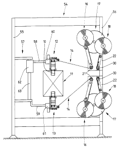
~o The device shown in Fig. 1 is concerned with the application of
an adhesive tape 10 to a folded cardboard box 11. Applied
FOC547D. DOC
CA 02243839 1998-07-17
-4
s
respectively to an upper side and a lower side of the folded
cardboard box 11 is an adhesive tape 10 arunning in the
longitudinal direction of same, in order to connect folding
tabs to one another.
For applying the adhesive tape 10 there are respectively an
upper and a lower tape assembly 12, 13 which automatically
apply an adhesive tape 10 to the folded cardboard box 11.
io The adhexive tape 10 is separated from a continuous strip or a
continuous material web 14. The latter consists preferably of
p1 asti c and i s coated on one si de wi th an acti ve adhesi ve 15.
The materi al web 14 i s drawn from the reel 16 and 1 ed to the
tape assembly 12, 13. The reel 16 is located in the splicing
15 station 17 together with a replacement reel 18. On the present
embodiment, the device is equipped with two matching splicing
stations 17, in order to supply each tape assembly 12, 13 with
material automatically.
2o Once the active reel 16 has been used up, the replacement reel
18 is connected largely automatically to the outgoing material
web 14 in the region of the splicing station 17. On the present
example, however, certain manual intervention is proficed for
changing the reels.
The replacement reel 18 is prepared for the exchange while the
material web 14 is being drawn from the (active) reel. To this
end, an initial section 19 is drawn (manually) from the
replacement reel 18 and held in readiness adjacent of the
3o material web 14. When the material web 14 has been drawn either
partially or completely from the reel 16, the initial section
19 of the replacement reel 18 is pressed against an end section
20 of the material web 14 which is running out, and thus the
material web 14 is connected to the replacement reel 18.
In order to carry out the exchange of webs, the splicing
station 17 is provided with members which work automatically.
The (continuous) material web 14 is led, at the exit of the
splicing station 17, over a deflection member, namely over a
4o deflection roller 21. The material web 14 is coiled on the reel
16 in such a way that the adhesive 15 applied to one side of
FOC547D.DOC
CA 02243839 1998-07-17
the material web faces outwards in the region of the deflection
roller 21.
The deflection roller 21 is mounted at a spacing from the reel
5 16, on an (upright) carrying wall 22. The material web 14
isdrawn from the reel 16 is led over a leading or guiding
member of the deflection roller 21, namely over a shoe 23. The
latter is configured as an elongated one-armed lever with a
(lower) pivot bearing 24 adjacent to the deflection roller 21
1o and above same.
The shoe 23 is provided with a guide surface 25 for the
material web 14. The shoe 23 - seen in cross-section - is
configured as an elongated hollow body with a corresponding
cross-sectional contour of the guide surface 25. As can be seen
in particular from Fig. 6, the shoe 23 is configured
approximately C-shaped in cross-section, i.e. as a profile open
at one side. The guide surface 25 forms sloping side strips 26,
27 at the edges. The latter pass into guide limbs 28, 29,
offset again by 90°, at their free outer edges.
The material wewb 14 runs constantly past the guide surface 25
contoured in the manner described and thus receives a
corresponding, shaped cross-sectional form. By this means, the
material web 14 is prevented from being deformed in its
longitudinal direction, in particular from becoming creased. In
addition, because of the design of the guide surface 25, the
shoe 23 exercises a retaining force on the transported material
web 14. It is thus possible with this device to run the
3o respective reel 16 until it is completely empty, i.e. without
separating off a remaining portionof the material web 14 which
stays on the reel 16. Thi s feature and the desi gn of the shoe
23 are special characteristics of the device.
In order to change the reels, the shoe 23 is moved, by being
swivelled out of the movement plane of the material web 14,
into a position which is shown in a dot-dash line in Fig. 2.
When the shoe 23 is brought back agin into the position in
which the material web 14 is adjacent to the guide surface 25.
ao
FOC5470.DOC
CA 02243839 1998-07-17
G
The replacement reel 18 or its initial section 19 is held
adjacent to the deft ecti on rol 1 er 21 ready to be connected to
the material web 14. The initial section 19 is adjacent to a
transfer member, namely a transfer roller 30, which is mounted
s for i is part on the 1 ower or free end of a one-armed transfer
lever 31. The latter may be swivelled in the region of a pivot
bearing 32. disposed adjacent to the replacement reel 18. This
pivot bearing is also disposed on the common carrying wall 22.
The relative position is chosen to be such that, with a swivel
to movement as per arrow 33, the transfer rol 1 er 30 i s swi vel 1 ed
out of its initial position as per Fig. 2 into the transfer
posi ti on as per Fi g. 4. In the 1 atter, the transfer rol 1 er 30
is directly adjacent to the perimeter of the deflection roller
21, and in such a way that a free end of the initial section 19
1s is pressed against the material web 14 in the region of the
deflection roller 21.
The replacement reel 18 is positioned in such a way that the
initial section 19 with the adhesive 15 faces the transfer
2o roller 30 or the transfer lever 31. Accordingly, the initial
section 19 lies with an adhesive surface against the perimeter
of the transfer roller 30 and - on the present embodiment -
against the transfer lever 31.
2s Transfer roller 30 and/or transfer lever 31 are so designed
that, on the one hand the material web with its adjacent
adhesive side is held sufficiently, but on the other hand, when
pressed on a side of the material web which is provided with
adhesive 15, said web grasps the end of the initial section 19
3o and draws it from the transfer roller 30 or transfer lever. 31.
For this purpose, the transfer roller 30 is provided along its
perimeter with projections or raised parts. In the present
case, these are projecting points 34 which are here formed by
pyramid-shaped raised parts 35. The raised parts 35, and thus
3s the points 34 of same, are in the present case disposed in
longitudinal and transverse rows, evenly distributed along the
perimeter of the transfer roller 30.
A holding piece 36 for the material web 14 or the initial
4o section 19 is formed in the region of the transfer lever 31,
adjacent to the tranfer roller 30. The initial section 19 is is
FOC547D.DOC
CA 02243839 1998-07-17
7
likewise adjacent to said holding piece. The holding piece 36
is provided with raised parts 35 and points 34 in the same way
as the transfer roller 30.
When the new material web or the initial section 19 is
transferred to the material web 14 which is running out, a end
region of the initial section 19 is pressed with its non-
adhesive side to the adhesive side of the material web 14, and
thus a sufficiently durable connection is made. The material
1o web 14 i s thereafter drawn from the repl acement reel 18 whi ch
assumes the function of the active reel 16.
Connecting the initial section 19 of the new material web to
the material web 14 which is running out is performed
automatically. The outgoing reel 16 is run until it is
completely empty. The end of the material web 14 is scanned
Provided on the present exemplary embodiment (Fig. 2) is a
photocell 37 which observes the material web 14 which is
running out. Instead of this, a circulating, contactless
2o calliper, for example, an initiator can be configured in the
region of a rotating bearing of the reel 16. After the material
web 14 has run out, this calliper detects the lack of movement
in the reel mounting or the reduced rotating speed as a signal
for the complete run-off of the material web 14.
2s
When the complete run-off of the material web 14 has been
determined, the transfer process is initiated immediately. To
this end the transfer lever 31 is swivelled in the described
direction until it is in contact with the perimeter of the
3o deflection roller 21. The swivel movement of the transfer
roller 31 is effected by a control unit actuated by the
photocell 37, namely by an (electro) cylinder 38, the piston
rod 39 of which is connected to a transversely oriented arm 40
of the transfer lever 31.
On the present embodiment, the replacement reel 18 is prepared
manually for being connected. The initial section 19 is drawn
by hand from the replacement reel 18 and brought into the
described position in contact with the transfer roller 30 and
4o transfer 1 ever 31. A stati ovary b1 ade 41 i s 1 ocated bel ow the
transfer roller 30. An end of the initial section 19 is
FOC547D.DOC
CA 02243839 1998-07-17
8
separated on this blade, such that the initial section is in
contact with the transfer roller 30 always in an exact relative
position. Moreover an exact end edge is created by the balde
41. The blade 41 is likewise attached to the carrying wall 22.
The device or the splicing station 17 is provided with
monitoring members which monitor the presence of material,
namely the material web 14, in the important regions. The
embodied idea consists in the fact that, on the one hand the
io rotary movement of the deflection roller 21 presupposes the
presence of the material web 14. On the other hand, however,
the orderly drawing-off of the adhesive tape 10 can be
monitored, namely in respect of its length. To this end, the
rotary movement of the deflection roller 21 is monitored by
contactless callipers, namely by a so-called initiator 64. The
latter cooperates in a non-contact manner with a control member
rotating with the deflection roller 21. In the present case, a
control disc 65 is provided with (threee) radial projections
66 disposed at equal peripheral spacings from one other, and is
2o arranged on a shaft for the deflection roller 21, i.e.
rotataing with same. The initiator 64 is acted upon by the
projections 66 of the rotating control disc 65. By this means,
on the one hand the rotary movement of the deflection roller is
basically recognized, but on the other hand so is the length of
2s the drawn-off section of the material web 14.
Active reel 16 and replacement reel 18 have a predetermined
relative position as a result of the operating manner of the
splicing station 17. To this end, the reels 16, 18 are mounted
3o so as to be adjustable, namely on a member which may. be
swivelled or rotated. In the present case, this is an (upright)
carrying disc 42. The latter is rotably mounted with a central
bearing 43 on the carrying wall 22. The carrying disc 42 is
rotated after each reel change, in such a way that the
35 replacement reel 18 moves into the position of the active reel
16. The carrying disc 42 is here rotated clockwise as per arrow
44. The material web 14 here moves out of the region of the
repl acement reel 18 unti 1 i t i s i n contact wi th the shoe 213,
the cross-section of the material web 14 being deformed as it
4o enters the cavity of the shoe 23. On the present embodiment,
the shoe 23 may be swivelled around the (lower) pivot bearing
FOC547D.DOC
CA 02243839 1998-07-17
9
24 i nto the posi ti on shown wi th a dot-dash 1 i ne i n Fi g. 2 . I n
this position, the rotation of the carryin disc 42 is carried
out. The shoe 23 is then swivelled byck into its working
position and, in so doing, picks up the material web 14.
On this embodiment, the carrying disc 42 may be rotated by
hand. Handles are provided for this purpose, one handle 45, 46
i n the regi on of each reel beari ng 47, 48. The handl es 45, 46
projecting transversely can be grasped and thus the carryin
1o disc 42 is turned.
The operating position of the carrying disc 42 is fixed by a
shap-in pin which may likewise be actuated by a grip 49 and
whi ch enters a shap-i n bore 50 of the carryi ng di sc 42 to f i x
is same to a holding device, namely to the carrying wall 22.
The handles 45, 46 in the region of the reel bearings 47, 48
have a dual function. Throught springs 51, the handles exercise
an axi al 1y di rected pressure on the reel s 16, 17 or on a reel
2o core 52. By this means, a braking effect is generated as a
result of friction in the region of the reels 16, 18. The
braking effect may be set with the aid of knurling wheels 53
which can be adjusted to alter the tension of the springs 51.
25 A further special characteristic relates to the arrangement of
the tape assemblies 12, 13. The device is attached overall to a
portal-like carrying frame 54. The two splicing stations 17,
arranged the one above the other, or the carrying wall 22 of
same, are/is attached to an upright support 55 of the carrying
3o frame 54. The two tape assemblies 12, 13 are mounted an a
holding device 57 on an opposite support 56. The holding device
has an upper and a lower carrying arm 58, 59, projecting
transversely. One tapae assembly 12, 13 i s mounted on the end
of each carrying arm. Each tape assembly 12, 13 may be
35 displaced with a guide 60, 61 on the carrying arm 58, 59, such
that each tape assembly 12, 13 an be positioned exactly in a
horizontal direction.
In addi ti on to thi s, one of the tape assembl i es 12, 13 i n the
4o present case the upper tape assembly 12, may be adjusted in a
veertical direction to adapt to different formats of folded
Focsa~o.ooc
~ CA 02243839 1998-07-17
cardboard boxes 11. The carrying arm 58 is connected to a
vertical guide 62. The latter may be displaced in a vertical
direction on an upright carrying rod 63. Said rod is part of
the holding device 57.
s
FOC547D.DOC