Note: Descriptions are shown in the official language in which they were submitted.
CA 02243961 1998-07-21
W O 97/26829 PCTAL97/00030
SURGICAL IMPLEMENT PARTICULARlY USEF~ FOR IMPLANTING
PROSTHETIC HEART VALVES
RELATED PATENT APPLICATION
The present application is a continuation-in-part of U.S Patent Application Serial
No. 08/640,149 filed April 30, 1996.
FIELD AND BACKGROUND OF TH~ INVENTION
The present invention relates to a surgical implement particularly useful for
implanting a prosthetic device in an excised ~nn~ s The invention is especially useful
for implanting a prosthetic heart valve, and is the, ~r" e described below with respect to
such an application. The invention also relates to a novel valve holder particularly
useful with the above surgical implçm~nt The invention also relates to a surgical
method for implanting prosthetic devices, particularly heart valves.
The surgical leplAc~ ont of a defective heart valve has become a widely practiced
surgical operation. In such a surgical operation, the defecting valve is surgically
removed, and a bio or met~.h~nical prosthetic valve is implanted in the excised annulus by
a plurality of sutures, usually varying from 12-20, depending upon the size of the
excised ~nmlllls Such a surgical operation involves cardiopulmonary bypass circulation
and cardiac arrest. The longer the period of cardiac arrest, the greater the danger of
post-operative complications. Many implements have been proposed for use in such a
surgical operation in order to shorten the period of cardiac arrest. Exarnples of the
known devices are described in US Patents 4,185,636, 4,492,2''9, 4,932,965, and in my
prior US Patent 4,702,''50. However, insofar as I am aware, none of these previously
known devices has found widespread use
CA 02243961 1998-07-21
W O 97/26829 PCT/~L97/00030
OBJECTS AND BR~EF SUMMAR~ OF T~IE INVENTION
An object of the present invention is to provide a novel surgical implement
particularly useful for impl~nting a prosthetic device, especially a prosthetic heart valve,
having advantages over the previously known impiçm~nt~ incl-l-ling that of my prior
Patent 4,702,250, as will be des~;.ibcd more particularly below. Another object of the
invention is to provide a valve holder of a novel construction particularly, but not
exclusively, useful with the above novel surgical i..~ P~ Another object of the
invention is to provide a novel surgical method for implanting prosthetic devices
especially valves.
According to one aspect of the present invention, there is provided a surgical
mplement particularly useful for ;...p!~..l;l-g a prosthetic device in an excised annulus by
means of a plurality of sutures, Co-l-p.i~..-g. a manually grippable handle; and a suture
retainer carried by the handle; the suture retainer including an outer annular face divided
by visually discernible dividers into a plurality of divisions, one for each of the sutures to
be applied, to facilitate the appiication and uniform spacing of the sutures.
Acco.-lh~g to further realu.es in the described plt;re .~;d embodimP-ntc~ each
division inr1~ldes at least two slits for receiving and releasably letai~ g the opposite
ends of the respective suture to f~r.iiit~te identifying and tying the opposite ends.
Pltrel~bly, each division inrlllcles at least four slits to allow the application of at least
one additional suture at the respective division and at the option of the surgeon, as well
as to f~rilit~te the application of the sutures without precisely aiming them within the
,c~ e division when applying the sutures to the suture retainer. Each of the slits
preferably has opposed, converging, yielding surfaces for receiving and releasably
retaining sutures of ~linele.lt thirL l~PCSFs
Accor.lin~ to still further features in the described ,~ r~ t;d embodiment, the
annular array of slits is defined by a coiled spring supported in an annular configuration
around the outer annu}ar face of the suture retainer for receiving and releasably retaining
sutures bet~,veen selected coils of the spring, the coiled spring inclu~1ing a plurality of
coils in each of the divisions. While such a construction is particularly advantageous,
other constructions, such as plastic discs having a slitted outer annular surface, or plastic
rods supported in an annular shape and having a slitted outer surface, could also be
CA 02243961 1998-07-21
W097/26829 PCT~L97/00030
used.
Accordi~lg to yet a further feature in the described plert:"~d embo.1imçnt~ the
outer face of the suture retainer in~ des a visually discernible representation of the
general shape of the excised ~nm-lus This f~rilit~f~s optimum spacing of the sutures
with respect to the excised ~nm~ The p,e~"c:d way of accomrli~hing this is to
make the outer annular face of the suture retainer of generally the same shape as that of
the excised ~nm~ s; preferably, however, it is of larger size to f~rilit~te h~n~lling the
sutures, but may also be of smaller size to ~ ? obstructing the surgical site.
According to a still further aspect of the invention, there is provided a surgical
imrlem~nt particularly useful for impl~nting a prosthetic device in a working area,
ColllyliS;Ilg. a manually grippable handle; a holder carried by the handle for holding a
prosthetic device; and an illl..";.~ or carried by the handle for projecting artificial light
into the working area.
The invention is particularly useful, and is therefore described below with respect
to, an im~ nPnt wherein the prosthetic device is a prosthetic valve having a valve
member pivotal to an open position or to a closed position, and wherein the holder is a
valve holder which releasably holds the prosthetic valve with its valve member pivoted
in the open position to permit light from the light con(luctor to pass through the valve
holder and the prosthetic valve held thereby and to i~ min~te the working area.
Acco. .Ih.g to a still further aspect of the invention, there is provided a valve holder
for holding a prosthetic valve having a sewing ring for impl~nting the valve in a
WOlking area, and a pivotal valve ~ be~ pivotal to open and closed positions; the
valve holder in~ in~ an ~tt~hinp section for ~tt~hing the valve holder to a
",~";~ Ahle surgical implement, and a releasable holding section for l~leasably holding
the prosthetic valve; the valve holder being formed with a bore e~fPn~ing through the
s-tt~c hing section and dimensioned to receive a light conductor from the surgical
implement and to space the tip of the light con(~-lctor from the pivotal valve member; the
releasable holding device holding the prosthetic valve with the valve member in its open
r position to permit light from the light conductor to pass through the valve holder and
the prosthetic valve held thereby to illllmin~te the w~lkillg area.
Several embodiments oFthe invention are described with respect to difrelell~ types
!
,
CA 02243961 1998-07-21
W O 97/26829 PCT~L97/00030
of prosthetic valves now co~ el~iially available with their I e~l,e-,live valve holders.
CA 02243961 1998-07-21
W O 97/26829 PCT~L97/00030
BRIEF DESC~IPTION OF THE DRAWINGS
The invention is herein described, by way of e~cample only, with reference to the
acco~ ,~,ying drawings, wherein:
Fig. 1 is a three--limen~innal view illustrating of one form of surgical implement
constructed in accordance with the present invention;
Fig. 2 is a top plan view illustrating the suture ~elail~,. in the implement of Fig. 1;
Fig. 3 is a top plan view of another type of suture ~ er that may be in~ ed in
the surgical implement of Fig. l;
Fig. 4 is a par~ial sectional view illustrating a modi~cation in the construction of
the suture I~Lalllel of either Figs. 1 or 2;
Fig. S illustrates another embodiment of the invention inrhl~insJ an artificial
ill~-min~tor;
Fig. 6 illustrates a still further embodiment of the invention illustrating another
type of ill- Imin~tor which may be used;
Fig. 7 illustrates another implement similar to that of Fig. 6 inelllt1ing a valve
holder for one known type of prosthetic valve;
Fig. 8 is a three-dimensional view of the valve holder of Fig. 7;
Fig. 9 is a three-dimensional view of the valve holder of Fig. 8 but as seen ~omthe bottom of the valve holder,
Figs. 10 and 11 are e~cploded side and top views, respectively, illuaLlafillg two
parts of the valve holder of Figs. 8 and 9;
Fig. 12 illustrates an implement similar to that of Fig. 7 but without a suture
retainer;
Fig. 13 is an exploded view illuaLldLill~ an illl~ lL sirnilar to that of Fig. 1'~ but
with a valve holder for another kno~,vn type of prosthetic valve;
Fig. 14 is a side view of the implement of Fig. 13 in assembled condition;
Fig. 15 is an e~ploded view illustrating another implement constructed in
accordance with the present invention inc~ in~ a valve holder for another type of
knov~n prosthetic valve:
Fig 16 illustrates onlv the valve holder of Fi~. 15 viewed from a different side;
I;ig. 17 is ~ side view of the vaive holder of Fig. 16 in partial section and also
SUBSTITUTE SHEET (RULE 26~
CA 02243961 l99X-07-21
W O 97/i6829 PCTnL97/00030
illustrating the manner of its ~ rhmPnt tO the implement; and
Fig. 18 is an exploded view illustrating the invention embodied in another
cQmmPrcially-available valve holder for holding a ~o ~ ,ially-available prosthe~ic
valve.
SUF2STITUTE SHEET (RULE 26)
CA 02243961 1998-07-21
W O 97/26829 PCT~L97/00030
DESCRIPTION OF PREFERRED EMBODIMENTS
The surgical implements illustrated in the drawings are for implanting a prosthetic
aortic or pulmonic valve, which involves making an excised annulus of generally curved
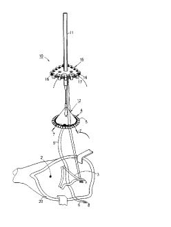
'' triangular shape Thus, Fig 1 pictorially illustrates at 2 the site of the ~ ced valve to
be replaced, at 3 the excised armulus of curved tri~n~ configuration prepared by the
surgeon after removing the defective valve and pl~pdl;ng the site for implanting the
prosthetic valve, and at 4 the prosthetic valve to be im~ nt-~ in the excised site 3. Such
a valve is normally provided with a se~,ving ring 5 for receiving the sutures 6 used in
implanting the prosthetic valve in the excised annulus 3.
As ~,vill be described more particuiarly beiow, each suture 6 is a double-arrnedsuture; that is, it carries a need~e 7 at each of its two opposite ends for passing through
tissue at the excised annulus 3 and through the sewing ring 5 of the prosthetic valve 4.
Each suture is also provided with a pledget 8, e.g., of "Teflon" (Reg.T M.), in order to
increase the surface contact bet~,veen the suture and the tissue receiving it at the excised
~nn~llllc
The surgical implement illustrated in Fig 1 is ~senerally de~iFn~ted 10 It inrlud~
a manually grippable handle ll and a valve holder 1~ for re~easably holding the
prosthetic valve 4 Any known type of valve holder may be used for this purpose, for
e~carnple as described in my prior US Patent ~,702, '50 However, when the implement
is to be used with illllmin~rion as described below, the valve holder is preferably one of
the constructions described below for the respective type of prosthetic vaive now
co~ ,..,;ally available
The surgical implement in Fig. I further includes a suture retainer, generally
desiPn~ted 15, carried by the handle 11 plefe.ably at the distal part of the handle close
to the prosthetic valve A coiled spring 16 is supported around the outer annular face of
the suture retainer 15, for receiving and releasably ~ ;..g the sutures 16 between
selected coils of the spring For this purpose, suture retainer 12 is integrallv formed
with a pluralitv of spaced ribs 17 having openings 18 ~Fig 2) for receiving the coiled
spring 16
r The coiled spring 16, as shown in Fig. 2, is made of wire of circular cross-section
coiied i~nto a heiiY and supported in an annular con~iguration around the outer annular
Slu~~ TE SHEFT (RULE 26)
CA 02243961 1998-07-21
W O 97/26829 PCT~L97/00030
face of the suture retainer I S. The coiled spring is applied under light traction so that
when supported in the illustrated cwed configuration, the coils are lightly pressed
together in the inner face 1 6a of the spring, and tend to spread apart slightly in the outer
face 16b. The coiled spring thus forms an annular array of slits having opposed,yielding surfaces for receiving and releasably ret~in-ng the sutures. The circular cross-
section of the wire used for making the coiled spring results in the outer surfaces
~Pfining the slits diverging in the outward direction, thereby f~cilit~in~ the insertion of
the sutures between the coils.
As described earlier, the outer shape of suture retainer l S is generally the sarne as
the excised annulus 3 ~Ic~a~t;d by the surgeon for implantin~ the prosthetic valve 4. In
the exarnple illustrated in Figs. 1 and 2, the defective valve to be replaced is an aortic
valve, which involves excising an annulus 3 of ~enerally curved triangular
configuration. Therefore the configuration of the surgical suture retainer 15 is also of
generally the sa ne curved triangular shape as the e~ccised annu}us 3.
The ribs 17, besides holding the coiled spring 16 in an annular configuration on the
outer face of the suture retainer 15, also serve as visually discernibie dividers dividing
the outer annular face of the suture retainer into a plurality of divisions, one for e~ch of
the sutures to be applied. For example, in the prosthetic valve illustrated in Fig. 1,
normaily fifteen sutures would be used, and therefore there would be f~een ribs 17
dividing the outer surface of the suture retainer into fifteen divisions, one for receiving
each of the fif'~een sutures. Each of the fifteen divisions defined by the ribs 17
a~commodates at least two (~ .ably three~ coils of the coiled sprine 16, dçfining at
least two suture-receiving slits, to f~riltt~te receiving, identif~ing, and tying the two
opposite ends of the suture to be received in the respective division. Preferably,
however, there are more than three coils, e.g., four or five coils, in each division. This
f~cilit~ s the appiic~tion of the sutures by the surgeon without requirin~ the surgeon to
aim the suture in a precise location in the l~,~yc.,Li~e division ofthe suture holder. It aiso
gives the surgeon the option of adding an additional suture or two at anv location of the
e~ccised annulus should this appear to be ne~~cc~tv or desirable during rhe course of the
surgicai operation.
~ ile the suture retainer I ~ is of generally the same e~cternal shape as the excised
Sl,~ 111 tJTE SHEET (RULE 26)
-
CA 02243961 1998-07-21
W 097t26829 PCT~L97tO0030
annulus 3, it is may be of larger size to facilitate h~nrllinsg and proper pl~c~ment of the
sutures in their respective locations. The suture retainer 15 may also be of smaller size,
and/or may be of Lldn~ale.~ plastic, to ~ illli7e obstruction with the surgical site.
The surtJical implement illustrated in Figs. I and 2 may be used in the following
manner for replacing a defecting aortic valve.
The chest is opened by a midsternotomy, and a cardiopulmunary bypass is
established by c~nnUl~tion of the aortic root and the right atrium. The aorta is then
cross- ciarnped, and cardioplegia is injected in order to arrest the heart. The aortic root
is opened via an S-shaped incision, the defective aortic vaive is excised, and an excised
annulus 3 of generally curved tr;~n~-l~r corLfiguration is ~e~ d for receiving the
prosthetic valve 4
- The surgical implement 10 is preloaded with the prosthetic valve 4 but not with
the sutures 6 to be used in the implanting Rather, the impiem~nt is e~uipped with a
suture retainer 15 of ap~,o,~,liate configuration (in this, of case curved triangular
configuration) corresponding to the excised annulus 3 to receive the prosthetic valve.
Each of the sutures 6 carries a needle 7 at each of its two opposite ends, and a pledget
8 at the location, or slidable to the location, of contact of the suture with the tissue
around the excised ~nnt~ c
The stitching is started by passing the needle 7 at one end of the first suture 6
through the non-coronary cusp rim 70 and then through the sewing ring ~ of the
prosthetic valve 4. That end of the sueure is then inserted betwesn a pair of coils of ehe
spring 16 at the division allocated to that suture bet~,veen the ribs 17 The suture is
slightly tensioned, and is releasably retained under this tension by the coils of the spring
The needle is then cut away from the respective end of ehe suture leaving an excess of
the suture at thae end.
The opposite end of the same suture is then applied in the sarne manner and is
inserted between a pair of coils ~ljac~nt to the one receiving the first-mentioned end in
the same division defined by the ribs 17 The needle at that end is also cut away leaving
an excess of the suture at that end
The coils of spring 16 releasably retain both ends of the suture such thal handle I I
may be~pulled slightlv outwardly to apply a tension to the two suture ends and also to
SUtfS ~ )TE SHEET (RULE 26)
CA 02243961 1998-07-21
W O 97/26829 PCT~L97/00030
pull out slightly the tissue engaged by the suture. The pledget 8 of the respective suture
provides a iarge surface are of contact between the suture and the tissue, thereby
perrnitting this tension while decreasing the possibility of tearing the tissue. If excess
tension is applied to the sutures, this excess tension will be taken-up by the sliding of
the sutures between the coils of the spring, thereby .~ g the risk of tearing the
annulus tissue.
The other sutures 6 are then applied in the same manner, one after the other,
according to the ~ LIlc:SS techniques, i.e., ~om the outside to the inside. They are
received b~ a~ rpnt coils of the spring 16 in their r~s~c.,Live divisions defined by
the ribs 17 of the suture retainer 15, acco~dil~g to their ~ e~ e locations in the
excised ~nn~ s
A~er all the sutures have thus been applied and their needles cut-away, handle 11
may then be moved slightly outwardly ~o tension all the sutures and to better expose the
e.Ycised annulus. If any suture is found to be insufficiently tensioned, this can be easily
corrected by merely pulling on the l~ c~,Li~/e suture to apply the proper tension to it.
As mentioned earlier, if excessive tension is applied to one or more of the sumres, the
respective suture will merely slip between the coils of the spring, thereby reducing the
risk of tearing the annulus tissue.
After the sutures have thus been applied to the excised annulus and tensioned tobetter e~spose the ~nn~ the prosthetic valve 4 is released from holder 1~ in themanner described below, and is slid into place into the ~nn~ Each pair of sutures are
then tied down and cut. The aortic opening is then sutured, and the aortic clamp is
released to allow the heart to resume beating.
The use of the surgical implement illustrated in Figs. 1 and 2 thus enables a
number of important advantages to be gained, as compared to the existing te~hn;qntoc
Thus, the novel implement enables the surgeon to select the type of suture to be used,
50rnethinsg not permitted by pre-loading sut lre retainers. It also allows simultaneous
suturing of the e~cised annulus and the valve sewing ring even when using pled~eted
double-armed sutures in the mdLLl~s fashion, by far the most popular techni~ue in
present use, while minimizing wasted time caused by needle search. This enables the
cardia~-arres~ time to be subs~antially reduced as compared to the present techni~ues
SU_.S ~ JTE SHEET (RULE 26)
CA 02243961 1998-07-21
W O 97/26829 PCT~L97/00030
using pledgeted double-armed sutures in which the excised annulus and the sewing ring
are sutured separately.
The above-described implement and procedure also provide better exposure and
better division of the suture site to the surgeon. It also allows suture-length adjustment,
reduces the danger of annular tears, retains the sutures without looping or tying, and
decreases the possibility of Pnt~ngl~m~nt5 and loose ends of the sutures as they are
appiied. Further, Ç~ g the annular surface of the suture retainer generally of the
sa ne configuration as the excised ~nm~ c, and dividing this annular surface into
divisions according to the sutures to be applied, greatly f~rilit~tPc the application of each
suture to its proper location without the surgeon having to p.~,;s~ly aim each suture.
In addition, providing each division ~,vith at least two slits aids the application,
ntifir~rion and tying of the opposite ends of each suture; while providing more than
two slits at each division perrnits the surgeon to add a suture at any particular location
should this appear to be necP5S~ry or desirable during the course of the operation.
All the foregoing advantages are e,LI.~.l.ely important in re~ ng post-operativemortality and morbidity and particularly the danger of the often-fatal post- operative
paravulvular leak.
Fig. 3 iilustrates a suture I~L;~nel for use in impianting a prosthetic valve requinng
an excised annulus of a curved oval shape, such as when implantin~ a mitral valve or a
tricuspid valve. rn this case, the suture retainer, therein d~ci~n~t~d 115, would be of the
same curved oval shape as the e~ccised annulus to be ~Ic~al~,d for the respective valve.
It could be of slightly iarger size to f~rilit~te h~n~lling of the sutures, or of slightly
smaller size, and preferably L~ L, to reduce the obstruction with the sur_ical site.
In all other respects, the suture ~Lail.~,l illustrated in Fig. 3 would be incorporated in
the sur ical implement illustrated in Fig. 1 and would be used in the same manner as
described above for implanting the prosthetic valve.
In the suture retainer 1 15 illustrated in Fig. 3 (as well as that illustrated in Figs. I
and ''), the coil sprin~ 116 is retained in an annular configuration around the ou~er face
of the suture retainer by being passed throuPh holes 118 in the ribs 117 integrally
formed in the suture retainer Fig. 4 illustrates a variation wherein the ribs, therein
design.a~ed 1~7, are provided with edge slo~s 1~8 for rer~ining the coiled spring in its
Sl~ UTE SHEET (RULE 26~
=--
CA 02243961 1998-07-21
WO 97126829 PCT~L97/00030
annular configuration around the outer face of the suture retainer. Thus, the coiled
spring may be formed in an endless loop and simply applied via the edge slot 128 in the
ribs 127.
The use of an annularly-deployed coiled spring applied around an annular suture
retainer formed with ribs as described above has been found to be particularly
advantageous since such a construction defines an annular array of slits having suture-
fc.ellce ln~ ,s for receiving and releasably ret~inin~ the sutures. However, othersuture retainer constructions could be used having these characteristics, such as a
plastic disc or an annular tube or rod formed with a plurality of radially-ext~n i;n~ slits
pro~.s ,-n~, inwardly from its outer edge.
Also, while it is ~lefi:l,ed to form the suture le~ er with an outer annular face
generally of the same shape as that of the excised annulus in order to f~riiit~te optimum
spacing of the surures with respect to the excised ~nnlllllc, other ~ eLllents could be
used for providing a visually discernible repr~cPnt~tion of the shape of the excised
~nn~ c For e~cample, the shape of the excised annulus could be drawn on the suture
retainer, which may therefore be of another shape (e.g., circular shape) to f~rilit~te
optimum spacing of the sutures with respect to the excised ~nm~ 5 Also, the visually
discernible dividers of the outer annular surface of the suture retainer could be merely in
the form of markings applied to the suture retainer, rather than ribs integrally forrned
with the suture retainer.
Figs. 5 and 6 illustrate implements similar to that of Fig. 1, but tnr~ ng an
artificial i11llmin~tor for illll.,.;.~ g the worlcing area. To facilitate underst~nriin~, the
same reference numerals have been used in these figures as in Fig. 1 to identifycorresponding elemenes. In the implement of Fig. 5, the suture retainer 15 is provided
with three light sources 201, '70~, 203 (e.g., LEDs), e.~e-~3ized by baKeries 204 within a
battery co~ )alLll,ellL ''05 in the handle 11, for illl~...i..~l;..g the working area at the
underside of the suture retainer. In Fig. 6, the artificial iilllm;n~or inci~ a light
conductor in the form of an optical fiber bundle ~11 within the handle 11 optically
coupleable at one end to a light box (not shown), such as provided for the regular
pediatric bronchoscope commonly available in operating rooms, and e~ctending through
the valve-holder 1~ for the prosthetic valve ~ to illllmin~te the working area.
SlJ~ 111 ~JTE SHEET (RULE 26)
CA 02243961 1998-07-21
W 097/26829 PCT~L97/00030
Fig. 7 illustrates an implement similar to that of Fig. 6 equipped with an artificial
min~tor in~ltlcling a light conductor in the form of an opticai fiber 211 e~t?nriillg
through the handle l l. Fig. 7 also illustrates a particular construction of the valve
holder 12, as described below with reference to Figs. 8-10. An end section 220 of the
handle between the handle 11 and tke valve holder 12, is forrned with external threads
~20a for threadedly receiving the valve holder 12.
The optical fiber 211, serving as the light con~ctor for cnn~ ~in~ the light to
illllmin~te the working area, passes through ali~ed bores in handle 11, its end section
270, and valve holder 12 carried by the latter section. The end of optical fiber 2Il
terrninates within the valve hoider 12 but is spaced above the prosthetic valve 4 held by
the holder so as not to interfere with the leafiet valve m-omb--rs of the ~r~)alhclic valve 4,
as described more particu}arly below ~,vith reference to Figs. 8-11. In order to precisely
locate the tip ~1 la of optical fiber '71 1 ~,vith respect to valve holder 12, an annular collar
'~22 is fixed to the optical fiber ''11 such as to be engageable with the outer end of
handle 11, ~nd thereby to limit the position of the tip 21 la of the optical fiber with
respect to the valve holder 17.
Figs. 8-11 illustrate a novei construction of valve holder 12 which may be used
with the implement of Fig. 7, as well as the other irnplements described herein. Valve
holder 1'~ illustrated in Figs. 8-11 is similar to a known construction~ e.g., as described
in US Patent 5,143,502, but inrl~ldes a number of modifications to enable the valve
holder to be used wi~h respect to one well known type of prosthetic valve and toaccommodate the light conductor of the i~l~lmin~tor for illl....;,~;.l ;. ,g the working area.
As shown par~icularly in Figs. 10 and 11, valve holder 12 is cnn~tih-ted of two
pivotal parts 301, 30~, each formed at its lower end with an arm 303, 305. Part 301
further inriudec at its upper end, a collar 306 formed with an internally threaded socicet
307 for threadedly recei~ring the externally-threaded end 220a (Fig. 7) of the
interrne~i~te handle section 2~0.
Cylindrical collar 306 at one end of pivotal part 301 is joined to arrn 303 bv an
intermediate section 308 of semi-cylindrical configuration and forrned at its opposite
sides with a pair of ~iigned cyiindricai bores iO9 communicating with the outer surface
o~ the section by a p~ir of slots i lO Pivotal part 302 includes a section 3 l 1 at one end,
SllJ~ JTE SHEET (RULE 26)
-
CA 02243961 1998-07-21
W O 97!26829 PCT~L97/00030
of similar semi-cylindrical configuration compl~.nent~ry to the interrnediate section 308
of pivotal part 301. Pivotal part 307 also inri~ldPs a pair of cylindrical trunnions 312
integrally formed w~th the interme~i~te section 311. These trunnions are receivable via
slots 310 into the cylindrical bores 30~ of interrnediate section 30B of pivotal part 301.
The arrangement is such that when trunnions 312 are received within bores 309,
the pair of arrns 3~3, 305 are pivotally mounted together at their upper ends to assume
either an operative position, as shown in Figs. 8 and 9 for holding the prosthetic valve 4,
or to a collapsed position for r~ole~in~ the prosthetic valve. Prosthetic valve 4 may be
of a conventional construction in~ lin a sewing ring 5, as previousiy described, and a
pair of pivotal leaflet valve ~ b.,. ~ 321, 322. When the prosthetic valve 4 is applied to
the valve holder, the pivotal arms 303, 305 of the valve holder are received within the
leaflets 3''1, 32? to pivot the two leaflets to their open positions, so as to perrnit the
light from optic fiber 21 1 to pass through the valve and to i~ min~te the working area.
In the mitral position, the two leaflets 321, 3~'' tend to open by s2ravity.
~Iowever, in the aortic position, the two le3flets tend to close by gravity.
To better assure that the t~,vo pivotal arms 303, 305 pivot the leaflets 3?1,3''~7 of
the prosthetic valve to their open positions in the aortic position, the underfaces of the
nvo arrns 303, 305 are integrally forrned with curved, tapered ribs i''3, 3 4 (Fig. 9)
engageable with the leaflets such as to pivot them to their open positions.
A thread 3~5, received within a circul.~re~lLi~l recess 325 in part 301 and a
corresponding recess 3~7 in part 30'', retains the t~,vo parts in their holding positions
holding the prosthetic valve 4. When the prosthetic valve is to be released from the
valve holder, thread ;~5 is severed, thereby ~ ing the two arrns 303, 305 to
collapse to a releasing position releasing the prosthetic valve. The curved tapered ribs
3Z3, 324 forrned on the undersides of the two arrns 303, 305, also aid the prosthetic
valve 4 to drop by ~ravity when the t~,vo arms are pivoted to their releasing positions by
severing thread 3~ 5
To facilitate severing thread 3~~5, pivotal part 301 is also forrned with an aYial slot
331 (~ig. 8) intersecting slot 3-'6 receiving the thread 3~5. In addition, part 30'' is also
formed with an a.Yial slot 33~ alisgned with axial slot 331
~ lot 3~ in part 30~ does not e~end completely around the outer surface o~ that
SU8STITUTE SHEET (RULE 26~
CA 02243961 1998-07-21
WO g7126829 PCT~L97/00030
part, but rather is forrned on the inner surface of that part for a portion of its length, as
shown by the broken-line section 3'~7' in Fig. 8. Slot 3''6 in pivotal part 301 also
includes a corresponding section (not shown) formed on the inner surface of that part,
rarher than on the outer surface. Thread 325 is in turn formed with two knotted ends
3'75a, 325b extending through openings leading from interna~ slot secrion 327' and the
corresponding section of slot 326. Thus, when thread 325 is severed, the thread will be
positively retained within the valve holder and ~,vill not be permitted to drop into the
excised ~nmllllc
The implement illustrated in Fig. 7 is used with the optical fiber 211 for
illllmins~tinv the working site, and with the valve holder 12 for holding the prosthetic
valve to be implanted, as follows:
Collar ~ is fixed to the optic~l fiber '711 at the location such that when the
optical fiber is passed through the aligned bores in handle 11, in end section 2''0, and in
valve holder 17, the outer tip ~' 1 i a of the optical fiber will just penetrate into the interior
of the valve holder but will be spaced above the prosthetic valve 4 held by the holder.
The valve holder I is convenienrly ~ h~ble to the implement by rhreading the lower
end 2 Oa of the handle section '~'~O into soclcet 307 of the valve holder.
The valve holder 1'' would be zpplied to the implement with the prosthetic valve 4
:m~ch~ , i.e., with arms iO3, 305 of the valve holder in their operative positions
holding the prosthetic valve. Arms 303, 305 are retained in this operative position by
thread 3~5 which encircles the upper ends ofthe two pivotal parts 301, 302. When the
prosthetic valve 4 is thus ~ ched to the valve holder, the two arms 303, 305 assure that
that the two pivotal leaflets 3''1, 322 of the prosthetic valve are pivoted to their open
positions~ so that these leaflets do not ill~ re. e with the passage of the light from optical
fiber 21 I to the working site.
After the sutures have ehus been applied to the prosthetic valve as described
above, thread 3~5 is severed. thereby permitting the two arrns 303, 305 of the valve
holder to collapse, which releases the valve. As described earlier, the two knots i~5a,
3~5b formed in the thread 3~5, as well as the internal location of recess section 3~7'
(and the corresponding section of recess 3~6) receiving the Ihread, assure thal the
threa~ ~hen severeà~ will be retained within the vaive holder and will not drop into the
SUBSTITUTE SHEET (RULE 26)
CA 02243961 1998-07-21
W O 97/26829 PCT~L97/00030
excised ~nn~llllc
The valve holder may be made of any suitable material, transparent, tr~ncll.c~nr or
opaque. Preferably, however, its outer surface is roll~h~ned so as to preclude reflection
of the light towards the surgeon's eyes.
The implement illustrated in Figs. 7-11 may be used to ~ lmin~te the intracardiac
cavities, such as the right atriurn, left atriurn, right ventricle, left ventricie, aortic root,
etc., with high intensity illl lmin~tion from a very short ~ t~nce thus avoidingintt:~r~ ..,n~,e with the light, shadows, etc. Since the illllmin~ti~ is con~ ted by the light
conductor (e.g., a bundle of optical fibers of about 3 m~n in rii~rnet~ a minim-lm of
heating of the working site is produced, which is a very illlyOI~lL advantage during
heart surgery. In addition, the leaf~ets of the prosthetic valve effectively reflect and
spread the light to the working area. The illllmin~tor also produces enhanced vision
and irnproved exposure in deep cavities which are difflcult to illllmin~t~
Fig. 1~ illustrates an implement similar to that described above with respect toFigs. 7-11, but without the suture l~,L~n.,~ 15. Such an implement can therefore provide
all the advantages described above for illllrnin~ting the working site, but can use olher
arr~n~ for applying the sutures.
A further feature in the implement illustrated in Fig. 1'~ is that its end section ~0
of the handle 11, coupling the handle to the valve holder 1'~, inc~ s a bendableportion, shown at 350. Portion 350 is bendable laterally of the handle axis and is
retained in its bent position to f~silit~te manipulating the valve holder, and the
prosthetic valve held thereby, with respect to the working area. Such a bendable portion
350 could be, for e:cample, a coil or strip of plastic, metal, or plastic- coated metal,
which is bendable laterally and which has memory so as to retain its bent configuration
until bent to another configuration. As shown in Fig. 12, such a construction isparticularly advantageous when the implement does not include a suture retainer, since
bending the implement as described above would interfere with the sunlres held by the
retainer
Fis~s. 13 and 1~ illustrate an implement 360, and a valve holder ~70, for releasably
holding another known tvpe of prosthetic valve 3 80.
~ mplement ~60 includes a light conductor 361 e~ctending through the implement
16
SUBSTITUTE SHEET (RULE 26)
CA 02243961 1998-07-21
W O 97/26829 PCT~L97/00030
handle for coupling to an external light source (not shown~, and a square head 362
~tt~ch~hle by a snap fit withln a socket in a collar 371 carried by the valve holder 370.
Implement 360 further incl-~dec a ~endable portion 363, corresponding to bendable
portion 350 in the implement of Fig. 12.
When valve holder 370 is att~h~ i to the implement 360, the tip of the light
conductor 361 is received within a bore 372 formed in the va.ve holder to conduct the
light from the light conril-f~or 361 to the work~ng area via aligned O,~.,.lill~,S in the valve
holder 370 and the prosthetic valve 380 releasably held thereby. Valve holder 370
inrl~ oc a pair of hooks 373, 374 which are pivotally mounted to releasably hold the
prosthetic valve 380 These hooks are normally retained in their holding positions by a
thread 375 (Fig 14), which is severed to release the prosthetic valve 380
Prosthetic valve 380 is of a co~ nG-~,ially available type which inf Illd~s a sewing
ring 381 and a pair of pivotal leaflet-type valve rnembers 38'', 383 Valve holder 370 is
also of a known co"l,nclcial type normally supplied with prosthetic valve 380, e,Ycept
that in this case its collar 371, conctituting its c~tt~chinsg section for ~tt,t~hrn~nt to the
irnplement 360, is formed with bore 37Z dimensioned to receive the tip of the light
conductor 361. In this known type of procth~ti~ valve, the tvvo leaflets 382, ~83 are
normally biased to their open pivotal positions when held by the valve holder, thereby
p~lllli~Li-~g the light from the light conductor ~60 to pass through the valve holder and
the valve to the workin~ site.
~ ince valve holder 3~0 and the prosthetic valve 380 are otherwise of a known
comrnercial design. further details of their construction are not set forth herein
Figs. t5-17 illustrate the invention em~odied in another known type of prosthetic
valve, generally d.ocign~ted 400, normally supplied with another known type of valve
holder, generally d.-ci~n~ted 500
Thus. the prosthetic valve 400 includes a ~it~ni--m housing 401, a sewing ring 402,
and a sin~le disc valve member 403 pivotal at its center with respect to a guide member
~04 carried by a transversely-extenfiin~ bar 405
The valve holder 500 incit~i~c a housing 501 and an intemally-threaded ~tt~hing
section 50~ for attachment to the externally-threaded end of the implement handle 503
(Fig 1-7-) Housing 501 of ~he valve holder is provided with a pair of axially-extending
SlJ~;~ JTE SHEET (RULE 26)
CA 0224396l l998-07-2l
PCT~L97/OU030
0 97/26829
tapered pins or prongs 504, 505 separated by a space 506 to accomrnodate the
transverse bar 405 of the prosthetic valve.
Thus, when the prosthetic valve 400 is held by the valve holder 500, the two pins
504, 505 are received within housing 401 straddling the transverse bar 405, with the
transverse bar accornmodated by the space 506 between the two pins. A rib 507 (Fig.
16) on the opposite side of the holder ho~-cin~ 501 e~ c the opposite side of the
valve housing 401. The valve is held within holder 500 by a thread 508 ~ onr~in~through openings 509, 510 in the holder, which thread is severed by the sur~eon to
release the valve from the holder.
Since both the prosthetic valve 400 and the valve holder 500 are of known
constructions, further details of their construction and operation are not forth herein.
For example, the prosthetic heart valve 400 may be the "Hall" (T.M.) prosthetic heart
valve supplied by Medtronic, .~inneapolis, ~i~ esot~, and the vaive holder 500 may be
the holder supplied with that valve. In this case, however, the valve holder 500 is
modified to accommodate the light conductor 511 carried by the implement handle 503
and received within collar 50~ when ~ rhincg the valve holder to the implement handle,
and also by providing the two tapered pins or plu~3s 504, 505 with bores or passageways
the. ~ ollgh 504a, 505a, for cond~ in~J the light ~om the light conductor 511 through
the prosthetic valve to the working site. When the valve is held by the holder, the t~,vo
tapered pins 504, 505 retain the valve member 403 in its open position, thereby assuring
p~c~c~e of the light directly to the working site.
Fig. 18 illustrates a still further form of valve holder which is at present
collllnt.~ ly available. similar to the valve holder of Figs. 8-11 for holding a two-leaflet
prosthetic valve. Thus, the implement illustrated in Fig. 18 ir-cln~les a handle 600, which
is normally solid. In this case, however, it is forrned with a lon~in-tlin~l1y- e~ctending
bore 601 for receiving the light conductor 60'~ for ~ -s-lliLLing the light via the valve
holder ~Lnd the valve held thereby to the wor}cing area.
The implement illustrared in Fig. 18 iS otherwise of the commercially-avaiiable
const~uction. includin a pair of trunnions 603, 604 pivotallv received within soclcet
605, 606 forrned in a pair of pivotal arrns 507, 608, which arrns are norrnally retained in
a holdin~ position bv ~ thread (not shown) ~nd collapse to the releasin~ position upon
SUBSTITUTE SR __ I (RULE 26)
CA 02243961 1998-07-21
W O 97/26829 PCT~L97/00030
severing the thread in the same manner as in the valve holder illustrated in Figs. 8-1 1.
Further variations may be ~nade in the invention. For example, another valve
holder is commercially available similar to that of Figs. 15-17, but including four tapered
pins, rather than two. It has been found that the ;~ A~ g arrAn~emPnt of the present
invention as illustrated in Figs. 1~-17 may also be used in that construction of valve
holder with two of the tapered pins formed with the light-passage bores.
Another possible ~lAIl~ .l is to have the light conductor ~e..~.,Ate the valve
holder from the side, rather than along the central axis. This may be particularly
adv~nt~eo~lc in tissue valves to avoid l~en~Ll_Lion through the cusps, and may be
implPm~onted by e~ctPnrlinv the optical fiber to one or more sides of the holder. Many
- other ~lAnD~ ,e~t~ will be a~ e.~L to those slcilled in the art.
While the invention has been described with respect to several p,t:f~l~d
embo~lim~nt~ it will be appreciated that these are set forth merely for purposes of
e:cample, and that many features could be used without other features. For e~cample, the
suture retainer could be used with or without the ill~n;,.AIor, and vice versa. In
addition, the invention could be used with a fiber optic tube of the two-channel type,
wherein one channel is used for ;IInII~ A~ g the working area, and the second channel is
used for im~ginV the working area for display or recording purposes. .~lso, while the
invention is pa~icularly useful for implanting prosthetic valves, it will be appreciated
that other prosthetic devices could be implAnted in an e~ccised Ann~ s in the manner and
with the implement descnbed above. Many other variations, modifications and
applications of the invention will be apparent.
~ 10
SUBSTITUTE SH~ET ~RULE 26)