Note: Descriptions are shown in the official language in which they were submitted.
CA 02243962 l998-07-2l
W O 97/27043 PCTrUS97/01137
- 1 -
RECLOS~3LE DISPENSER PACKAGE, RECLOSABLE OUTLET FORMING
STRUCTURE AND METHOD AND APPARATUS FOR MAKING SAME
This international application claims priority
to United States Provisional Application Serial No.
60/010,455, ~iled January 23, 1996, and United States
Provisional Application entitled "RECLOSABLE ~ISPENSER
PACKAGE, RECLOSABLE OUTLET FORMING STRUCTURE AND METHOD
AND APPARATUS FOR MAKING SAM~", filed January 3, 1997 by
the same inventor o~ the instant non-provisional
application, both o~ which are herein incorporated by
re~erence.
FIEIJD OF T~IE lNvl~iN~ oN
This invention relates to easy opening, sel~-
contained, easy to use, single or multiple use dispenser
packages capable of economical, high speed production,
manu~actured ~rom a broad range o~ materials, many o~
which are recyclable. They may contain such products as
syrups, cream, cheeses, salad dressings, shampoo, hand-
cream, liquid detergents, motor oil, toothpaste pates, pet
~ood and many other products. It additionally relates to
a package which has the capability o~ dispensing the
contained product, e.g., mouthwash, cough syrup,
con~ections, alcoholic beverages, etc., directly into the
mouth o~ the user, and which also includes a reclosure cap
member ~ormed as an integral part o~ the package and which
pre~erably is tethered to the package by a tethe-r also
~ormed integrally with the package. It will also be seen
that the easy opening ~eature together with the reclosure
cap and tether may be ~ormed independently and sealed or
adhered to the sur~ace o~ many packages such as bags, milk
containers, pouches, pillow packages (sachets), etc. to
make ~or very e~icient low cost dispensing packages or
squeeze bags. These squeeze bag type packages could
dispense ~ood pastes such as pet ~ood, cremes, grease,
yogurt, certain types o~ dough, cake ~rosting and could be
made o~ everything ~rom treated, coated paperboard plastic
CA 02243962 1998-07-21
W O 97/27043 PCTrUS97/01137
films, foils, laminates or coextrusions of these
materials. The easy opening means of this application in
its preferred embodiment is comprised of a drum-like
protrusion from which a secondary frusto conical
protrusion extends to create a tip which is encircled at
its base by a fault line. To create the aperture this tip
is broken away by applying light lateral finger pressure.
In order to protect this breakaway tip during shipment or
for reclosing the aperture, a tethered cap is also formed
ad~acent to the double protrusion. The tether functions
not only to hold the cap, thereby preventing the cap ~rom
being lost, but also to hold the cap [on the tip] in place
by acting like a spring.
In an alternate aperture forming system the
initial drum like protrusion has, instead of a frusto-
conical breakaway tip, a fault line pattern defined in its
top surface, so designed as to rupture to create an outlet
of various re~uired shapes when a puncturing tool/plug is
pressed into said fault line pattern. Such puncturing
tool/plug may be ~ormed instead of a cap and may be
tethered or the cap may be double ended with a cap
formation on one end and the puncturing tool/plug
formation on the other. It will also be seen that a cap
containing a protruding member formed within the cap
similar to the style of a flower would perform as a
central punch when the cap is pressed over the drum shaped
protrusion. It will further be seen that in certain
instances where a metal ~oil liner is required for a
flowable product such as an alcoholic drink the drum
shaped protrusion may be replaced by a moundlike
protrusion with a central fault line pattern. The reason
for such a moundlike shape instead of the drum shape is to
prevent the stretching of the foil beyond its elastic
limit at surface intersections in which case it would
rupture during formation. Said pattern able to be punched
open by a ~ormed puncturing tool/plug said puncturing
CA 02243962 1998-07-21
W O g7/27043 PCTrUS97/01137
tool/plug may be thermo~ormed and tethered to the unit or
may be independently made and the tether may have a formed
ring at its ~ree end into which the puncturing tool plug
may be seated.
This invention also relates to a method and
apparatus ~or manu~acturing the a~oresaid ~ormation and
packaging, reliably at high speed, in many cases ~rom
~ully recyclable material, so as to permit such packages
to be produced at low cost and, in many cases, recyclable.
Additionally the packages may use less plastic material
than most other previously known portion packages leading
to source reduction and environmental bene~its even when
non-recyclable materials are used.
~ÇR~OUND OF THE lNvL.llON
Various attempts have been made to provide a
dispenser package in which a product may be packaged in
the quantity normally required ~or single or multiple
uses, and ~rom which the contained product may be
dispensed.
One type o~ such dispenser packages is a pillow
pouch or sachet, typically made o~ relatively thin
plastics and ~oils or combinations o~ laminated plastics
and ~oils. These packages are most ~requently encountered
as containers ~or catsup, mustard, other con~m~nts,
2~ homecare preparations such as hair conditioners, dyes and
cremes, etc. Although this type o~ package is universally
used, it is also universally disliked by the consumer. In
order to access the contents, the pouch must be held in
one hand while a tearing motion and ~orce are applied by
the other hand. Creating the initial tear to break the
~ packages seal is o~ten very di~icult, o~ten requiring the
assistance of the user's teeth. Moreover, once the
initial tear is created, the laminated ~oil and/or plastic
material not only o~ten tears in an uncontrolled ~ashion,
3~ but the holding pressure exerted by one o~ the user's
hands o~ten ~orces the contents out o~ the envelope not
CA 02243962 1998-07-21
W O 97~27043 PCTrUS97101137
only before the user is ready to apply the contents, but
even be~ore the tearing motion is complete Opening these
packages leads to ~rayed tempers, broken ~ingernails, and
chipped teeth, as well as other problems. The user must
also use both hands to open the container. In the case o~
invalids, arthritis su~erers and other handicapped
people, opening these packages is virtually impossible.
Yet another problem associated with these prior packages
is the impossibility o~ e~icient reclosure, thereby
precluding multiple use o~ the package, with conse~uent
waste o~ the unused contents. Further disadvantages
include the sachet/s inability to ~unction e~ectively
with low viscosity products such as co~ee cream,
mouthwash or alcoholic beverages, due to the inability of
the torn opening to control the direction o~ ~low o~ such
liquids ~rom the package. These packages also are
generally totally unrecyclable, and there~ore become
environmental pollutants. As above-mentioned however,
should continued use o~ these sachets be pre~erred, then
the easy opening ~eature of this application may be
readily and economically adhered to the sachet to make ~or
an easy opening, reclosable, hig~-barrier package.
Another dispenser package is the peel-top cup
used ~or butter, margarine, syrup, sauces, salad dressing,
and other similar products. This type o~ package re~uires
good eyesight and m~nll~l dexterity. Such packages are
o~ten used as co~ee creamers and have many disadvantages,
including di~iculty in peeling o~ the top in order to
open, as well as di~iculty in pouring, accidental
spilling, and the inability to be reclosed so as to
preclude more than a single use. Again the inventions
described herein can be adhered or integrally formed into
these packages to make them easy opening and reclosable.
Yet another type of dispenser package is the unsealed
corruga~ed paper package used ~or salt and/or pepper,
which upon bending along an interrupted line cut through
,
CA 02243962 1998-07-21
W O 97/27043 PCT~US97/01137
the corrugations forms an openiny through which the salt
or other material contained in the package may flow.
These packages only dispense dry, solid flowables with the
assistance of gravity, and cannot be used to contain, no
less dispense, "wetIr or liquid flowable materials. The
package of this invention can contain and readily dispense
both liquids and dry granular products.
Small, very expensive, metal capped bottles are
used for alcoholic drinks and are either poured or
consumed directly from the bottle. These bottles may be
reclosed, but often are sized for a single drink so they
do not have to be reclosed. The instant package can be
used for alcoholic beverages at a fraction of the cost o~
the bottles.
Everyone is familiar with the ubiquitous gable
top milk carton and everyone is familiar with the varying
degrees of difficulty in opening them. These range from
~ingernail breaking to just plain unopenable without a
knife or other tool.
They never truly reclose and at best are messy
and unclean looking. In the U.S. there has been a move
toward mounting a screw-on cap combination comprising a
threaded nozzle member which is sealed onto one of the
slanted gables of the carton and the other is an
unattached screw-on cap. This little injection molded duo
is costly to make and to install, possibly on the order of
3 to 5 cents and is commo~1y used on large gable top juice
containers in the half gallon size. These are expensive,
high profit items selling for about three dollars each and
can bear the extra tariff for the screw-on outlets. There
are however billions of these gable top units sold
~nnll~lly for milk and cream in varying sizes from half-
pints to half gallons. Producers however are reluctant to
increase carton cost significantly and the public
continues to use dif~icult to open cartons.
CA 02243962 1998-07-21
W O 97/27043 PCTAUS97/01137
The instant invention makes available a sealed
and tamper evident outlet with a tethered cap, both ~ormed
in a single, small plastic unit which can be readily
sealed or adhesively attached to the gable over a small
pre-made hole. It is ultra low cost and may be made o~
polypropylene, high density polyethylene, PVC. Polyester
etc. utilizing material costing small ~ractions o~ a cent.
It will be seen that the cap serves a double purpose. It
enables the outlet to be reclosed a~ter opening and o~
e~ual importance, since the cap is in place over the
breakaway tip during shipment it protects the tip ~rom
being accidentally hit or sub~ected to any ~orces which
may open the outlet.
It may be seen that the lower drum-like
f~ormation beneath the breakaway tip may be elongated 80
that when the tip is broken away, an elongated nozzle
rPm~ ~ n.~ which would allow the ~lowable substance to be
ingested directly from the container or as in the case o~
motor oil, being poured directly into the engine oil
inlet. Another disadvantage currently experienced with
dispensing packages is the closing o~ the outlet opening.
Closing the outlet opening o~ tubes is presently
accomplished by means o~ an injection molded screw-on cap
which normally includes a compressible gasketing material.
The end o~ the tube re~uires a mating thread to match the
cap. Both the separately molded gasketed cap and the
threaded tube result in increased manu~acturing costs.
Additionally, the cap, as o~ten as not, is dropped and/or
lost while it is being threaded on or o~. Furthermore,
there has been a growing trend to manufacture such tubes
at still greater cost by providing hinged caps with a ~lat
end sur~ace which permits the tube to stand upright.
Thus, the cap members currently in use have the
disadvantage that they tend to increase the overall cost
o~ manufacture o~ the dispensing package.
CA 02243962 1998-07-21
W O 97/27043 PCTrUS97/01137
OBJECTS OF ~ E lNv~N~lloN
It is therefore an object of this invention to
provide a new and improved means of creating an aperture
in a thermoformable plastic material as well as an
integrally formed cap and tether where necessary.
A further object is to form independently such
aperture creating means with or without a cap and/or
tether for adhesion to other forms of previously difficult
to open or non-reclosable packaging.
Another object of this invention is to provide
new and improved dispenser packages.
Another object of this invention is to provide a
new and improved aperture-forming structure ~or a
dispenser package which allows the user to easily and
controllably dispense the contents of the package directly
to the user's mouth or in a directionally controlled
~nner~ as desired.
Another object of this invention is to provide a
new and improved aperture-forming structure for a
dispenser package which opens easily and reliably and yet
which can be manu~actured economically and at high speed.
Another object of this invention is to provide a
new and improved reclosable dispenser package so that the
contents thereo~ may be dispensed in consecutive uses and
the outlet opening reclosed between uses.
A further object of this invention is to provide
a new and improved reclosable package with an attached cap
member ~ormed from the same plastic film which cap member
may be therea~ter placed over the unopened aperture
~orming means to protect it and/or to reclose the package
after opening.
Another object o~ this invention is to provide a
new and improved reclosable package and removable cap
member which may be formed as an integral unit and where
the cap member is attached to an integrally made tether
and rPm~; n~ attached to the package and which may be
CA 02243962 1998-07-21
W O 97127043 PCTrUS97/01137
placed over the unopened aperture forming means to protect
it ~rom changes or accidental opening during shipping and
handling.
Another object of this invention is to provide a
new and improved reclosable package and tethered cap
member which may be formed as an integral unit from a
thermoformable material.
Another object of this invention is to provide a
new and improved reclosable package and tethered cap
member which may be ~ormed as an integral unit from a
thermo~ormable plastic material that is recyclable.
Another object o~ this invention is to provide a
= new and improved dispenser package and cap member wherein
the cap member has an open-ended top of predetermined
shape so that, upon placing the cap over the aperture of
the package the contents may be dispensed in such shaped
stream.
Another object of this invention is to provide a
new and improved dispenser package and cap member wherein
the cap member includes a utensil device such as tiny
protrusions or a flattened surface structure so that the
cap member may function as a tool to brush, spread, or
otherwise handle the contents dispensed from the package.
Another object of the invention is to replace
25 = the cap member with a dual function punch/plug member
capable of punching through a tough pre-scored formation
to create an aperture and to ~urther act as a plug to
close said aperture.
A still further object of this invention is to
provide a new and improved method of m~k; ng a dispenser
package embodying the a~oresaid features.
Another object of this invention is to provide a
new and improved method o~ thermoforming a dispenser
package ~rom a recyclable plastic material at high speed
and yet provide a ~inished package which may be easily and
reliably opened by the user.
,
CA 02243962 1998-07-21
W O 97127~43 PCTAUS97/01137
Another object of this invention is to provide a
new and improved apparatus for forming an aperture-~orming
structure for a dispenser package.
Another object o~ this invention is to provide a
new and improved apparatus ~or forming a nozzle-like
aperture structure in a dispenser package so that, upon
opening, the contents of the package may be dispensed in a
directionally controllable manner.
Another object of this invention is to provide a
new and improved sel~-centering and sel~-aligning punch
and die apparatus adapted to accurately and reliably ~orm
a thermo~ormable material into a hollow tip-like
configuration having a peripherally extending ~ault line
so as to permit the tip to be readily broken away by the
user to ~orm an aperture opening through which the
contents of the package may be dispensed.
- The ~oregoing specific objects and advantages of
the invention are illustrative o~ those which can be
achieved by the present invention and are not intended to
be exhaustive or limiting o~ the possible advantages which
may be realized. Thus, these and other objects and
advantages o~ the invention will be apparent ~rom the
description herein or can be learned ~rom practicing the
invention, both as embodied herein or as modi~ied in view
2~ of any variations which may be apparent to these o~
ordinary skill in the art, the same being realized and
attained by means of the parts, constructions and
instrumentations, and combinations thereo~, as well as in
the steps and processes pointed out in the appended
claims. The present invention resides in the novel parts,
constructions, arrangements, combinations, steps and
processes, and improvements, herein shown and described.
- SUMMA~Y OF THE l~v~.,llON
Brie~ly described this invention is directed to
a new reclosable aperture ~orming means which may be
~ormed with an integrally ~ormed cap member which may be
CA 02243962 1998-07-21
W 097/27043 PCTrUS97/01137
- 10
tethered to said aperture ~orming means to create a unit
which may ~e independently ~ormed and adhesively or
sealingly attached to a cont~ner wall or sur~ace over a
hole in said container wall to create an easy opening,
reclosable, when necessary, dispensing package. Said
reclosable aperture ~orming m~n~ embodying an integral,
hollow protrusion member preferably comprised o~ two
stages, a drum shaped base from which extends a generally
conical or ~rusto-conical tip, said tip member having a
13 ~ault line encircling it at its juncture with the ~lat top
sur~ace o~ the ~irst drumlike ~ormation which may be
readily broken o~ to ~orm an opening through which the
contents of the package may be dispensed in a
directionally controllable stream. After the tip o~ the
protrusion member is broken of~ by applying light lateral
~inger pressure, the desired quantity o~ the contents may
therea~ter be expelled through the opened nozzle-like
outlet by gentle hand s~ueezing o~ the package.
In a second embodiment the entire reclosable
aperture ~orming means may be integrally ~ormed into what
will become an easy to use reclosable dispensing package.
In this second embodiment a generally relatively ~lexible,
compressible pouch or container member is sealably
attached to a cover member ~orming the top or lid o~ the
~5 package. The cover member includes the new reclosable
aperture ~orming means and tethered cap member as
described above and similarly used.
In another desirable embodiment the pouch or
contai~er member has the integral hollow protrusion and
tethered cap member thermo~ormed into the underside o~ its
relatively sti~f rim. The advantage of this version being
that the cover member then becomes a relatively thin
skinlike mem~er which is very easy to print and less
expensive than the ~ormed upper cover member.
35 - The a~oresaid cap member which is initially
~ormed with the package as an integral unit is pre~erably
-
CA 02243962 1998-07-21
W O 97/27043 PCT~US97101137
~ormed along one peripheral edge of either the cover
member ~orming the top or lid o~ the package relatively
closely adjacent to the breakaway protrusion member or on
the underside o~ the rim. A cut line may create a tether
member which permits the cap member to be mechanically
removed by the user from its molded position in production
and placed over the opened nozzle-like aperture forming
means so as to protect the breakaway tip during shipping
and handling, while r~m~;n;ng tethered to the package. As
also pre~erably embodied, the aforesaid cap member permits
the end user of the package to readily open or reclose the
package after each use.
* * * *
In other alternative embodiments of the
dispenser package of the present invention:
(i) the breakaway protrusion me-m-ber forming the
aperture in the package may be broken off at the surface
o~ the cover member ~orming the top or lid o~ the package,
thereby eliminating the nozzle-like outlet configuration
in those applications where the contents o~ the package
don't require nozzle formation;
(ii) the cap member may be formed with
m; n; ~ture protrusions to act like a brush, or may have
some other desired shape to perform some other desired
tool function for use in handling the contents dispensed
~rom the pac~age, such as by brushing or spreading;
~iii) if reclosing the package is not required,
the cap member may be open-ended having a predetermined
shape such that, upon placing the cap member over the
nozzle-like aperture of the package, the contents may be
dispensed in such shaped stream;
~iv) the cap member may be provided with an
internal central plug ~;m~n~ioned to mate with the opening
formed in the dispenser package to thereby serve as a plug
to further ensure sealing o~ the opening a~ter removal o~
the breakaway protrusion member; and
-
CA 02243962 l998-07-2l
W O g7/27043 PCT~US97/01137
(v) the breakaway protrusion and tethered cap
members may be formed in a portion of the cover member
which extends beyond one end o~ the compressible pouch
member at a predetermined angle and c~mmlln~cates with the
product contained in the pouch by means o~ a shallow neck
or channel, thereby facilitating application of the
contents of the package onto a surface, such as, e.g.,
toothpaste onto a toothbrush or glue onto a break line.
Alternatively, the breakaway protrusion member may be
~ormed in the cover member directly over the pouch portion
with the cap formed at an adjacent small ~lat area. This
method yields a somewhat larger pouch volume while using
the same total amount of material.
It will be understood that the foregoing
preferred embodiments of the dispenser package of the
present invention may be thermoformed from a wide variety
of plastic materials, including, e.g., PP (polypropylene)
Barex, HDPE (high density polyethylene), HIPS (high impact
polystyrene) and foamed HIPS, as well as various
laminations and/or coextrusions o~ the aforesaid materials
and other plastic materials, including, e.g., PP/EVOH
(ethylene vinyl alcohol)/PP; Barex/PP; Barex/EVOH/PP; PET
(polyethylene tetrafluoride)/LhDPE (linear low density
polyethylene); PET/EVOH/LLDPE; PVC
~polyvinylchloride)/LLDPE; NY (nylon)/LLDPE; and
NY/EVOH/LLDPE. Alternatively, the aperture forming means
and the dispenser packages of the present invention may be
formed by injection molding.
It also will be understood that the ~oregoing
pre~erred embodiments of the dispenser packages o~ the
- present invention may be manufactured in a wide variety o~
sizes, as desired, although the preferred size range is
~rom about 2 ml capacity to about 4 fluid ounce capacity.
Similarly, the aforesaid package may be manufactured in a
wide range of ~;m~n~ions. A typical size ~or a package
cont~; n ~ ng 30 ml or 1 ~luid ounce of material is on the
CA 02243962 1998-07-21
W O 97t27043 PCT~US97/01137
order of about 1 inch deep by about 1 inch wide by about 3
to 4 inches long, which fits comfortably in the palm of
the hand of most users. Furthermore, the independent
formations of aperture forming means and the tethered caps
may be applied to a very wide range of packaged from
single use sizes to half gallons.
Briefly described, as preferably embodied, the
apparatus of the present invention forming the preferred
aperture-~orming protrusion me-m-ber in the cover member of
the dispenser package includes a two-stage punch member
which advances to engage and clamp a thermoformable
material against a sel~-centering and sel~-aligning hollow
anvil member. The ~irst punch member advances to
initially form a hollow, drum-shaped protrusion in a
specific heated area o~ the thermoformable material.
Thereafter, a second punch member preferably located
within, and moveable relative to, the first punch member
continues to advance forward. The second punch member
includes a first generally frusto-conically shaped surface
adapted to form a substantially cylindrical or frusto-
conically shaped hollow tip member extending ~rom the
drum-like protrusion formed by the first punch member. At
the mom~nt formation of the hollow tip member is
completed, the forward advancement of the second punch
brings a second shallow conical surface into cooperating
engagement with the peripheral edge or rim defining the
hollow portion of the anvil member to thereby compress the
wall of the formed hollow tip about a peripheral portion
thereo~ to create a weakened fault line in the hollow tip
protrusion member. As here preferably embodied, the
- aforesaid punch and anvil members create a fault line at
the base of the aforesaid hollow tip protrusion member
~ which extends continuously about the periphery thereof.
In an alternative embodiment of the apparatus o~
the present invention, the heated sheet of thermoformable
material is clamped against the anvil member and a single
CA 02243962 1998-07-21
W O 97127043 PCTrUS97/01137
- 14 -
stage punch member having a generally ~rusto-conically
shaped forward end portion is thereafter advanced to ~orm
the aforesaid hollow, substantially cylindrical or frusto-
conically shaped tip member. At the m~m~nt formation o~
the hollow tip member is completed, the rim of the anvil
member compresses the wall of the hollow tip member about
the periphery thereof to create a weakened fault line. It
will be seen that the heated thenmoformable film
(material) may be clamped against a relatively thin plate
spaced away ~rom the anvil which contains an accurately
aligned hole centered on the aperture o~ the anvil member.
In this embodiment, between the punch and anvil the film
will be formed into a conical member as the punch is
advanced through the plate and said conical member will
then be further formed until it contacts the peripheral
edge or rim at the opening of the aperture in the anvil.
This alternate apparatus creates a fault line b~n~ng or
girdling the formed conically-shaped tip member at a
predetermined point between its base and its apex.
It will be appreciated by those skilled in the
art that the foregoing various brief descriptions and the
following detailed description are exemplary and
explanatory of the present invention, but are not intended
to be restrictive thereof or limiting of the advantages
which can be achieved by the invention or various
combinations thereof. The accompanying drawings, referred
to herein and constituting in part hereof, illustrate
preferred embodiments of the invention and, together with
the detailed description, serve to explain the principles
-
of the invention.
R~2T~F DESCRIPTION OF T~ DRAWI~GS
FIG. 1 is a side elevation view of a dispenser
packaye constructed in accordance with the present
invention with an integrally formed cap member;
FIG. 2 is a top plan view of the dispenser
package of Figure l;
CA 02243962 1998-07-21
W O g7/27043 PCTrUS97/01}37
- 15 -
FIG. 2a is a perspective view o~ a dispenser
package constructed in accordance with the present
invention with an integrally formed cap member on the
underside o~ the cont~' nm~nt members rim and their skin
like unformed cover member;
FIG. 3 is an end view of the dispenser package
o~ Figure 1;
FIG. 3a is an end view of the dispenser package
of Figure 2a showing an un~ormed very thin flexible cover
member;
FIG. 4 is a side view in elevation, partly
sectional, o~ an apparatus constructed in accordance with
the present invention ~or forming the breakaway tip and
nozzle protrusion members in a heated sheet of
thermoplastic material;
FIG. 5 is an enlarged sectional view, partly in
elevation, of the first and second punch members and the
sel~-aligning hollow anvil member illustrated in FIG. 4,
this view illustrating formation of the first protrusion
member in the thermoplastic sheet material;
FIG. 6 is an enlarged view similar to FIG. 5,
illustrating ~ormation of the second protrusion member in
the thermoplastic sheet material;
FIG. 7 is an enlarged view of FIG. 6,
2~ illustrating ~ormation of the peripherally extending
weakened fault line at the base of the second protrusion
member;
FIG. 7a an enlarged side plan view o~ first and
second protrusion members according to one emhodiment o~
the present invention;
- FIG. 7b is an enlarged side plan view of ~irst
and second protrusion members according to one embodiment
~ of the present invention;
FIG. 8 is an isometric view of the dispensing
package of Figure 1;
.
CA 02243962 1998-07-21
W O 97/27043 PCTAUS97/01137
- 16 -
FIG. 9 is an enlarged isometric view o~ the
dispensing package o~ Figure 8, illustrating the cap
member removed ~rom its molded position and placed over
the breakaway tip protrusion member;
FIG. 10 is a schematic lllustra~ion showing the
use o~ a hollow punch member ~or ~orming a central sealing
plug member in the cap member illustrated in the preceding
drawings;
FIG. 11 is an isometric view o~ a cap member
~ormed with a central plug ~rom the apparatus o~ Figure
10;
FIG. 12 is an enlarged cross-sectional view,
partly in elevation, illustrating an alternative embodi-
ment o~ the punch and anvil apparatus o~ the present
invention, wherein a single punch member ~orms a hollow
~rusto-conical protrusion in the sur~ace o~ the cover
me-mber ~or a dispenser package and the anvil member
compresses the wall o~ the tip to ~orm a peripherally
extending ~ault line on the sur~ace o~ the protruding tip;
FIG. 12a i8 an enlarged cross-sectional view,
partly in elevation, illustrating an alternative embodi-
ment o~ the punch and anvil apparatus o~ the present
invention, wherein a single punch member ~orms a hollow
~rusto-conical protrusion having a right-cylindrical base
in the surface o~ the cover member ~or a dispenser package
and the anvil member compresses the wall of the tip to
~orm a peripherally extending ~ault line on the sur~ace of
the protruding tip;
FIG. 12b is an enlarged cross-sectional view,
partly in elevation, illustrating an alternative embodi-
ment o~ the punch and anvil apparatus o~ the present
invention, wherein a single punch member having a
spherical tip ~orms a hollow mound protrusion in the
sur~ace o~ the cover mem~er ~or a dispenser package and
3~ the anvil member compresses the wall o~ the tip to ~orm a
-
CA 02243962 1998-07-21
W O 97/~7043 PCT~US97/01137
- 17 -
peripherally extending fault line on the surface of the
mound;
FIG. 13 is a schematic elevation view of the
breakaway tip formed by the punch and anvil members
illustrated in FIG. 12;
FIG. 13a is a schematic elevation view of the
breakaway tip formed by the punch and anvil mem.~ers
illustrated in FIG. 12a;
FIG. 14 is a top plan view of another embodiment
of a dispenser package constructed in accordance with the
present invention, wherein the breakaway tip and cap
mem.~er are formed in a lateral extension of the cover
member and the breakaway tip member c~mmlln-cates with the
containment pouch through a shallow channel member;
FIG. 15 is a side view of the e-m~bodiment
illustrated in FIG. 14;
FIG. 16 is an end view of the embodiment
illustrated in FIG. 14;
FIG. 17 iS a side view o~ the embodiment of the
invention illustrated in FIG. 14, wherein the lateral
extension of the cover member also extends angularly
downwardly;
FIG. 18 is a schematic view of an alternate
embodiment o~ the cap member, formed with bristles or nubs
on its outer surface;
FIG. 19 is a schematic view of another alternate
embodiment of the cap member, formed with a flattened
spreader tool utensil on its outer sur~ace;
FIGS. 20a-d are partial end views of still other
alternate embodiments of the cap member of the present
- invention, each view illustrating an open-ended cap
member;
~ FIG. 21a is a top plan view of a reclosable
outlet aperture forming structure which can be applied to
various forms of containers in accordance with an
alternate embo~m~nt o~ the present invention;
CA 02243962 1998-07-21
-
W097/27043 PCT~S97101137
- 18 -
FIG. 2lb is a side view of the reclosable outlet
aperture forming structure shown in FIG. 21a;
FIG. 22a is a perspective view of the reclosable
outlet aperture forming structure of FIGs. 21a-b, as
applied to a milk carton, in which the cap is placed over
the outlet;
FIG. 22b is a perspective view o~ the reclosable
outlet aperture forming structure of FIGs. 21a-b, as
applied to a milk carton, in which the cap is removed from
the outlet so as to allow removal of the breakaway outlet
tip;
FIG. 22c is a perspective view of the reclo~able
outlet aperture forming structure of FIGs. 21a-b, as
applied to a milk carton, in which the breakaway tip is
removed from the outlet to form an opening therethrough;
FIG. 22d is a perspective view o~ the milk
carton of Figures 22a-c, in which the breakaway tip is
removed from the outlet to form an opening through which
milk is being poured;
FIG. 23 is a side view of a low profile
breakaway tip in accordance with another embodiment of the
present invention;
FIG. 23a is a side view of a low profile
breakaway tip in accordance with another embodiment of the
present invention;
FIG. 24 is a top view of the low profile
breakaway tip of FIG. 23;
FIG. 24a is a top view of the low profile
breakaway tip of FIG. 23a;
FIG. 25 is a perspective view of the low profile
breakaway tip of FIG. 23 with the removed breakaway tip
shown in phantom;
FIG. 26 is a side view of a cap for use with the
low profile breakaway tip of FIG. 23;
3~ FIG. 27 is a ~ide view o~ a another embodiment
of the present invention which utilizes a twist-lock or
CA 02243962 1998-07-21
W O 97127043 PCT~US97/01137
- 19 -
twist-threading arrangement to secure the cap to the base
formation;
FIG. 28a is a perspective view of another
embodiment of the present invention in which a tethered
plug is used to open and close a pre-scored surface;
FIG. 28b is a perspective view of the embodiment
of FIG. 29a in which the pre-scored surface has been
opened;
FIG. 28c is a perspective view of the embodiment
of FIG. 28a in which the plug has been placed in the
outlet hole, thereby opening the hole along the pre-scored
surface and/or plugging the hole;
FIGs. 29a-d are top views of the outlet of the
embodiment of FIG. 28a depicting various types of scored
surfaces formed in the outlet; and
FIGs. 30a-d are side views of the scored
surfaces shown in FIGs. 29a-d, in which each of the scored
surfaces haves been penetrated to create an opening
therethrough and a flap descending from the surface;
FIG. 31 is a partially elevated side view of an
outlet forming structure according to an alternative
embodiment of the present invention, having a punch/plug
and a scored mount, as applied to a milk carton;
FIG. 32 is a top plan view of the outlet forming
structure of Figure 31;
FIG. 33 is a side plan view of the outlet
~orming structure of Figures 31 and 32;
FIG. 34 is an enlarged elevated view of the
outlet forming structure of Figures 31-33;
FIG. 35 is an enlarged side plan view of the
outlet forming structure of Figures 31-34 showing the
mound as punctured by the punch/plug;
- FIG. 36 is an enlarged side plan view o~ the
mound of Figures 31-35;
FIG. 37 is a side plan view of an alternative
e~bodiment of the present invention in which an outlet
CA 02243962 1998-07-21
W O ~7127043 PCTrUS97/0~137
- 20 -
~orming structure, ha~ing a breakaway tip and cap, is
applied to a ~oil package;
FIG. 38 is an enlarged side elevational view of
the outlet forming structure of Figure 37;
FIG. 39 is an elevated plan view of an
alternative embodiment of the present invention as applied
to a ~oil package;
FIG. 37a is a side plan view of an alternative
embo~;ment o~ the present invention in which an outlet
forming structure is applied to a foil package;
FIG. 38a is a front plan view o~ the outlet
forming structure o~ Figure 37a;
FIG. 39a is an elevated plan view of the outlet
forming structure of Figures 37a and 38a;
FIG. 40 is a partial elevational view of an
outlet forming structure according to another alternative
embodiment of the present invention, having a snap-in
auxiliary punch/plug/cap and protrusion member, that is
manufactured by a pick-and-place method;
FIG. 40a is an enlarged side plan view of the
outlet ~orming structure of Figure 40 showing the
punch/plug/cap puncturing the protrusion member;
FIG. 41 is a top plan view o~ an alternative
embodiment, wherein the outlet forming structures are
25 - ~ormed ~rom a single thermoplastic web in a mating
arrangement;
FIG. 42 is a side plan view o~ an alternative
embodiment o~ the present invention in which the
reclosable cont~;n~r is provided with a scored protrusion
and a dual purpose tethered punch/cap;
FIG. 43 is a top plan view o~ the reclosable
container o~ Figure 42;
FIG. 44 is a top plan view o~ the reclosable
container of Figure~ 42 and 43, wherein the tethered
punch~cap is securely ~astened over the scored protrusion;
CA 02243962 1998-07-21
W O 97/27043 PCTrUS97/01137
- 21 -
FIG. 45 is an elevated plan view of an outlet
forminy structure according to one embodiment of the
present invention;
FIGS. 46a-c are side plan views of a container
for use with an outlet forming structure according to the
present invention;
FIG. 47 is an elevated plan view of the
container of Figures 46a-c with the outlet forming
structure o~ Figure 45 mounted thereon;
FIG. 48 is a top plan view of a container
according to an embodiment of the present invention;
FIG. 49 is a side plan view of the container of
Figure 49;
FIG. 50 is a side plan view of the container of
Figures 48 and 49 in a closed position;
FIG. 51 is a side perspective view of the
container of Figures 48-50;
FIG. 52 is a side elevational view of a
container according to an embodiment of the present
invention;
FIG. ~3 is an enlarged side plan view of the
outlet forming structure of Figure 52; and
FIG. 54 is a top plan view of a section o~ a web
of thermoformable material having a series of outlet
~orming structures formed therein.
DET~Tr~n DESCRIPTION OF VARIO~S PREFERRED EMBODIMENTS
Referring now more particularly to FIGS. 1-4 and
9 of the accompanying drawings, there is illustrated a
dispensing package indicated generally at 10 according to
the present invention. The package 10 can be used for
- single or multiple uses and can be reclosed for further
use.
As illustrated in FIGS. 1 and 4, the package 10
includes a cover member 11 formed ~rom a flexible but
relatively stiff generally flat sheet 12 of a
th~rmnformable plastic material most suitable to the
CA 02243962 l998-07-2l
W O 97/27043 PCTrUS97/01137
- 22 -
product contained and ~he protection that the contained
product re~uires.
Materials such as high-impact polystyrene
(HIPS), high density polyethylene (HDPE) polyester,
5 ~ MDPE/EVOH (high density polyethylene/ethylene vinyl
alcohol), Barex, polypropylene, etc. may be used. HIPS,
HDPE, and HPDE/EVOH are each low cost and can be recycled.
HDPE/EVOH creates a superior O~ barrier.
As will be understood by those s~illed in the
art, whereas plastics of similar material may be heat-
sealed or bonded together, heat sealing di~erent plastics
together re~uires an adhesive layer. Pre~erably, linear
low density polyethylene (LLDPE) is used as such a layer.
Thus, multi-layered plastics ~ormed by coextrusion may be
sealed together to ~orm sheet 12 having sealant/barrier 14
of the present invention.
Also suitably bonded to one face of bonded sheet
12, 14 is a ~lexible sheet 18 forming at least one pouch
chamber 22 ad~acent one ~ace of the relatively sti~ sheet
12 or bonded sheet 12, 14 for containing a preferably
flowable substance, e.g. a dry powdered or granulated
material or a liquid material o~ any suitable viscosity
capable o~ flowing under light to moderate hand pressure.
Advantageously, and as here preferably embodied
the layer of a suitable sealant/~apor impervious barrier
material 14 is suitably integrally bonded to sheet 12 on
the inner surface 16 which faces ~lexible sheet 18.
Flexible sheet 18, advantageously ~ormed by conventional
means, such as vacuum forming, pressure forming,
mechanical forming or combinations thereof, is likewise
suitably integrally bonded to either inner sur~ace 16 or
sealant/barrier 14 o~ sheet 12, as the case may be.
The bonds between substantially ~lat relatively
sti~ sheet 12, sealant/barrier material 14 and flexible
35 ~ sheet 18 also may be ~ormed by conventional means known to
persons of ordinary skill in the packaging art, such as
-
CA 02243962 1998-07-21
W O 97127043 PCT~US97/01137
welding, heat sealing, or adhesive or cohesive bonding.
It will be understood that the particular bonding method
selected depends upon the particular properties of the
materials used and the flowable substance(s) to be
contained in the package.
Advantageously, and as preferably embodied,
sheet 12 is preferably made of polypropylene (PP), Barex,
high impact polystyrene ~HIPS) or high-density
polyethylene (~DPE), but when combined with barrier 14 may
be made of polystyrene, polyester, EVOH (ethylene vinyl
alcohol), polyvinyl chloride (PVC), polyethylene
tetrafluoride (PET) or nylon, or a copolymer thereof, and
barrier 14 is made of a suitable sealant/vapor impervious
barrier material, preferably comprising saran and foil
laminate, or comprising a laminate of foil and vinyl, or
foil alone, depending on the nature of the contents to be
contained.
A particularly tough high barrier construction
comprises saran laminated on each side with polyethylene
~sold by Dow Chemical Co. under the name "Saranex") as
barrier sheet 14, in turn l~m; n~ ted onto polystyrene or
polyester, forming the flexible but relatively stiff sheet
12. The thickness of sheet 12 varies according to
factors, such as the properties of the materials used, the
flowable substance contained, and the intended usage. A
generally utilized range is 4-12 mils (0.004-0.012"). As
previously noted, sheet 12 preferably is somewhat
~lexible, although more rigid than the material 18 ~orming
pouch 22, and preferably is stiffened by raised portion
lla formed in cover 11 in the preferred construction of
~ package 10.
It will be understood by those of ordinary skill
in the art that the bonds formed between materials 12, 14
and 18 can be obtained by the conventional means
previously described, again depending on the nature o~ the
flowable substance being contained.
-
CA 02243962 1998-07-21
W 097/27043 PCTAJS97/01137
- 24 -
It will be seen ~rom the ~oregoing that the
structure oE FIGS. 1 and 2 ~orms an enclosed pouch or
chamber 22 between the ~lexible sheet 18 and the
relatively sti~ member 12, 14 in which a preferably
~lowable substance is contained and from which the
contained substance is dispensed.
In accordance with the present invention as
pre~erably embodied, the relatively sti~f generally ~lat
sheet 12 ~orming cover 11 includes an aperture-~orming
protrusion structure 30 which includes a neck member 32
and a breakaway tip member 34 so that, upon removal o~ tip
34, neck 32 ~orms a nozzle-like aperture in package 10
through which the contents may be dispensed in a
directionally controllable manner.
Neck and tip protrusions 32, 34 preferably are
s~bstantially hollow, substantially cylindrical and tip 34
pre~erably is substantially cylindrical or ~rusto-conical.
In the pre~erred embodiment as shown in the plan view o~
Figure 3, the aperture-~orming protrusion structure 30 is
located in cover 11 directly over pouch 22 so that, when
opened, nozzle aperture 32 commlln;cates directly with the
contents o~ pouch 22.
In accordance with the present invention, as
pre~erably embodied, dispenser package 10 includes a cap
member 110 formed as an integral part o~ cover 11.
Advantageously, cap member 110 is removable ~rom cover 11
along a line.
It will be seen that the cap 110 protects the
breakaway tip structure 30 ~rom inadvertently breaking o~
during shipping and handling prior to use, as well as
providing a means to reclose the package a~ter opening,
i.e., a~ter the protrusion tip member 34 is broken o~
Thus, cap 110 protects the remaining contents o~ the
package a~ter each use, permitting multiple uses. The
35 ~ advantage o~ the tethered embodiment o~ the invention is
that it costs practically nothing, acts as a side pressure
CA 02243962 1998-07-21
W O 97127043 PCTrUS97/01137
- 25 -
spring to maintain the cap on the neck 32 at the opening,
acts as a grasping member to assist removal o~ the cap ~or
each subsequent use, and prevents loss of the cap be~ore
the contents o~ the package have been ~ully dispensed and
the package is ready to be disposed of. Further details
o~ the cap are explained below.
In practically all cases, however, it is
believed preferable to provide the two-stage breakaway tip
con~iguration since the first projecting cylindrical
formation 32 acts as a nozzle yielding directionally
controllable product dispensation, after the tip, i.e.,
second protrusion 34, is broken off. Low and medium
viscosity ~lowable products tend to squirt "side-ways" or
spurt in non-controllable directions, when passing through
an aperture formed in the plane of the cover member.
Furthermore, elevating the breakaway tip ~rom the sur~ace
o~ the cover member greatly enhances its ease o~ use with
no practical increase in manufacturing cost.
In use, as here pre~erably embodied, package 10
pre~erably is positioned so that pouch or chamber 22 rests
in the palm of the hand with the thumb resting on the
cover 11. The thumb or finger of the holding hand, or the
user's other hand, i~ desired, may then be used to apply a
light ~inger pressure against the side of protrusion tip
34, i.e., the breakaway tip, thereby causing tip 34 to
break off, leaving an open neck or nozzle-like aperture
32.
Once tip 34 is removed and the package thereby
opened, the contents of the package 10 may be expelled.
This method o~ use depends on the type of substance
- contained in the package and where the user would like to
place the contents. For example, if the package contains
- toothpaste, the open nozzle 32 pre~erably would be placed
over a tooth brush, whereupon gentle squeezing of the
package 10 will ~orce the toothpaste onto the toothbrush.
I~ the contents o~ the package are-intended to be placed
CA 02243962 1998-07-21
W O97/27043 PCT~US97/01137
- 26 -
directly into the user's mouth, or the mouth o~ a patient,
such as ~or oral medicine or mouthwash, the open nozzle 32
then may be placed directly into the mouth and a portion,
or all, o~ the contents may then be directed into the
mouth by s~ueezing the package. When the desired quantity
o~ the co~tents of the package has been expelled, i~ some
contents remain, package 10 may then be reclosed ~or
~uture use by placing cap 110 over the open nozzle 32.
As previously mentioned, as here preferably
embodied, package 10 further includes a cap 110. While
cap 110 may be formed separately from the other elements
of package 10, in the preferred embodiment cap 110 is
integrally formed with and is at least partially detach-
able from the relatively stif~ sheet 12 ~orming cover 11,
as shown in FIGS. 1-3, 9-10, 15-18, 22-23d, 29a-c, 32-35,
38-40, and 42-47, for example.
As shown in Figs. 1-3 and 8-9, cap 110
preferably is located at one corner in cover 11 so as to
overhang pouch 22. A cut line 114 allows cap 110 to be
easily removed ~rom cover 11. Advantageously, as best
seen in Fig. 10, cut line 114 extends only partially along
the edge of cover 11 so as to provide a tether 130 to
maintain cap 110 attached to package 10 even a~ter the cap
is paced over either the aperture-forming structure 30 or
over the open nozzle 32.
Cap 110 typically is unthreaded and is
~m~n~ioned to fit gmoothly, yet securely, over the necked
protrusion 32, which preferably also is smooth and
unthreaded, both before and a~ter removal o~ tip 34. Cap
110 has a base 126 which lies flat against the top of
cover 11. Tether 130 has several advantages. First, it
has been discovered that the tether 130 acts as a spring
pressing the cap against the sidewall of the necked
protrusion 32, thereby assisting to hold cap 110 in place
when it is placed over the necked protrusion 32.
Additionally, tether 130 provides the added benefit of
CA 02243962 1998-07-21
W O 97/27~43 PCTfUS97/~1137
preventing the cap 110 ~rom becoming lost and allows the
user to grip the tether 130 to assist in removal of the
cap 130 from the aperture-~orming structure 30 or from
open nozzle 32.
Cap 110 of the present invention can be designed
in several different embodiments. For example, in the
embodiment shown in Figures 10 and 11, the cap can be
formed from a hollow punch member 120 that forces the
material into a hollow female member 122 with a central
protrusion 124 to form a cap with a central plug 126.
An alternative to the embodiment shown in Figs.
1-* is shown in Figs. 2a and 3a As shown, the cont~; n~r
lOa has yenerally the same configuration as container 10
~epicted in Figs. 1-3 is made of the same materials.
Specifically, pouch 22a is formed between a flexible sheet
18a and the very thin skin like sheet 12a, 14a, in which a
~lowable substance is contained. Unlike the previous
embodiment, the aperture-~orming protrusion structure 30a
is formed on the underside of the flat sheet 18.
Similarly, the cap llOa i5 ~ormed on the underside of the
sheet 18. With such an arrangement, not only are the neck
and tip protrusions 32a, 34a o~ the protrusion structure
30a protected from accidental rupture, but also the
container lOa is provided with a low cost ~lexible cover.
In order for the protrusion structure 30a to be in fluid
c~mmlln;cation with the contents of the pouch 22a, the
pouch 22a is provided with a channel llb which
cnmmlln~cates with the protrusion structure.
It will be understood that the aperture-forming
protrusion structure 30 may be made by a variety o~
methods and apparatus In accordance with the present
invention, however, as pre~erably embodied, a web of
- thermo~ormable material to be formed into cover 11 is
first heated to a sufficient forming temperature. The web
is then ~ormed into the hollow cylindrical protrusion 32
with a closed end. The closed end portion o~ the cylinder
CA 02243962 1998-07-21
W O 97127043 PCTAUS97/01137
- 28 -
32 i9 then ~urther de:Eormed in its central ~ection to
create the tip 34. At the m~m~nt tip 34 i8 completely
formed, the intersection of the base of tip 34 and
cylinder 32 is compressed, reducing its thickness, to
5 _: thereby create a ~ault line extending about the periphery
o~ the base of tip 34.
Also in accordance with the present invention,
as here preferably embodied, aperture-~orming protrusion
30 is formed by means of a self-centering and self-
aligning male and female punch and die apparatus,
indicated generally at 40, as shown in Figs. 4-7.
Apparatus 40 includes feed rollers 42 or other
means to advance the web or ~ilm 'rF" of th~rmQformable
material into a heating station 44 where a heater block 46
advances against the film to press the sheet against a
stationary heater block 48, which is temperature
controlled by a thermocouple 50 and supplied with
necessary power at connection 51. An air cylinder 52
provides the driving ~orce to move the heater block 46 by
means of sha~t 54. The heater block 46 includes two
heaters energized by an appropriate power source 58.
A two-stage punch member 60 includes a ~irst
male punch 62 formed as a generally cylindrical hollow
punch having a substantially flat end surface 64 at its
operative end. When the ~irst punch member is advanced,
the end surface 64 engages and deforms the heated sheet o~
thermoformable, pre~erably plastic, material F,
compressing the plastic against a similarly shaped,
oppositely mounted, generally cylindrical hollow anvil
member 66 movable in a bore 68 of a support 70. The anvil
66 has an end face 71. The first punch 62 has a clearance
~it with the bore 68 so it can be moved therein to
confront the end face of the anvil 66. Anvil 66 has an
aperture bore 67 formed as part of its hollow portion.
Anvil 66 is part of a spring-loaded rocker
~ember 72, pre~erably supported by a ball-shaped member
CA 02243962 1998-07-21
W O 97/27043 PCT~US97/01137
- 29 -
74, or other similarly shaped curved rocker device, in a
larger base opening 75 so as to be both resilient and
sel~-centering and self-aligning with punch member 6~.
Although rocker 74 is preferably curved or ball-shaped, a
relatively ~lat sur~ace in spring-mounted engagement with
the base o~ adjustable mechanism 89 also serves to sel~-
center the aperture opening 67 o~ anvil member 66 with
respect to ~rusto-conical surface 84 and bevelled sur~ace
83 o~ second punch 80, more ~ully described hereina~ter.
The peripheral edge or rim o~ aperture 67 in anvil 66 is
smaller than the bore o~ punch 62 to create an internal
shoulder 76 when the opposing substantially flat end
surfaces 64, 71 o~ the hollow cylindrical punch member 62
and the anvil member 66 are brought together. The anvil
and ~irst punch are pre~erably made of hardened steel.
In use, at the end o~ the ~irst stage of the
~ormation of the aperture-~orming protrusion 30, shown in
Figure 5, the plastic web F is ~ormed into a projecting,
closed end, hollow generally cylindrical drum-like shape,
with the plastic web stretched across the end o~ the ~irst
generally cylindrical hollow punch, and clamped between
the opposed ~acing end sur~aces 64, 71 o~ the punch and
anvil members.
A second punch member 80 is mounted for travel
within a hollow bore 81 and beyond the end ~ace 64 of the
~irst punch member 62. The second punch member 80
includes a sha~t 82 whose operative end sur~ace includes a
shallow bevel 83, advantageously on the order o~ 45~,
t~rm;n~ting into a conically-shaped portion 84 with a ~lat
en~ ~ace 85 ~orming a ~rusto-conically shaped tip,
indicated generally at 86. The second punch member and
its bevel 83 advances into controlled engagement with the
- internal peripheral edge o~ the shoulder 76 formed at the
opposed end sur~aces 64, 71 o~ the ~irst punch 62 and
anvil 66.
CA 02243962 l998-07-2l
W O 97/27043 PCT~US97/01137
- 30 -
In one aspect oE the present invention, as
prei~erably embodied, the second punch member 80 can be
constructed in multiple parts. For example, each o~ the
f~rusto-conical and beveled portions 84, 83 may be ~ormed
separately and removably attached to the leading end
surEace oE the shai~t 82, such as by threaded connections.
Alternatively, sha~t 82 and tip portions 83, 84 may be
:Eormed as an integral unit. The second punch member is
driven by air cylinder 87.
It will be understood ~rom the Eoregoing that
the ~ull length of the ~rusto-conical end 86 of punch 80
continues to travel past the ~ormed internal shoulder 76
and into the anvil aperture 67 until such time as bevel
surEace 83 is brought into accurately controlled
cooperating engagement with the internal peripheral edge
oE the internal shoulder 76 ~ormed by the opposed end
surEaces 64, 71 o~ the eirst punch 62 and the anvil 66.
Advancement oi~ punch sur~ace 83 against shoulder 76 is
accurately controlled by micrometer punch adjustment
mechanism 88 and anvil adjustable stop mechanism 89.
The still-heated closed end of~ the initially
~ormed hollow cylinder 32, i.e., the i~irst drum-like
protrusion oE the aperture-~orming structure 30 is, in a
second stage, ~urther formed into a substantially
cylindrical or $rusto-conically shaped tip 34, i.e., the
- second protrusion of~ the aperture-Eorming structure 30, by
the advancing second punch member until the shallow
bevelled sur~ace 83 oi~ punch 80 engages the plastic sheet.
At that time, the second punch surf~ace 83 controllably
compresses, cools and sets the plastic web F against the
internal peripherally extending edge ~ormed at shoulder 76
o~ the anvil to reduce the thickness, and thereby weaken,
the wall o~ the plastic at the locus o~ the peripheral
edge so as to i~orm a narrow, peripherally extending
3~ indentation 100, known as a rupture or i~ault line, at the
base of tip protrusion 34. It will be seen that Eault
CA 02243962 1998-07-21
W O 97127043 PCTrUS97101137
line 100 permits the tip protrusion 34 to be readily
broken away by means o~ only light lateral pressure to
thereby form a nozzle-like outlet opening at neck
protrusion 32.
It should be noted that changes in the
~;m~n~ions o~ the beveled end 86 and the anvil 66 are
within the scope o~ the present invention. For example,
it is o~ten desirable to produce a ~ine stream of the
contents o~ a container, such as motor oil. Conse~uently,
the opening ~ormed by the base o~ the tip protrusion 34
must be relatively small, such as shown in Fig. 8a. To
~orm such a aperture-~orming protrusion structure 30, the
end 86 is elongated, and the beveled surface 83 is
positioned closer to the distal end 85. Furthermore, the
anvil 66 is provided with a relatively narrow opening.
Consequently, as shown in Fig. 7a, the ~ault line 100 and
the breakaway tip 34a are smaller. Alternatively, the
entire punch 82 and, there~ore, protrusion structure 30 is
made narrower.
In other applications, where the contents o~ a
container are large particles, such as cat ~ood, the
opening must be relatively large, such as shown in Fig.
7b. To achieve a larger opening, the entire punch 82 and,
there~ore, protrusion structure 30 are made wider.
Alternatively, the ~ault line 100 and the break away tip
34 are made larger.
In an alternate embodiment illustrated in
Figures 12 and 13, a single punch 90 with a truncated end
92 can be used. The single punch 90 includes a bevelled
sur~ace 94 which engages the ~ilm or web F o~
t~rmoplastic material to ~orm the generally ~rusto-
conical hollow tip protrusion 34. As here embodied,
thermoplastic web F is ~irst clamped between shoulder
plate 96 and face 97 o~ an outer punch member similar to
punch 62. Therea~ter, punch 90 advances, whereupon end 94
forms web F into ~rusto-conical tip 34, as shown as Fig.
CA 02243962 1998-07-21
W O 97/27043 PCT~US97/01137
13. As alternatively embodied, however, as best seen in
Fig. 12, upon completion of the formation of tip 34, the
peripheral edge 76a of anvil member 70 engages and
compresses the outer surface of the ~rusto-conical wall of
tip 34 to create a peripherally extending fault line lOOa
along the projecting surface of tip 34 between its base
and apex.
In yet another alternative embodiment
illustrated in Figs. 12a and 13a, a single punch 91 with a
beveled, truncated end 93 can be used to form the
generally frusto-conical hollow tip protrusion 31. The
single punch 91 engages the film or web F of thermoplastic
material with the beveled surface 93. As with the
embodiment shown in Figs. 13 and 14, the thermoplastic
web F is first clamped between stop plate 95 and clamp
means 98 of an outer punch member. Therea~ter, punch 91
advances, whereupon end 93 forms web F into the frusto-
conical tip 31. As best shown in Fig. 13a, contact of the
peripheral edge 77 of angle member 71 compresses the outer
surface of the ~rusto-conical tip 31 to create a
peripherally extending ~ault line lOOb. In contrast to
the embodiment shown in Figs. 12 and 13, the stop plate 95
is situated adjacent the sha~t of the punch 91, below the
beveled, truncated end 93. Consequently, the
thermoplastic web F is formed around the beveled e~d 93 as
well as the right cylindrical shaft 91a. As can best be
seen in Fig. 13a, the resulting frusto-conical tip 31 has
a breakaway tip 35, a permanent pro]ection 33, and a
bright cylindrical section 33a. The right cylindrical
section 33a is provided so a cap may be securely engaged
with the tip 31.
In an alternative embodiment illustrated in
Figure 12b, a single punch 91B has a spherical tip 93A.
The spherical tip 93A engages the thermoplastic web F to
= form a hollow mound protrusion. As embodied, the
thermoplastic web F is first clamp beneath a stop plate
CA 02243962 1998-07-21
W O 97/27043 PCT~US97/01137
- 33 -
95A. Therea~ter, punch ~lB advances, whereupon the
spherical end 93A ~orms web F into a hollow mound.
Furthermore, the punch 91B is advanced ~orwards anvil 71A
until the outer sur~ace o~ the web F engages the
peripheral edge 77A o~ anvil member 71A, thereby creating
a ~ault line that extends around the tip of the mound
structures. It has been ~ound that the spherical tip 93A
allows ~or sel~ alignment o~ the punch 91B as the web F
engages the peripheral edge 77A o~ the anvil 71A.
Re~erring now more particularly to Figs. 15-18
o~ the accompanying drawings, there is illustrated an
alternate embodiment o~ the dispenser package o~ the
present invention, indicated generally by reference m~n
200. As here embodied, cover 211 includes a lateral
extension 211a which extends beyond one end o~ the
container pouch 222 and both the aperture-~orming
structure 230 and reclosure cap member 240 are ~ormed in
cover extension 211a. A shallow channel member 250
comm1ln;cates aperture-~orming structure 230 with the
contents o pouch 222. Further alternatively, as shown in
Fig. 17, lateral extension 211a o~ cover 211 is ~ormed on
an angle with respect to cover 11 so as to slope toward
the pouch side o~ cover 11.
It has been ~ound that the embodiments o~ Fig.
14-17 are advantageous in that they ~acilitate dispensing
the contents o~ the package onto a sur~ace, such as butter
or cream cheese onto a slice o~ bread or toothpaste onto a
toothbrush.
Re~erring now more particularly to Figs. 18-20,
there are shown several other alternative embodiments o~
~ the cap mem~er o~ the present invention. Thus, as shown
at Fig. 18, the top o~ resealing cap 110 may include
bristles or nubs to ~unction as a brush mem~er; as shown
in Fig. 19, the top o~ cap 110 may have a ~lattened
surface 270 capable o~ ~unctioning as a spreading tool; as
shown in Figs. 20a-d, cap 110 may be open-ended and have a
CA 02243962 1998-07-21
W 097/27043 PCT/~S97/01137
- 34 -
shaped edge con~iguration, such as shown at 280, 281, 282,
283, respectively, so that the contents o~ the package may
be expelled in a shaped stream.
With re~erence to Figures 21a-b and 22a-c, an
alternate embodiment o~ the present invention will now be
shown and described. In accordance with this alternate
embodiment, an independent thermoformed unit is used to
create an outlet aperture in a container. The independent
thermo~ormed unit may take the ~orm o~ a reclosable outlet
forming structure 300. The reclosable outlet ~orming
structure 300 may generally comprise a cap 310, a tether
320, a base 330, and a breakaway outlet tip 340. Cap 310
may be connected to base 330 via tether 320. Score 325
~acilitates separation o~ the cap 310 ~rom structure 300.
15 ~ The reclosable outlet ~orming structure 300 may have a
pre-applied adhesive or sealant in the area surrounding
the base 330 to ~acilitate application of the structure
300 to a cont~;n~ such as milk container 3Q2. As such,
the structure 300 may be sealably or adhesively attached
to any sur~ace o~ a container re~uiring the subject
outlet. In particular, the structure 300 may be sealed or
adhered to the container i~ an area surrounding a hole in
the container, but not in the area o~ the cap 310 or
tether 320 which must be free o~ the container's sur~ace.
It is to be understood that reclosable outlet forming
structure 300 may be attached to containers, such as milk
carton 302, prior to ~illing. As such, the structure 302
may be applied to a container when it is still a ~1at
blank.
With re~erence to Figures 22a-d, use o~ the
reclosable outlet ~orming structure 300 will now be shown
and described. With re~erence to Figure 22a, prior to
shipping o~ the cont~;ne~ 302, the cap 310 may be placed
over the outlet ~orming structure base 330 prior to
35 ~ removal o~ the breakaway tip 340 80 as to assure that the
breakaway tip 340 does not accidentally break and the
CA 02243962 l998-07-2l
W O 97127043 PCTrUS97/01137
contents of container 302 do not escape while the
container 302 is in transit. With reference to Figure
23b, the cap 310 is removed ~rom base 330 to provide
access to breakaway tip 340. The container at this point
is ready for opening. With reference to Figure 23c, the
breakaway tip 340 is then removed to create an opening
350. Opening 350 leads to a hole (not shown) in container
302 to allow pouring the contents of cont~; n~ 302
therethrough. With reference to FIG. 23a, the reclosable
outlet forming structure 300 may be resealed by simply
placing the cap 310 over base 330.
In one embodiment o~ the present invention, base
330 and tip 340 are cylindrical or substantially
cylindrical, although it is to be understood that other
shapes may be used. In this embodiment, the opening 350
is made of PET-PVC-BAREX. It is to be understood,
however, that other materials in accordance with the
present invention may be used.
As can be seen in Fig. 22d, the cylindrical
outlet 330 and opening 350 act a nozzle direct the flow o~
the contents of the container 302 into a control stream.
With reference to Figures 23-26, a low profile
breakaway tip and cap in accordance with another
embodiment of the present invention i~ shown. In general,
lowering the height of a breakaway tip 360 will lower the
possibility that the tip 360 may be accidentally opened
during transit or by handling. Lowering the height of the
breakaway tip makes it more difficult, however, to grasp
and remove the breakaway tip. This diEficulty i9
alleviated by creating undercuts or indents 370 in the
sidewall of the breakaway tip 360. These undercuts or
indents 370 allows a user's finger to hook and break away
- the tip 360 in a single motion. Figure 25 is a
perspective view of the low profile breakaway tip with the
removed breakaway tip shown in phantom. With continuing
re~erence to Figures 23-25, the undercuts or indents 370
CA 02243962 1998-07-21
W O 97/27043 PCTrUS97/01137
- 36 -
are preferably arranged in oppQsed positions to facilitate
ease of use and m~nllfacture It is to be understood that
the number and location of the undercuts/indents 370 may
be varied. Once the breakaway tip 360 is removed from
base 380, a cap 394 may be used to reclose the opening
(not shown) exposed by the removal of tip 360 in base 390.
Base indents 392 in base 380 are shaped and ~;m~n~ioned to
receive opposed inward protrusions 396 of cap 394. These
protrusions 394 snap into indents 392, thereby securing
cap 390 to base 380. A tether (not shown) may also be
used to attach cap 390 to base 380.
As shown in Figs. 23a and 24a, the base 390a may
have generally triangular cross-sectional area. Such a
cross-sectional area, may aid in the dispensing of various
materials. Furthermore, the relatively large bottom of
the base 390a helps avoid accidental toppling o~ a
container.
It is also to be understood that this embodiment
of the present invention may be used in a wide variety of
applications, including dispensers for creamers, unit dose
medications, salad dressings, beauty aids, dental
products, con~;m~nts, candy confections, syrups, granular
products, etc. It is also to be understood that this
embodiment of the present invention may be manufactured by
utilizing a male punch member in conjunction with a self-
centering and receding ~emale anvil system, as previously
shown and described.
Although the use of a tether limits the rotation
of a cap pressed onto a base formation, a twist-lock or
twist-threading arrangement may also be used to secure the
cap to the base. With re~erence to Figure 28, such an
embodiment of the present in~ention which utilizes a
twist-lock or twist-threading arrangement 400 to secure
the cap 410 to the base formation 420 is shown. In this
arrangement, cap 410 has an inner protrusion 415 which
engages cam surface 430 of base 420. Upon rotation of cap
CA 02243962 l998-07-2l
W O 97/27043 PCTrUS97/01137
- 37 -
410 with respect to base 420, inner protrusion 415 engages
cam surface 430 to create a twist-lock or twist-thread
arrangement. It is to be understood that a tether (not
shown) may also be used in such an arrangement. Base 420
may also have a breakaway tip 425 attached thereto.
As an alternative to the breakaway tip and
tethered cap arrangement, the present invention also
includes a tethered plug/punch and scored surface
arrangement as shown in Figures 28a-c, 29a-d and 30a-d.
Figures 28a and 28b are perspective views o~ such an
embodiment of the present invention in which a tethered
plug is used to open and close a pre-scored sur~ace. In
this arrangement 450, a plug 460 is used to open a pre-
scored sur~ace 470 of outlet 480. In this embodiment, the
score is in the ~orm o~ an interrupted circle, although it
is to be understood that other types of scored surfaces,
such as those shown in Figures 29a-d, may also be used.
Figures 28b and 28c depict a flap 485 which is created
when plug 460 is used to penetrate the scored surface 470.
A tether 490 may also be created through the use of a
score 495 in arrangement 450. Plug 460, which may be
connected to arrangement 450 via this tether 490, may also
be used as a cork to close the outlet hole. As such,
plug 460 may be used both as a plug and as an opening tool
to create and/or plug an aperture in the pre-scored
sur~ace. In this embodiment, plug 460 has a conical
shape, although it is to be understood that other shapes
may be used. Similarly, as shown in Figures 28a and 29a-
d, the score may have a partially circular shape, a V-
shape, an X-shape, a star shape, or box shape, although it
is to be understood that other patterns may also be
utilized. Depending on the shape of the scored surface,
~ the flap created by the penetration of plug 460 will
differ. For example, the penetration of scored V-shaped
surface 490 will create a ~lap 491; the penetration o~
scored X-shaped surface 492 will create a ~lap 493; the
CA 02243962 1998-07-21
W O 9?/27043 PCTrUS97/01137
- 38 -
penetration of scored star-shaped surEace 494 will create
a flap 495; and the penetration of a scored surface 496
will create a rectangular-shaped flap 497.
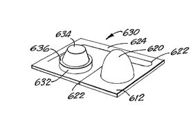
An alternative embodiment of the present
invention will now be discussed with reference to Figs.
31-36. In accordance with this alternative embodiment, a
container 500 is provided with a reclosable outlet ~orming
structure 510. More specifically, the outlet ~ormer
structure 510 comprises a curvilinear dome or mound 530
and a dual purpose punch/plug 520. As will be apparent to
one of skill in the art, the container 500 includes a
hole, not shown, over which the mound 530 is secured.
Because the punch/plug 520 must be lifted and inverted for
insertion into the scored area 532, it must not be sealed
to the container 500. On the other hand, the mound 530
portion of the outlet ~orming structure 510 must be
securely adhered over the hole in the container 500.
As can best be seen in Fig. 34, the outlet
forming structure 510 comprises a layer o~ ~oil 534
laminated to the plastic forming the outlet forming
structure S10. The portion of the ~oil 534 underneath the
mound 530 should be unsupported other than the adhesive
used to secure it to the mound 530. It should also be
noted that the foil 534 is secured to the container 500,
about the hole in the container 500, so that the contents
do not leak out beneath the outlet forming structure ~10.
The foil laminated adhesive should be one that gives
adequate adhesion but sets up with min~m~l tensile
strength of its own. In alternative embodiments, the
adhesive may approach being brittle.
The mound 530 further includes a fault line
pattern or scored pattern 532. The ~ault lines 532 may
take on any number of patterns, such as those shown in
Figs. 29a-d. As shown in Figs. 35 and 36, the foil 534 is
laminated to the entire sur~ace of the mound 530 and
preferably, is not scored. In an alternative embodiment,
.
CA 02243962 1998-07-21
W O 97/27~43 PCTrUS97/01137
- 39 -
the adhesive may be omitted ~rom the fault line pattern
532.
The punch/plug 520 is secured to the outlet
~orming structure 51Q via a tether 524. The tether 524 is
created by a cut 522 through the ~oil/plastic laminate.
As can best be seen in Fig. 32, the cut 522 pre~erably
takes a curvilinear path, ~ollowing the periphery of the
outlet ~orming structure 510. Such a cut 522 provides an
elongated tether 524.
In operation, the punch/plug 520 is ~irmly
pushed into the ~ault line pattern 532 to rupture the
scored mound 530. This operation is best shown in Fig.
35. Having ~orced the punch/plug 520 through the scored
area 532 o~ the mound 530, an opening for dispensing the
contents o~ the container 500 is ~ormed. The punch/plug
520 is removed ~rom the mound 530 so that contents o~ the
container 500 may be dispensed. Because the scored area
532 has been de~ormed to the shape o~ the punch/plug 520,
the punch/plug 520 may be reinserted into the scored area
532, thereby resealing the container 500.
In an alternative embodiment, however, the ~oil
layer 534 may span the hollow base o~ the mound 530 by
being laminated only to the periphery of the mound. O~
course, in such an embodiment, the punch/plug 520 must be
long enough to extend past the plane o~ the Eoil 534 so
that the ~oil 534 may be punctured. By wobbling the
punch/plug 520 while inserted into the mound 530, the
opening in the ~oil is enlarged.
It should be noted that the mound 530
strengthens the outlet Eorming structure 510.
- Furthermore, the shape o~ the mound 530 provides a nozzle
~unction, directing the contents o~ the cont~;ne~ 500 in
an even stream. Depending upon the contents o~ the
container 500, the ~;men~ions and shape o~ the mound 530
may be altered to provide the desired ~low.
CA 02243962 1998-07-21
W O 97/27043 PCT~US97/01137
- 40 -
The outlet forming structure 510 of Figs. 31-36
are preferably manufactured with a punch similar to that
described with re~erence to Fig. 12b. Of course, the tip
of the punch need not be spherical, but rather may be
elliptical, parabolic, or any curvilinear shape.
Furthermore, it i8 pre~erred that the foil and plastic be
laminated into a single web prior to the formation o~ the
mound be the punch. Thus, the ~m~nsions of the mound, as
defined by the shape o~ the punch tip, will be limited
only be the physical properties o~ the materials used.
In an alternative embodiment, which will now be
described with re~erence to Figs. 37-38, a reclosable
outlet forming structure 610 according to the present
invention is utilized with a flexible plasti-foil pouch
600. In general, the foil pouch 600 is formed by folding
a generally recta~gular shaped piece of the ~oil plastic
combination in half and sealing the three open edges
thereo~. A reclosable outlet forming structure 610 is
mounted on the seamless end 605 o~ the pouch 600. The
outlet forming structure 610, which is sealed to the
seamless end of the pouch 600 by applying an adhesive
around a periphery of the base 612, covers a hole, not
shown, in the pouch 600.
The outlet forming structure 610 may be of any
type previously disclosed above, such as those described
with reference to Figs. 1-3, 8-9, 13, and 13a. In a
preferred embodiment, as shown in Figs. 37 and 38, the
outlet forming structure 610 includes an aperture fonming
protrusion 630. More speci~ically, the aperture ~orming
protrusion 630 includes a hollow cylindrical base 632 and
a break-away tip 634. A fault line 636 extends around the
periphery of the protrusion struc~ure 630, permitting the
breakaway tips 634 to be broken away from the base 632 in
the tip 634. More specifically, the fault line 636 is a
= narrowed, stress concentrating area.
CA 02243962 1998-07-21
W O 97/27043 PCTrUS97/01137
- 41 -
The outlet ~orming structure 610 also includes a
cap 620. The cap 620 is a hollow tapered member, which
has an inside base diameter slightly larger than the
outside diameter o~ the base 632 o~ the protrusion
structure 630. The cap 620 is secured to the outlet
~orming structure 610 via a tether 624. The tether 624 is
~ormed by a cut 622 through the lower sur~ace 612 o~ the
outlet ~orming structure 610. As can best be seen in Fig.
39, the curvilinear cut 622 separates the cap 620 ~rom the
protrusion structure 630 and ~ollows the periphery o~ the
base 612. By having such a pattern, the cut 622 is
relatively long and, conse~uently, produces a relatively
long tether 624. ~ue to the long tether 624 and the fact
that the portion o~ the base 612 that supports the cap 620
is not ~astened to the pouch 600, the cap 620 may be
raised and securely placed over the outlet ~orming
structure 630.
In operation, a user applies sidewise ~inger
pressure to the protrusion tip 634, thereby causing it to
break away ~rom the protrusion base 632 along a ~ault line
636. Because the protrusion structure 630 is
substantially hollow, an aperture, not shown, is created.
Furthermore, because the protrusion member 630 has been
a~ixed to the pouch 600 over a hole in the pouch, not
shown, the contents o~ the pouch 600 may be dispensed via
the now opened protrusion neck 632. The cap 620 is placed
over the base 632 during shipping, so that accidental
rupturing o~ the ~ault line 636 is prevented.
FurthPrm~re, cap 620 is placed over the base 632 to
reclose the package 600 when only a portion o~ the
~ contents o~ the package 600 has been dispensed.
In an alternative embodiment, shown in Fig. 39,
~ the same outlet ~orming structure 610 is secured to the
side o~ pouch 640. In this embodiment, the pouch 640 is
~ormed from two generally rectangular sheets o~ ~oil
plastic laminate which are sealed together around all ~our
CA 02243962 1998-07-21
W O 97/27043 PCTrUS97/01137
sides of each sheet. As with the previous embodiment, the
protrusion structure 630 is affixed to the pouch 640 over
a hole, not shown, so the protrusion neck 632 is in ~luid
c~mmllnication with the contents of the pouch 640.
An alternative embodiment of the present
invention employing an outle-t forming structure 610a
disposed on a foil pouch 640a will now be described with
reference to Figures 37a, 38a, and 39a. Briefly
described, the outlet forming structure 610a is
substantial the same as the outlet forming structure
described with reference to Figures 37-39. Specifically,
the outlet forming structure 610a includes both a cap 620a
and a protrusion member 630a. As best seen in Figure 39a,
the foil pouch 640a includes a lap seam on the side
opposite the outlet ~orming structure 610a.
An alternative embodiment of the present
invention will now be described with reference to Fig. 40.
A tethered punch/plug and base member with a star shaped
fault pattern manu~actured as a unit 700 is shown. A
tether 730 is connected to the base 710 at a pr~;m~l end
thereof, a ring structure 740 connected to a distal end
thereof, and a tapered punch/plug 760. The punch/plug 760
i8 manufactured separately from the other components.
As shown, the ring structure 740 defines an
opening 750. The opening 750 is larger than the tip 762
of the punch/plug 760 yet smaller than the base 764 of the
punch/plug 760. Furthermore, the punch/plug 760 includes
a circum~erential indentation 766. The indentation 766 is
formed on the punch/plug 760 just below a point where the
outside diameter of the punch/plug 760 becomes larger than
the inside diameter of the opening 750.
Therefore, once the components have been
separately manufactured, the punch/plug 760 is snapped
into the opening 750. When snapped into the opening 750,
the tapered punch/plug 760 causes the slightly elastic
ring structure 740 to expand until the ring ~tructure 740
CA 02243962 l998-07-2l
W O 97/27043 PCT~US97/01137
- 43 -
reaches the indentatlon 766. Upon reaching the
indentation 766, the ring structure 740 snaps into the
indentation 766. Consequently, the punch/plug 760 becomes
connected to the ring structure 740 and the other
components.
In use, as shown in Figure 4Oa, the punch/plug
760 is used to puncture the scored section 722 o~ the
protrusion structure 720. Such operation is described in
greater detail with re~erence to Figs. 28-3Od.
Turning now to Fig. 41, one embodiment ~or
manufacturing a reclosable outlet ~orming structure
according to the present invention is shown.
Specifically, a pair of reclosable outlet ~orming
structures 870 and 880 are ~ormed ~rom the same piece o~
thermoplastic web F. Each reclosable outlet ~orming
structure 870, 880 comprises a protrusion structure 872,
882 as well as cap 874, 884, respectively. As in the
previously disclosed embodiments, each cap 874, 884 is
connected to the corresponding protruding structure 870,
880 via a tether 876, 886.
It is to be understood that the mating, horse-
shoe arrangement o~ the outlet ~orming structures 870, 880
provides several bene~its, such as reclining wasted
portions o~ the web F, and that the manufacturing
agreement may be repeated along the length o~ the web F.
Turning now to Figures 42-44, an alternative
embodiment o~ the present invention is shown. Initially,
it should be noted that the container 1000 shown is made
o~ similar materials as described above with re~erence to
Figure 1-3.
The container 1000 comprises a ~irst de~ormable
pouch 1010 and a second de~ormable 1020. The two pouches
1010, 1020 are joined by a shallow conduit 1030. The
de~ormable pouches 1010, 1020, as well as the joining
conduit 1030, are sealed by a general~y flat sheet 1040 o~
th~rm~ormable plastic material. A hollow protrusion 1050
CA 02243962 l99X-07-21
W O 97/27043 PCTAUS97/01137
- 44 -
is integrally formed with the flat sheet of thermoformable
plastic 1040. The hollow protrusion 1050 extends from the
flat sheet 1040. The protrusion 1050 is directly above
and in fluid c~mm~ln~cation with the conduit 1030. The
container 1000 further includes a punch/cap 1060.
As can best be seen in Figure 43, the hollow
protrusion 1050 has scores or fault lines 1055 on the top
face thereof. Despite these fault lines 1055, which
weaken the protrusion 1050, the container 1000 remains
sealed. Further shown in Figure 46, the punch/cap 1060 is
partially separated from the remainder of the container
1000 ~y cut 1062. The cut 1062 which parallels one
peripheral edge o~ the container 1000 creates a tether
1064.
In order to open the container 1000, the
punch/cap 1060 is positioned over the protrusion 1050.
The punch/cap 1060, and more specifically the pointed end
1066 of the punch/cap 1060 is forced through the score or
fault lines 1055, thereby opening the hollow protrusion
1050. When punch/cap 1060 is removed from the hollow
protrusion 1050, an opening, not shown, exists. The
opening is formed by the permanent deformation of the
portion of the protrusion member 1050 between the fault
lines 1055. By inverting the container 1000 and gently
squeezing either or both of the pouches 1010, 1020 the
material contained within the pouches i8 dispensed via the
opening in the protrusion 1050.
It should be noted that in the preferred
embodiment the protrusion 1050 is placed directly above
the conduit 1030. As a result, the contents of the
pouches 1010, 1020 can be dispensed in a controlled
m~nn~r. Specifically, the shallow conduit 1030 provides
resistance to the flowing contents so that the contents do
not spout from the opened protrusion 1050 uncontrollably,
particularly when the protrusion 1050 is initially
punctured.
CA 02243962 l998-07-2l
W O 97/27043 PCTAJS97/01137
- 45 -
As shown in Figure 44, should less than all o~
the material contained within the pouch 1010, 1020 be
dispensed, the cont~; ner 1000 may be reclosed.
Speci~ically, the punch/cap 1060 is inverted by twisting
the tether 1064. Because the punch/cap 1060 is hollow,
having an inside diameter substantially the same as or
slightly larger than the outside diameter o~ the
protrusion 1050, the punch/cap 1060 can be securely placed
on the protrusion 1050.
With regard to the embodiment o~ Figures 42-44,
it will be apparent to one skilled in the art that the
invention is not limited by the type o~ outlet ~orming
structure utilized. Speci~ically, any combination o~
break away tip, scored protrusion member, punch, plug, and
cap may be employed. Furthermore, it should be understood
that the particular shape o~ the pouches may vary
according to the properties o~ the contents held therein.
An alternative embodiment o~ the present
invention will now be described with re~erence to Figures
45-47. As shown in Figure 45, an outlet ~orming structure
1070 comprises a cap member 1072 and an aperture ~orming
protrusion 1074. As with the embodiments discussed above,
the cap member 1072 is connected to the aperture ~orming
structure 1074 by a tether 1076. As can be seen, both the
cap member 1072 and the aperture ~orming structure 1074
are ~ormed in a curvilinear base 1078.
Because the outlet ~orming structure 1070 is
~ormed in a curvilinear base 1078, it may be positioned on
a container 1080 having a similar curvilinear sur~ace. As
shown in Figures 46a-c, one such container 1080 is
generally spherical and ~ormed in two halves 1082, 1084.
The two halves 1082, 1084 are joined at one point along
~ their circum~erences, and are there~ore hingeably
connected. One hal~ 1084 o~ the container 1080 includes
an aperture 1086 ~ormed therein.
CA 02243962 1998-07-21
W O 97/27~43 PCTnUS97/01137
- 46 -
In operation, as shown in Figure 47, the outlet
i~orming structure 1070 iS a:Efixed to the container 1080
such that the aperture ~orming structure 1074 iS in
alignment with the aperture 1086 in the container 1080.
As ~urther depicted in Figure 47, the cap member 1072,
shown in a sectional view, may be positioned over the
aperture ~orming structure 1074, thereby protecting it and
sealing the container 180. It is to be understood that
the shape o~ the container 1080 is merely representative
o~ those that may be employed with the present invention,
as the outlet ~orming structure may be ~ormed on a
curvilinear base having virtually any shape.
Another alternative embodiment o~ the present
invention will now be described with re~erence to Figures
1~ 48-51. The container 1090 generally comprises a
rectangular sheet 1091 of thermo~ormable material. At the
center o~ the rectangular sheet 1091 is an aperture
~orming structure 1092, having a base and break away tip
as described above with reference to the prior
embodiments. On either side o~ the aperture ~orming
structure 1092 are pouches 1098 ~ormed on the underside o~
the sheet 1091 ~or holding any ~lowable substance. The
pouches 1098 are in ~luid c~mm-ln;cation with the aperture
~orming structure 1092.
Also ~ormed in the rectangular sheet 1091 of
thermo~ormable material is a cap member 1094. The cap
member 1094 is pre~erably formed in one corner o~ the
rectangular sheet 1091 and attached to the container 1090
via a tether 1096. The tether 1096 is ~ormed by a cut
1097 extending along the perimeter o~ the container 1090.
The cont~'n~r 1090 may be ~olded generally in
hal~ along bending grooves 2006 disposed on either side o~
the aperture ~orming structure 1092. Speci~ically, the
ends o~ the container 1090 are brought together as
3~ depicted by arrows "A" in Figure 49. Once the ends are
brought together, a ~emale package tie 2000 and a male
CA 02243962 1998-07-21
W O 97/27043 PCTrUS97/01137
package tie 2002, both of which are integrally formed in
the sheet o~ thermoformable material 1091, are brought
into engagement.
Engagement of the female package tie 2000 and
the male package tie 2002 hold the container 1090 in the
configuration as shown in Figures 50 and 51. In
operation, lateral finger pressure on the tip of the
aperture ~orming structure 1092 causes a fault line to
rupture, thereby forming an aperture in the aperture
forming structure 1092. Thus, the contents of the
contalner 1090 may be dispensed from the aperture. As
shown in Figure 51, the cap member 1094 may be placed over
the aperture forming structure 1092, thereby preventing
accidental rupturing of the fault line or accidental
dispensing of the contents after the tip of the aperture
forming structure 1092 has been removed.
Another alternative embodiment of the present
invention will now be described with reference to Figures
52-54. As shown in Figure 52, an aperture forming
structure 2016 according to the present invention may be
positioned on a treated paper board tube 2012, thereby
forming a sealed container 2010. The aperture forming
structure 2016 comprises a generally hollow frusto-conical
portion 2018, a hollow cylindrical portion 2019, and a
breakaway tip 2020. Integrally formed with the aperture
forming structure 2016 is a cap member 2022 and an
associated tether 2024. As can best be seen in Figure 54,
the tether 2024 is formed by a curvilinear cut which
allows the cap member 2022 to be partially separated ~rom
the aperture forming structure 2016 so that the cap member
2022 may be positioned over the cylindrical portion 2019
and the breakaway tip 2020. Because the cap member 2022
has an inside diameter slightly larger than the outside
diameter of the cylindrical portion 2019, the cap member
2022 fits snugly thereon, thereby sealing the cont~' n~
2010.
CA 02243962 1998-07-21
W O 97/27043 PCTAUS97/01137
- 48 -
As with the previously described embodiments, in
operation, lateral pressure on the breakaway tip 2020
causes it to separate ~rom the rest o~ the aperture
forminy structure 2016, thereby ~orming an aperture into
the generally hollow aperture ~orming structure 2016.
Thus, the contents o~ the container 2010 may be dispensed
there~rom.
It will remain understood by those skilled in
the art that the present invention in its broader aspects
is not limited to the particular embodiments shown and
described herein, and that variations may be made without
departing from the principles o~ the invention and without
sacri~icing its chie~ advantages.