Note: Descriptions are shown in the official language in which they were submitted.
CA 02244028 1998-09-08
POWER TRAIN SYSTEM FOR A VEHICLE
AND ME~IOD FOR OPERATING SAME
BACKGROUND OF THE INVENTION
1. Field of the Invention
The present invention relates to a power train system for a vehicle incorporating
an engine and a motor. The invention also relates to a method for controlling a power
train system.
2. Description of the Relateq Art
In recent years, an automatic engine stopping and starting apparatus (h~re;l~le
referred to as an "economy running system") has been known for stopping an engine
after a running vehicle has been stopped and restarting the engine if conditions for
driving the vehicle have been satisfied again. Japanese Patent Laid-Open No. 9-39613,
for example, discloses a structure of the above-mentioned apparatus in which a motor
generator is connected to an engine through a power distributing mech~ni~m The
automatic engine stopping and starting apparatus is arranged such that fuel supply to
the engine is interrupted while the vehicle is stopped, resulting in reduced fuel
consumption. Moreover, idle rotation of the engine is maintained by the motor
generator during the operation of the automatic engine stopping and starting apparatus
(hereinafter referred to an "economy running mode"). The engine is kept to have idle
rotation by the motor generator while the vehicle is stopped in order to operate auxiliary
machines, such as a co~ ,ssor for an air conditioner and a pump for a power steering
unit during such period.
The above-mentioned structure eliminates the need of electric motors to operate
the auxiliary machines, such as the compressor for the air conditioner and the pump for
the power steering unit. Thus, the space required for the structure of the economy
running system can be minimized.
CA 02244028 1998-09-08
However, the above-mentioned art to operate the auxiliary machines by
maintaining revolution of the engine at the idle speed cannot reduce power
consumption of the motor generator for operating the engine. Since the motor
generator is, in general, operated by electric power of a battery mounted on the vehicle,
5 power consumption of the battery is increased due to frequent stop operations of the
vehicle. As a result, a battery having a large storage capacity must be mounted on the
vehicle.
SUMMARY OF THE INVENTION
In view of the foregoing, an object of the present invention is to operate a motor
10 with smaller electric power when a vehicle is stopped.
To achieve the above-mentioned object, according to a first aspect of the
present invention, there is provided a connection switching unit disposed between the
drive shaft of the engine and a rotational shaft of the motor to enable/disable power
tr~n~mi~sion between the drive shaft of the en8ine and the rotational shaft of the motor,
15 and a tr~nsmi~sion controller that controls a function of the connection switching unit
for enabling/disabling power tr~n~mis~ion.
According to a second aspect of the present invention, there is provided a powertrain system for a vehicle having an engine and a motor connected to a drive shaft of the
engine including a tr~n~mission mechanism disposed between the engine and the motor
20 and capable of transmitting rotation of the rotational shaft of the motor to the drive shaft
of the engine at a changed speed, and an auxiliary machine connected to the rotational
shaft of the motor and operated by the engine or the motor. The tr~n~mi~ion
mechanism reduces the speed of rotation of the rotational shaft of the motor andtransmits rotation to the drive shaft of the engine when the auxiliary machine is
25 operated by the motor in a state where the engine is stopped.
According to the first aspect of the present invention, when, for example, the
auxiliary machine is operated by a motor while the engine is stopped, control isperformed such that rotation of the rotational shaft of the motor is not transmitted to the
drive shaft of the engine. Thus, only the auxiliary machine is operated by the motor
30 without operating the engine. Therefore, electric power required for the motor can be
reduced.
According to the second aspect of the present invention, when the engine is
started by the motor, the rotational speed of the rotational shaft of the motor is changed
-2 -
CA 02244028 1998-09-08
and the changed rotation is transmitted to the drive shaft of the engine. Therefore,
sufficient torque can be obtained from the motor, thus reducing the size of the motor.
Assuming that the auxiliary machine is operated by the motor when the engine is
stopped, it may be controlled to prevent rotation of the rotational shaft of the motor
S from being transmitted to the drive shaft of the engine and to drive only the auxiliary
machine without driving the engine. As a result, electric power required for the motor
can be reduced.
The second aspect of the present invention may be structured such that when the
auxiliary machine is operated by the motor while the engine is stopped, the transmitting
10 mechanism may interrupt the tr~n~mis~ion of rotation of the rotational shaft of the
motor to the drive shaft of the engine.
The first and second aspect of the present invention may have a structure in
which the connection switching unit is formed as an electromagnetic clutch for
switching a mechanical connection/disconnection between the drive shaft of the engine
15 and the rotational shaft of the motor.
The power train system according to the first or second aspect of the present
invention may have a structure in which another power generator is connected to the
drive shaft of the engine. The motor may be formed as a so-called motor generator
equipped with a power generating mechanism.
According to the second aspect of the present invention, the power train system
may further include first and second rotative members having rotational shafts disposed
in parallel with the drive shaft of the engine, a first cover joined to the engine to form a
first space in association with the engine for accommodating the first rotative member,
a second cover joined to an outside of the first cover to form a second space in25 association with the first cover for accommodating the second rotative member, a
motor rotative member provided for the rotational shaft of the motor so as to be rotated
in conjunction therewith, and a power tr~n~mi~ion that connects the motor rotative
member to either the first rotative member or the second rotative member such that
power can be transmitted. The motor rotative member and the power tr~nsmission are
30 accommodated in either the first space or the second space. As a result of the above-
mentioned structure, the rotative member of the motor and the first and second rotative
members provided for the drive shaft of the engine are connected with each other by the
power transmission. The rotative members and the power tr~n~mi~ion are
-3-
CA 02244028 1998-09-08
accommodated in a space defined by the body of the engine and the first cover or the
second cover joined to the body of the engine. Therefore, the motor can be mounted
without considerably ch~n~ing the structure of a conventional engine. The foregoing
structure may be arranged such that the first and second spaces are allowed to
co""l.unicate with each other and formed into spaces isolated from the outside portion
of the engine, and lubricant may be supplied into the first and second spaces. The
lubricant may be the one used to lubricate the engine and allowed to circulate to and
from the engine.
According to a second aspect of the present invention, there is provided a
10 method for operating a power train system for a vehicle including an engine operable in
an economy running mode, an electrically powered motor generator, an auxiliary
machine that receives power from at least one of the engine and the motor generator,
and a clutch between the engine and the motor generator, the method supplying power
to the auxiliary machine from the motor generator when the economy running mode is
15 selected, and disabling the clutch to prevent power from being transferred from the
motor generator to the engine when operating in the economy running mode.
These and other aspects will be described in or apparent from the following
detailed description of preferred embodiments.
BRIEF DESCRIPTION OF THE DRAWINGS
Preferred embodiments of the pr¢sent invention will be described in detail with
reference to the following drawings where like reference numbers indicate like parts, in
which:
F~G. 1 is a diagram showing a system of a power train system according to a
first embodiment of the present invention;
F~G. 2 is a diagram showing a system of a power train system according to a
second embodiment of the present invention;
FIG. 3 is a diagram showing a system of a power train system according to a
third embodiment of the present invention;
FIG. 4 is a diagram showing a system of a power train system according to a
30 fourth embodiment of the present invention;
FIG. 5 is a diagram showing a system of a power train svstem according to a
fifth embodiment of the present invention;
CA 02244028 1998-09-08
F~G. 6 is a diagram showing detailed structures of a motor generator, a reducinggear and a mounting structure according to the fifth embodiment of the present
invention;
F~G. 7 is a schematic view showing a planetary gear unit according to the fifth
embodiment of the present invention; and
F~G. 8 is a schematic view showing the system of the fifth embodiment of the
present invention.
DETAILED DESCRIPTION OF PREFERRED EMBODIMENTS
Embodiments of the present invention will now be described with reference to
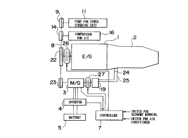
10 the drawings. F~G. I is a diagram showing the system of a power train system
according to a first embodiment of the present invention.
Referring to FIG. 1, an engine 1 is mounted on a vehicle including an automatic
transmission 2 (hereinafter referred to as an "A/T"), and a motor generator 3
(hereinafter referred to as an "M/G") serves as a motor and a power generator. The
15 M/G 3 is connected to a crank shaft of the engine 1 through a pulley 23, a belt 8 and a
pulley 22. An electromagnetic clutch 26 for enabling or disabling electric power supply
is disposed between the pulley 23 and the crank shaft of the engine 1. The M/G 3 is
connected to an oil pump 19 for the A/T 2 through an electromagnetic clutch 27. An oil
inlet pipe 24 is connected to the oil pump 19. An oil outlet pipe 25 is provided for the
20 oil pump 19. Auxiliary machines I 1 and 16, such as a pump for a power steering unit
and a compressor for an air conditioner, are also provided. The auxiliary machines 11
and 16 are connected to the crank shaft of the engine 1 and the M/G 3 through pulleys 9
and 14 and the belt 8, respectively. Other auxiliary machines, such as an oil pump and
a water pump for the engine 1 (not shown) are connected to the crank shaft and the M/G
25 3. An inverter 4 is electrically connected to the M/G 3. The inverter 4 performs a
switching operation to vary the amount of electric energy which is supplied from a
battery S serving as a power source to the M/G 3 so as to control the number of
revolutions of the M/G 3. Moreover, the inverter 4 performs a switching operation to
charge electric energy supplied from the M/G 3 to the battery 5. A controller 7 controls
30 engagement/disengagement of the electromagnetic clutches 26, 27 and the switching
operation of the inverter 4. The controller 7 receives input signals, such as a signal
indicating the number of revolutions of the M/G 3, a switching signal for selecting the
CA 02244028 1998-09-08
economy running mode and a switching signal for operating the air conditioner. Note
that lines shown in F~G. 1 and each having an arrow indicate signal lines.
The operation of the first embodiment will now be described. Initially, the M/G
3 is operated to start the engine 1. After starting the engine 1, the M/G 3 acts as a power
5 generator for storing electric energy in the battery 5. It is preferable to perform the
operation for charging electric energy at braking of a vehicle. When the engine is
started, the controller 7 detects the number of revolutions of the M/G 3. Moreover, the
controller 7 causes the inverter 4 to perform a switching operation such that a torque
and the number of revolutions required to start the engine I are realized. If a signal for
10 switching the air conditioner has been turned ON at starting of the engine, a higher
torque is required compared with the OFF state of the air conditioner. Therefore, the
controller 7 applies, to the inverter 4, a switching control signal to allow the M/G 3 to
rotate at a higher torque with a large number of revolutions. The switching control
signal to be output may be determined such that a variety of status signals of the engine
15 1, the A/T 2 and the vehicle are extracted to the controller 7 so as to be collated with a
map memory stored therein. Alternatively, the switching control signal may be
determined by calculations performed by a calculating unit disposed in the controller 7.
When the engine is started, the electromagnetic clutches 26, 27 are connected.
When an economy-running-mode signal is turned ON while the vehicle is
20 stopped, the controller 7 stops the engine 1 by transmitting a signal for interrupting fuel
supply to the engine 1. Note that a line for transmitting the signal for interrupting the
fuel supply is omitted from FIG. 1. The economy-running-mode signal is applied to the
controller 7, for example, by a driver who depresses a switch disposed in the inside of
the vehicle. The economy running operation can be performed at the economy running
25 mode under condition where, for example, the vehicle speed is zero and the shift lever
is in the range D or range N. In the foregoing state, the controller 7 transmits, to the
electromagnetic clutch 26, a control signal for disconnection. Thus, no power istransmitted between the pulley 22 and the engine 1. On the other hand, the
electromagnetic clutch 27 is brought to a connected state to allow the M/G 3 to operate
30 the oil pump 19. This is because the starting clutch (not shown) disposed in the A/T 2 is
arranged to be immediately engaged for driving the vehicle smoothly upon re-starting
of the engine.
CA 02244028 1998-09-08
In the case where the air conditioner and the power steering are required to be
operated even if the engine 1 is stopped, the controller 7 applies, to the inverter 4, a
switching control signal to rotate the M/G 3 at the number of revolutions and the torque
corresponding to the loads of the pump 11 for a power steering unit, the compressor 16
S for the air conditioner and the oil pump 19 for the A/T 2. When the engine 1 is re-
started from a state where the vehicle is stopped, the electromagnetic clutches 26, 27
are connected to rotate the M/G 3 at arbitrary number of revolutions and torque.As described above, the power train system according to the first embodiment
has the structure to stop the engine 1 while the vehicle is stopped and to cause the M/G
3 to operate the pump 11 for a power steering unit and the compressor 16 for the air
conditioner. Thus, the power of the M/G 3 is not transmitted to the engine 1. The
power consumption can be reduced compared with a structure in which the M/G keeps
the engine at the idle speed for operating the compressor for the air conditioner and the
pump for the power steering. Since the M/G 3 also serves as the means for operating
15 the pump 11 for a power steering unit and the compressor 16 for the air conditioner, the
system can be simplified.
FIG. 2 is a diagram showing a second embodiment of the present invention.
The second embodiment is different from the first embodiment shown in FIG. 1 in that
a pulley 29 and the pulley 23 are disposed coaxially; an electromagnetic clutch 28 for
20 enabling/(li~ling power tr~nsmi.c~ion between the engine 1 and the M/G 3 is disposed
between the pulley 23 and the pulley 29; and a belt 30 is set between the pulley 22
disposed above the engine 1 and the pulley 29.
The auxiliary machines are operated at the economy running mode while the
engine is stopped similarly to those according to the first embodiment. Unlike the first
25 embodiment, the electromagnetic clutch 28 is disposed adjacent to the M/G 3 as
described above. Therefore the torque to be transmitted by the electromagnetic clutch
28 can be reduced because the pulley 22 does not have to be operated. Therefore, the
size, weight and the cost of the electromagnetic clutch 28 can be reduced. Since the
pulley 22 does not have to be operated, electric power required for the M/G 3 can be
30 reduced.
F~GS. 3 and 4 are diagrams showing third and fourth embodiments of the
present invention respectively. FIG. 3 shows a s~ucture in which reduction
mech~ni~m~ 33, 34, 35, a brake 31 and a clutch 32 are disposed between the M/G 3 and
CA 02244028 1998-09-08
the pulley 23 as shown in FIG. 1. F~G. 4 shows a structure in which the reduction
mech:~nicm.~ 33, 34, 35, the brake 31 and the clutch 32 are disposed between the M/G 3
and the pulley 23 as shown in FIG. 2. Note that reference numeral 33 represents a sun
gear, 34 represents a carrier and 35 represents a ring gear. When the M/G 3 cranks
5 (actuates) the engine 1, the brake 31 is turned ON and the clutch 32 is turned OFF.
Thus, the rotational force of the M/G 3 is transmitted at a decreased speed from the sun
gear 33 to the carrier 34. As a result, even if the size of each of the M/G 3 and the
inverter 4 is reduced, the force required to crank the engine 1 can be maintained.
Therefore, electric power required for the M/G 3 can be reduced.
When the pump 11 for a power steering unit and the compressor 16 for the air
conditioner as the auxiliary machines are operated by the M/G 3 while the engine 1 is
stopped, the brake 31 is turned OFF and the clutch 32 is turned ON. At this time, the
electromagnetic clutch 27 is brought to an engaged state and the electromagnetic clutch
26 (identical to the electromagnetic clutch 28 in the structure shown in F~G. 4) is
15 brought to a disengaged state. Thus, the M/G 3 and the pulley 23 are directly connected
with each other so that the number of revolutions required to operate the auxiliary
machines 11, 16 can be obtained.
When the M/G 3 is used as an electric generator or the auxiliary machines 11,
16 are operated while operating the engine 1, the brake 31 is turned OFF and the clutch
20 32 is brought to an engaged state. At this time, the electromagnetic clutch 27 is brought
to a disengaged state and the electromagnetic clutch 26 (identical to the
electromagnetic clutch 28 in the structure shown in FIG. 4) is brought to the engaged
state. Thus, the M/G 3 and the pulley 23 are directly connected with each other so that
the rotations of the pulley 23 are transmitted to the M/G 3 while maintaining the
25 rotational speed of the pulley 23.
F~GS. 5, 6, 7 and 8 are diagrams showing a fifth embodiment of the present
invention. FIG. S shows the system of the fifth embodiment. FIG. 6 is a cross sectional
view showing the detailed structures of the motor generator 3 and a reduction gear 15.
FIG. 7 is a schematic view showing the detailed structure of a planetary gear
30 mechanism when the reduction gear 15 is viewed from the axial direction. F~G. 8 is a
schematic view showing the system of the fifth embodiment.
Referring to F~G. 5, there is provided an engine I and an automatic transmission2 (hereinafter referred to as an "A/T") disposed adjacent to the engine 1. A motor
., ,. ~ . . , ~ , . ... ~ . . ..
CA 02244028 1998-09-08
generator 3 (hereinafter referred to as an "M/G") serves as a motor and an electric
generator. A crank shaft 17 as a drive shaft for the engine I and the rotational shaft of
the M/G 3 are disposed in parallel with and apart from each other. A reduction gear 15
is disposed between the M/G 3 and the crank shaft 17 so that rotation of the rotational
S shaft of the M/G 3 is reduced and transmitted to the crank shaft 17. A crank-side
sprocket 12 (a rotative member) is connected and secured to the crank shaft 17. An
M/G-side sprocket 13 is connected and secured to a rotative element of the reduction
gear 15. A chain 18 is set between the crank-side sprocket 12 and the M/G-side
sprocket 13.
F~G. S shows a pump I I for a power steering unit and a compressor 16 for an airconditioner, each of which is an auxiliary machine. A pulley 10 is directly connected to
the rotational shaft of the M/G 3. Pulleys 9 and 14 are secured to the respective ends of
the rotational shafts of the pump 11 for a power steering unit and the compressor 16 for
the air conditioner. A belt 8 is set among the pulleys 9, 10 and 14. The pulleys 9, 10, 14
and the belt 8, for example, constitute a power transmission means for transmitting
rotation of the M/G 3 to the auxiliary machines 11, 16. In FlG. 5, the structure seems to
show that the M/G-side sprocket 13 and the pulley 10 are coaxially and integrally
connected to the rotational shaft of the M/G 3. However, the M/G-side sprocket 13 and
the pulley 10 are not always rotated at the same speed as described later. The
tr~n~mi~ion of the rotational force is performed independently.
An inverter 4 is electrically connected to the M/G 3 and arranged to vary the
amount of electric energy to be supplied from a battery S as a power source to the M/G
3 so as to control the number of revolutions of the M/G 3. The inverter 4 also performs
control to store electric energy generated by the M/G 3 in the battery 5.
The M/G 3 is connected to an oil pump 19 for the AIT 2 through an
electromagnetic clutch 27. An oil inlet pipe 24 is connected to the oil pump 19. An oil
outlet pipe 25 i6 connected to the oil pump 19. The foregoing structure enables the M/G
3 to operate the oil pump 19 by bringing the electromagnetic clutch 27 to an engaged
state while the engine is stopped at the economy running mode. This is because the
starting clutch (not shown) disposed in the A/T 2 is arranged to be immediately
engaged for driving the vehicle smoothly upon re-start of the engine.
Referring to FIG. 5, a controller 7 transmits, to the inverter 4, a signal for
controlling the switching operation, ON-OFF control signals to the electromagnetic
. . ., ~. . ", , .. . ~ i ~. .... . . .. .. .
CA 02244028 1998-09-08
clutch 27 and ON-OFF control signals to the electromagnetic coil of the reduction gear
15 to be described later. The controller 7 receives a signal indicating the number of
revolutions of the M/G 3, a signal for switching the economy running mode, a signal for
switching the operation of the air conditioner, an engine status signal indicating, for
S example, the number of revolutions of the engine 1, a vehicle status signal (not shown)
indicating the vehicle speed and the like and a status signal (not shown) of the A/T 2
indicating the range selected by the shift lever. ~ accordance with information
indicated by the above-mentioned supplied signals, the controller 7 performs an
operation for reading data from a memory and a calculating operation. Then, the
10 controller 7 transmits arbitrary control signals to the reduction gear 15, the inverter 4,
the electromagnetic clutch 27 and the like. The controller 7 may be formed as a so-
called computer system provided with known units including a CPU, a RAM, a ROM, a
bi-directional communication bus, interface circuits (a signal conversion circuit and the
like) and an auxiliary memory.
The detailed structures of the M/G 3, the reduction gear 15 and a structure for
mounting the M/G 3 on the engine 1 will now be described with reference to FIG. 6.
One end of a casing 36 of the M/G 3 is secured to a bracket 38 of a cylinder block 37 of
the engine 1 with bolts 40 such that a rotational shaft 39 is in parallel with the crank
shaft 17 and the sprocket 13 secured to the rotative element of the reduction gear 15 is
flush with the crank-side sprocket 12 secured to the crank shaft 17. The other end of the
casing 36 is secured to extended first and second covers 64, 58 to be described later. In
this embodiment, the M/G 3 is secured to a portion opposite to the A/T 2 of the engine
1 and adjacent to a sprocket 82 for operating a cam shaft 81 in the engine 1 secured to
the crank shaft 17. A stator 41 is disposed in the casing 36 to surround a rotor 42. The
rotor 42 is rotatively disposed opposite to the stator 41. The rotational shaft 39 is
secured integrally with the rotor 42 for integral rotation. A radial bearing 43 is
provided for rotatively supporting the rotational shaft 39.
The reduction gear 15 connected to the rotational shaft 39 will now be describedwith reference to F~GS. 6 and 7. The reduction gear 15 has a planetary gear unitincluding a sun gear 45, a pinion gears 46, a ring gear 47 and a carrier 55 therein. The
sun gear 45 of the planetary gear unit is formed integrally with the rotational shaft 39.
Three pinion gears 46 are disposed on outer periphery of the rotational shaft 39 at the
same intervals of an angular degree of 120~ and engaged with the sun gear 45. The
-10-
CA 02244028 1998-09-08
relative positions among the three pinion gears 46 are kept unchanged. The threepinion gears 46 are able to turn around and move around the sun gear 45. Moreover,
each of the pinion gears 46 is rotatively disposed in the ring gear 47 such that the inner
periphery of the ring gear 47 is engaged with the pinion gear 46. A plate 48 spline-
5 engaged to prevent relative rotation with respect to the ring gear 47 is disposed on theouter periphery of the ring gear 47. An electromagnetic clutch 49 is disposed opposite
to the plate 48. The electromagnetic clutch 49 includes a coil 50 therein. When
energizing the coil 50, the electromagnetic clutch 49 attracts the plate 48 by
electromagnetic force. As a result, rotation of the ring gear 47 is inhibited. A one-way
clutch 51 is disposed between a portion of the rotational shaft 39 closer to the rotor 42
than the sun gear 45 and the ring gear 47. The one-way clutch 51 allows the ring gear to
rotate. The rotation of the ring gear 47 can be transmitted to the rotational shaft 39. On
the other hand, the rotation of the rotational shaft 39 cannot be transmitted to the ring
gear 47. It is controlled such that the speed of the rotational shaft 39 does not exceed
15 the rotational speed of the ring gear 47 that has been enabled to rotate.
The inside portion of the casing 36 is sectioned into two spaces by a partition
52. The stator 41 and the rotor 42 are accommodated in one of the spaces, while the
planetary gear unit, the one-way clutch 51, the electromagnetic clutch 49 and the plate
48 are accommodated in another space. The coil 50 of the electromagnetic clutch 49 is
20 secured to the partition 52. A signal for energizing the coil 50 is transmitted from the
controller 7. As shown in FIG. 6, a sealing member 53 is provided.
A carrier 55 is allowed to pass through each of the pinion gears 46 of the
planetary gear unit through a needle bearing 54. Each carrier 55 is rotatively provided
in the pinion gear 46. The carrier 55 is connected to a hollow rotative member 70 and
25 movable around the sun gear 45 and able to rotate about the sun gear 45 integrally
therewith such that the relative positions of the carriers 55 are m~int~ined. The hollow
rotative member 70 extends in the axial direction (to the left in the drawing) of the
rotational shaft 39 and has a spline formed on the outer periphery for engagement with
the M/G-side sprocket 13. The movement of the M/G-side sprocket 13 in the axial
30 direction of the hollow rotative member 70 is restricted by a nut 56. The M/G-side
sprocket 13 is connected to the crank-side sprocket 12 of the engine 1 through the chain
18. Thus, rotation between the crank shaft 17 and the rotational shaft 39 of the M/G 3
CA 02244028 1998-09-08
can be transmitted. A bearing 60 is provided for rotatively supporting the hollow
rotative member 70.
As shown in FIGS. 6 and 8, a sprocket (a rotative member) 82 for operating the
cam shaft 81 (see FIG. 8) of the engine 1 is secured to the crank shaft 17 at a position
5 closer to the body of the engine 1 than the crank-side sprocket 12. The cam shaft 81 is
disposed in paaallel with the crank shaft 17. A cam-shaft sprocket 80 is secured to the
cam shaft 81 to correspond to the sprocket 82 for operating the cam shaft 81. A chain
85 is provided between the sprocket 82 for operating the cam shaft 81 and the cam-shaft
sprocket 80. Thus, rotations of the crank shaft 17 are transmitted to the cam shaft 81.
The sprocket 82 for operating the cam shaft 81, the cam-shaft sprocket 80 and the chain
85 are disposed in a first space 63 defined by a cylinder block 37 and a first cover 64.
Engine lubricating oil is supplied to the first space 63 so as to be circulated in the first
space 63. The crank-side sprocket 12 for transmitting power between the M/G 3 and
crank shaft 17 is secured to the crank shaft 17 at a portion outside of the sprocket 82 for
operating the cam shaft 81 coaxially therewith. A second space 59 defined by the first
cover 64 and the second cover 58 attached to the outside of the first cover 64
accommodates the crank-side sprocket 12, the M/G-side sprocket 13 and the chain 18.
The first space 63 and the second space 59 communicate with each other so that
lubricating oil supplied from the engine 1 is sufficiently supplied into the second space
59. The first cover 64 and the second cover 58 extend toward the ~/G 3. Three
portions (only one portion is illustrated) of a cover 68 are secured to the first cover 64
with bolts 65. Another portion of the cover 68 is secured to the first and second covers
64 and 58 with a bolt 67. Lubricating oil circulated to the first space 63 and the second
space 59 is supplied through a pipe (not shown) and dropping for lubricating required
portions. Lubricating oil is supplied to the planetary gear unit through a pipe (not
shown) for lubricating each portion of the planetary gear unit, and then allowed to pass
through the inside portion of the hollow rotative member 70. Then the lubricating oil is
returned from the second space 59 to an oil pan (not shown) where it is mixed with oil
which has been dropped after lubricating the other portions of the engine.
The rotational shaft 39 penetrates the hollow rotative member 70 and the
second cover 58 to project to the outside portion. The pulley 10 for driving theauxiliary machines is secured to the rotational shaft 39 by spline engagement, such that
CA 02244028 1998-09-08
the rotational shaft 39 and the pulley 10 can be integrally rotated. A sealing member 61
is disposed between the second cover 56 and the pulley 10.
FIG. 7 is a schematic cross sectional view showing the planetary gear unit when
it is viewed from the axial direction of the rotational shaft 39. The relative positions of
S the sun gear 45, the pinion gears 46, the ring gear 47 and the carrier SS can easily be
understood from F~G. 7.
The operation of the fifth embodiment will now be described. When the
economy running mode has been started by application of an ON signal for switching
the economy running switch on, fuel supply to the engine 1 is interrupted if
10 predetermined conditions are satisfied. Thus, the engine I is stopped. At this time, an
ON signal is transmitted from the controller 7 to the electromagnetic clutch 27 which is
brought to an ON state. Since the pump 11 for a power steering unit and the
compressor 16 for air conditioner as the auxiliary machines are required to be operated
while the engine 1 is stopped, electric energy of the battery S is supplied to the M/G 3
15 for rotation. The rotation of the M/G 3 is controlled by the controller 7 and the inverter
4. At this time, the controller 7 transmits an OFF signal to the electromagnetic clutch
49 in the reduction gear l S to allow the ring gear 47 of the planetary gear unit to rotate.
When the rotational shaft 39 of the MIG 3 is rotated as shown in FIG. 6, the
pulley 10 rotated integrally with the rotational shaft 39 drives the auxiliary machines
20 11, 16. On the other hand, the one-way clutch S l prevents transmission of the rotation
of the rotational shaft 39 to the ring gear 47. Since the carrier SS is stopped by a sliding
resistance of the engine 1 while the ring gear 47 is allowed to rotate, the pinion gears 46
only turn around without moving around the sun gear which is turning around. (the ring
gear 47 inversely rotates around the sun gear 45 as the pinion gears 46 rotate). Thus,
25 only the auxiliary machines are operated by the M/G 3. Therefore, the auxiliary
machines can be operated with small electric power without operating the engine 1.
When the engine 1 is re-started at the economy running mode, the controller 7
transmits an ON signal to the electromagnetic clutch 49 of the reduction gear l S to
prevent the rotation of the ring gear 47. When the rotational shaft 39 of the M/G 3 is
30 rotated in the foregoing state, the rotation of the sun gear 45 is transmitted to the pinion
gears 46. Sir ce the rotation of the ring gear 47 is prevented, the pinion gears 46 move
around the sun gear 45 while turning around by themselves. Thus, the carrier SS in each
pinion gear 46 moves around the sun gear 45 so that the hollow rotative member 70 and
CA 02244028 1998-09-08
the M/G-side sprocket 13 are rotated coaxially with the rotational shaft 39. At this
time, the rotational speed of the M/G-side sprocket 13 is obtained by reducing the
rotational speed of the rotational shaft 39 at a reduction ratio which is determined by the
number of teeth of the sun gear 45 and that of the pinion gears 46. Therefore a
5 sufficiently high torque for actuation is transmitted from the M/G 3 to the engine 1
because of the reduced speed of the sprockets 12, 13. Thus, the engine 1 is re-started.
This leads to an effect of reducing the size of the M/G 3. The auxiliary machines 11,16
are operated by the M/G 3 in synchronization with rotation of the rotational shaft 39.
When the power of the engine 1 or the kinetic energy of the vehicle is attempted10 to be recovered as electric energy while operating the engine or braking the vehicle, the
rotation of the crank shaft 17 is transmitted to the M/G-side sprocket 13. Thus, the
carrier 55 is rotated. At this time, the controller 7 transmits an OFF signal to the
electromagnetic clutch 49 so that the ring gear 47 is brought to a rotative state.
Although the rotational shaft 39 is caused to be stopped by a load generated in
15 conjunction with electric power generation, the rotation of the carrier 55 causes the
pinion gears 46 to turn and move around. Thus, ring gear 47 is rotated at an accelerated
speed. Then, the one-way clutch 51 transmits the rotation of the ring gear 47 to the
rotational shaft 39. Since the carrier 55 and the ring gear 47 integrally rotate about the
sun gear 45, the rotation of the crank shaft 17 is transmitted to the M/G-side sprocket 13
20 and the rotational shaft 39 at the same speed. At this time, the rotational shaft 39 is
rotated to cause the auxiliary machines 11,16 to be operated and the M/G 3 to generate
electric power simultaneously.
Since this embodiment is structured such that the portions corresponding to the
clutches 26,28 are contained in the reduction gear 15, the whole size can be reduced by
25 elimin~ting these clutches 26, 28 as compared with the third embodiment.
This embodiment has the structure in which the second space 59 (a space
projecting over the body of the engine 1) for accommodating the power transmission
means (the chain 18) between the M/G 3 and the engine I is defined by the cylinder
block 37, the first cover 64 and the second cover 58. The shape of the cylinder block
30 37, thus, is not required to be changed, resulting in cost reduction. The lubricating oil
for the engine 1 can be used for circulation. Since the crank shaft 17 and the M/G 3 are
connected with each other by the chain 18, excellent effect can be obtained in that
-14-
CA 02244028 1998-09-08
power transmission can reliably be performed and noise generated during the operation
can be reduced.
Although each of the first to fourth embodiments have the structure in which thepower of the engine and that of the motor can be transmitted through the chain and the
sprocket, another method may be employed. For example, connection using pulleys
and belts, connection using gears and another connection method may be employed.In the first to fourth embodiments, if it is structured such that the air conditioner
is operated by the MJG 3 while the engine 1 is stopped, the compressor for the air
conditioner does not have to be operated by the engine I at an idle state of the engine
10 (revolutions in a poor fuel economy region) while the vehicle is stopped. Thecompressor 16 for air conditioner is rotated by the M/G 3 at the economy running mode
while the engine 1 is stopped. The electric energy obtained from the battery 5 is
recovered by operating the M/G 3 as an electric generator in a revolution region of the
engine 1 where an excellent fuel efficiency can be realized during operation of the
15 engine 1. Thus, the fuel efficiency of the vehicle can be further improved.
Since each of the first to fourth embodiments has the structure in which the
engine 1 is not operated by the M/G 3 while the engine 1 is stopped, electric power
required for the M/G 3 can be reduced. Thus, reduction in power consumption of the
battery 5 can be realized.
While the present invention has been described with reference to what are
presently considered to be plcfcllcd embodiments thereof, it is to be understood that the
invention is not limited to the disclosed embodiments or constructions. On the
contrary, the invention is intended to cover various modifications and equivalent
arrangements. In addition, while the various elements of the disclosed invention are
25 shown in various combinations and configurations, which are exemplary, other
combinations and configurations, including more, less or only a single element or
embodiment, are also within the spirit and scope of the invention.