Note: Descriptions are shown in the official language in which they were submitted.
CA 02244066 1998-07-24
W O 97/27897 PCTrUS97101459
A DEVICE, SYSTEM AND METHOD FOR INTERSTITIAL
TRANSVASCU~AR lhl~KV~h ION
RELATED APPLICATIONS
This patent application is filed with a claim of
~ priority to United States Provisional Patent
Application Serial No. 60/010,614 filed on February 2,
1996, the entire disclosure of which is expressly
incorporated herein by reference.
Also, filed contemporaneously herewith are three
(3) separate applications entitled METHODS AND
APPARATUS FOR BLOCKIN& FLOW THROUGH BLOOD VESSELS,
METHODS AND APPARATUS FOR ANASTOMOSIS OF ANATOMICAL
CONDUITS, and CAl~l~S AND RELATED DEVICES FOR FORMING
PASSAGEWAYS BETWEEN BLOOD VESSELS OR OTHER ANATOMICAL
STRUCTURES, each of which includes subject matter which
was initially included in United States Provisional
Patent Application Serial No. 60/010,614 and claims
priority to that provisional application.
Background of the Invention
i. Percutaneous Transvascular Arterial Bypass
Atherosclerosis is a progressive disease process
in which the flow within the lumen of an artery becomes
restricted by-a blockage, typically referred to as an
atherosclerotic plaque. In the heart, as well as the
periphery, a blockage of an artery can result in pain,
disfunction and even death. Numerous methods have been
employed over the years to revascularize the tissue
downstream of an arterial blockage. These methods
include bypass grafting using artificial, in-situ
venous, or transplanted venous grafts, as well as
angioplasty, atherectomy and most recently, laser
transmyocardial revascularization. Bypass grafting has
been extremely successful; however, the procedure
requires extensive surgery. Recently, newer techniques
such as the transthoracic endoscopic procedure being
CA 02244066 1998-07-24
W O 97/27897 PCTrUS97/014S9
-2--
pursued by the companies, Heartport, Inc. and
Cardiothoracic Systems, Inc., illustrate the need for a
less invasive method of bypassing coronary vessels.
These procedures are very difficult to perform, and may '
not be widely applicable. While transmyocardial laser
revascularization, a technique in which small holes are
drilled through the wall of the heart, looks promising,
the method of action is not yet well understood, and
problems exist with the use of laser energy to create
the channels. Yet clinicians are still very interested
in the technique because it has the potential to be
minimally invasive, and does not require the patient to
be placed on cardiopulmonary bypass.
In the 1970s several cardiovascular surgeons
experimented with the use of cardiac veins for
revascularization. The procedure was for use on
patients which had severally diffuse stenotic coronary
vessels. ~he technique involved using an intervening
graft from the internal mAmm~ry artery or an aortic
attachment to a saphenous vein. Instead of sewing the
grafts to the distal coronary artery, the grafts were
attached to the coronary or cardiac vein in the same
location. The pro~imal portion of the vein was then
ligated to prevent a shunt, and the patient was then
taken off cardiopulmonary bypass, and the chest was
closed. In this model, the veins were "arterialized",
allowing flow in a retrograde fashion in an effort to
bring o~ygenated blood to the venules and capillaries
of the heart. The success of this technique varied
greatly, and was for the most part abandoned. Problems
included stenosis at the anastomosis, intracardiac
hemorrhages from ruptured venules, and thrombosis of
the grafts.
The devices, systems and methods proposed in this
disclosure suggest a new method of percutaneous
revascularization. Here, the cardiac veins may either
be arterialized, or may be simply used as bypass
CA 02244066 l998-07-24
W O 97/27897 PCTAUS97/01459
grafts. There is no literature to suggest that this
has ever been attempted. While in-situ bypass grafts
have been made in periphery, still an incision is made
- to attach and ligate the vein ends. Another procedure
which bears some resemblance to this technique is
~ called the TIPS procedure transjugular intrahepatic
portosystemic shunt. In this procedure a stent is
advanced into liver tissue to connect the portal vein
to the inferior vena cava. While this procedure can be
accomplished percutaneously, it is not for the purpose
of revascularization of an organ or to bypass a
blockage within a vessel, does not permit retrograde
flow within either of the two vessels, is not performed
with an accompanying embolization, and requires the use
of a stent. Further, the devices and methods used in
that setting are too large and do not have the
directional capability necessary for use in smaller
vessels such as those found in the heart.
ii. Transvascular Intervascular Interstitial Surgery
Open surgery was for many years the only way to
gain access to tissues to perform a surgical maneuver.
With the advent of optics, various endoscopic
procedures were developed. Initially, these procedures
utilized natural orifices such as the urinary tract,
oral cavity, nasal canal and anus. Most recently, new
techniques using transabdominal and transthoracic ports
have been developed. These thorascopic or laporoscopic
procedures essentially use instruments which are long
shafted versions of their counterparts in open surgery.
General anesthesia is usually required, and there are
still several smaller wounds which require healing.
Another problem that exists with this approach is
the identification of anatomically consistent reference
points. For precise surgery, such as in the brain, a
frame is usually attached to the patients head to
provide this reference. More recently, a /'frameless"
system has been developed which utilizes a much smaller
CA 02244066 1998-07-24
W 097/27897 PCT~US97/01459
frame mounted with several light emitting diodes
(LEDs~ The ~EDs are correlated to LEDs on the
instrument itself using three cameras mounted to the
ceiling. This aids in the correlation of the frame to
the landmarks, and assures proper positioning of the
instrument. While this seems like an extensive effort,
it underlines the importance o~ gaining access to the
exact location desired.
Traditionally, the vascular system has been
entered for the sole purpose of addressing a vascular
problem. Angioplasty, atherectomy, stents, laser
angioplasty, thrombolysis and even intracardiac biopsy
devices have all been designated for intravascular use.
iii. Intraluminal Closure _
To date, there are several available schemes for
closing off openings, vessels or tubular structures
within the body involved in, for instance, the
revascularization process. One method utilizes
externally applied apparatuses such as staples, clips,
sutures or devices which compress the opening
e~ternally and apply energy to weld them shut, for
example, the Keppinger Forceps. While these methods
are very successful, they all require access to the
structure ~rom the outside. However, this may not
always be possible during certain catheter based
inventions.
Another method, compatible with the catheter
approach, involves the application of intralllm; n~l
devices such as detachable coils, balloons, injectable
glues or emboli. These solutions are all limited by
the requirement that a foreign object must be used to
create a blockage. Moreover, the presences of a
foreign object within the body, may at a later time,
cause other problems. For example, these devices may
become dislodged, or may cause a sever tissue reaction
which can be of significant concern.
CA 02244066 1998-07-24
W O 97/27897 PCT~US97/014~9
Summary of the Invention
A device, system and method are provided for
utilizing the vascular system as a conduit through
~ which an intervention can be rendered within and beyond
the vascular wall. In accordance with one embodiment,
~ a device is introduced into the vascular system at a
convenient entry point and is advanced to a particular
target location at which point an opening is created to
allow the passage of the device or another device or
devices through or around the port into the space
beyond the interior of the vessel. In one embodiment,
a system is used to act as an access port to the space
through which a procedure may be performed. Such a
procedure may be worthwhile for cooling or ablating a
volume of tissue, injecting or infusing a drug,
substance or material, cutting, manipulating or
retrieving tissue, providing access for endoscopic
visualization or diagnosis, the placement of an
implantable or temporary device, creating an
alternative tract through which blood may be conducted
for the purpose of revascularization or for performing
some other surgical procedure. In another embodiment,
the system is used to achieve an extraliminal
percutaneous bypass. More particularly, the system is
used to simultaneously achieve a second opening in an
adjacent vessel proximate to the first opening so that
an anastomosis channel may be created between the two
vessels or conduits for the passage of blood
therethrough. Such a procedure may be useful for
creating alternative vascular channels to provide
alternative revascularization routes, such as in the
heart between the coronary arteries and cardiac veins,
or in the periphery between adjacent veins, conduits
and/or arteries. In one embodiment of the invention,
the vessel with the second opening may be an in-situ
vessel, a natural or artificial graft segment, or a
transplanted vessel, all of which having been joined to
CA 02244066 1998-07-24
W O 97/27897 PCTAUS97/014~9
the vessel with the first opening in a side-to-side
manner. In other words, the two adjacent vessels, each
having a substantially same size opening created by the
system, may be maintained in approximation in a
relatively parallel manner rather than the conventional
end-to-side manner. With further specificity, such a
system may be used to bypass coronary arteries and
provide for cardiac venous arterialization, or
segmental grafting. In addition, the stabi~ity of
vascular supply orientation to anatomic landmarks
provides a simple method of repeatedly accessing
perivascular structures under imaging or other
guidance. This may be particularly useful for
accessing areas within the brain, kidney, lung, liver,
spleen as well as in other tissues, and represents a
significant advantage over tissue marking localization,
external frames or so-called "frameless" external
instrument orientation systems. In a further
embodiment, the system is used to create an opening in
the vessel proximally, tunneling through the tissue
adjacent to the vessel, and re-entering the vessel at a
distal point. This may be useful for providing an
alternate path for blood flow around a lesion with a
vessel. A final embodiment of the invention includes a
system for closing off an opening such as a lumen of a
vessel subse~uent to the creation of an alternate
revascularization route through which blood may flow
around a diseased lesion. The system may use a suction
mechanism to first pull the walls of the vessel so that
the lumen may be temporarily closed. The system then
provides means to securely fix the walls against one
another to close off the lumen.
In accordance with one particular embodiment of
the invention, there are provided methods and devices
for transmyocardial revascularization, whereby
transmyocardial passageways or bore holes are formed
between one or more coronary blood vessels and one or
CA 02244066 1998-07-24
W 097/27897 PCT~US97/01459
more chambers of the heart, such that blood from the
chamber(s) of the heart will flow through the
transmyocardial passageways, thereby enhancing the
perfusion of that region of the myocardium. In some
instances, this may be accomplished by passing a
~ passageway-forming catheter of the present invention
through the coronary sinus and into a coronary vein.
Thereafter, the passageway-forming catheter is utilized
to form a plurality of transmyocardial passageways or
bore holes from the coronary vein into a chamber of the
left heart, preferably the left ventricle. Thereafter,
the passageway-forming catheter is removed and the
coronary vein is permitted to remain without occlusion,
embolization or ligation, such that o~ygenated blood
from the left the left ventricle will flow freely
through the transmyocardial passageways, through the
coronary vein, and back into the coronary sinus. In
this manner, a continual and unobstructed flow of
arterial blood will be permitted to pass from the left
ventricle, through the transmyocardial passageways,
thereby providing for enhanced oxygenation and
profusion of that region of the myocardium.
Brief Description of the Drawin~s
Figure 1 is an anterior, perspective view of a
human heart wherein catheters have been inserted to
perform a translumenal coronary revascularization
procedure wherein a segment of coronary vein is
utilized as a bypass conduit for bypassing an
obstruction in a coronary artery.
Figure la is an enlarged, sectional view of the
adjacent coronary artery and coronary vein within
segment la of Figure 1.
Figure 2 is an enlarged, partial sectional view
through a portion of the heart shown in Figure 1.
Figure 3a is a perspective view of a passageway-
forming catheter apparatus of the present invention
CA 02244066 1998-07-24
W O 97/27897 PCT~US97/0~459
-8-
having a first embodiment of an orientation marker
system formed thereon.
Figure 3b is a perspective view of the catheter
shown in Figure 3a, wherein the catheter has been
rotated ninety degrees relative to the showing of
Figure 3a.
Figure 3c is a perspective view of another
passageway-forming catheter of the present invention
having a second embodiment of an orientation marking
scheme formed thereon.
Figure 3d is a perspective view of the catheter of
Figure 3c, wherein the catheter has been rotated ninety
degrees relative to the showing of Figure 3c.
Figure 3e is a cross sectional view through
another catheter of the present invention having a
third embodiment of an orientation marking system
formed thereon.
Figure 3f is a partial perspective view of the
catheter shown in Figure 3e, wherein the catheter has
been rotated approximately forty-five degrees relative
to the showing of Figure 3e.
Figure 4 is a perspective view of a procedure for
attaching a bypass graft to a coronary artery, in
accordance with the present invention.
Figure 5 is an enlarged view of the distal portion
of a passageway-forming probe apparatus utilized to
form a passageway and connection between the graft and
the coronary artery in the procedure shown in Figure 4.
Figure 6 is an enlarged cut away perspective view
of segment 6 of Figure 4.
Figure 6a is an enlarged view of the passageway
and connection formed between the gra~t and the
coronary artery in the procedure of Figure 4.
Figure 7 is a perspective view of a portion of the
human thorax showing a method for performing a
m; n;m~l ly invasive in situ bypass procedure to bypass
CA 02244066 1998-07-24
W O 97/27897 PCT~US97tO1459
an obstruction in a coronary or peripheral blood
vessel.
Figure 8 is a perspective cut away view of an
adjacent artery and vein having an introducer and
access catheter of the present invention inserted
A thereinto for use in performing an in situ bypass
procedure whereby blood from one of the blood vessels
is caused to flow into the lumen of the other blood
vessel.
Figure 9 is a cut away perspective showing of the
final result of either an in situ bypass or bypass
grafting procedure, in accordance with the present
invention.
Figure 10 is a longitudinal sectional view of two
adjacent blood vessels having a blood flow passageway
formed therebetween in accordance with the present
invention, and a lumen blocking apparatus disposed
within the lumen of the bypass vessel to facilitate the
flow of shunted blood in the desired direction through
the bypass vessel.
Figure lla is a longitudinal sectional showing of
a delivery catheter having a self expanding
embolization device in the nature of a gel foam sponge
positioned within the lumen of the catheter, and
advanced over a prepositioned guide wire.
Figure llb shows the catheter of Figure lla
wherein the self expanding embolization device in the
nature of a gel foam sponge is being advanced out of
the distal end of the catheter and over the guide wire.
Figure 12a is a perspective view of a one way
valved stent apparatus which is usable to facilitate
one way flow through the passageways formed between
blood vessels or other anatomical structures, in
accordance with the methods of the present invention.
Figure 12b is a side view of the apparatus of
Figure 12a.
CA 02244066 l998-07-24
Wo 97/27897 pcT~us97/ol4ss
--10--
Figure 13 is a longitudinal sectional view of
adjacent blood vessels having a blood flow passageway
or anastomosis channel formed therebetween in
accordance with the present invention, and having a
5 protrusive stent disposed within the passageway or
channel and extending into the lumens of the blood
vessels, such protrusive stent being optionally ~ormed,
wholly or in part, of a relatively dense material which
will block the natural flow of blood through the lumen
lO of at least one of the blood vessels.
Figure 14 is a longitudinal perspective view of
adjacent blood vessels having a blood flow passageway
(i.e., an anastomosis channel) formed therebetween and
having a non-protrusive stent mounted within the blood
15 flow passageway (i.e., an anastomosis channel) to
maintain the dimensions of the blood flow passageway
(i.e., an anastomosis channel).
Figure 15 is a longitudinal sectional view of
adjacent blood vessels having a blood flow passageway
20 or an anastomosis channel formed therebetween in
accordance with the present invention, such blood ~1OW
passageway or anastomosis channel being dilated by a
balloon which has been advanced over a guide wire ~or
the purpose of dilating the passageway or an
25 anastomosis channel.
Figure 16 is a longitudinal sectional showing of
two adjacent blood vessels having an initial puncture
tract or channel formed therebetween in accordance with
the present invention, and further showing an energy
30 emitting vaporization catheter being advanced over a
guide wire which has been passed through the initially
created puncture tract or channel, such vaporizing
catheter being operable to form a :Einished blood
passageway or an anastomosis channel having the desired
35 dimensions.
Figure 17 is a longitudinal sectional showing of
an adjacent blood vessels having a blood flow
CA 02244066 1998-07-24
W O 97/27897 PCTrUS97/01459
passageway or anastomosis channel formed therebetween
in accordance with the present invention, and wherein a
welding catheter system of the present invention is
~ used to weld or fuse the tissue which surrounds the
blood flow passageway or anastomosis channel, thereby
~ establishing a firm connection between the openings
formed in the adjacently situated blood vessels.
Figure 18 is a longitudinal sectional view of
adjacent blood vessels having a blood flow passageway
or an anastomosis channel formed therebetween in
accordance with the present invention, and having a
polymer stent covering the walls of the passageway or
an anastomosis channel.
Figure 19 is a longitudinal sectional showing of
adjacent blood vessels having a blood flow passageway
or anastomosis channel formed therebetween, and having
a stapling catheter of the present invention positioned
within such passageway or channel to install staples to
connect the blood vessels and hold the passageway or
channel in the desired alignment.
Figures l9a-19c show, in step-wise fashion, the
manner in which the stapling catheter of Figure 19 is
utilized to install the staples within the blood flow
passageway or anastomosis channel.
Figure 20 is a longitudinal sectional view to
adjacent blood vessels having a blood flow passageway
or anastomosis channel formed therebetween, and having
a clip-installing catheter device of the present
invention passed through the passageway or anastomosis
channel to install a clip therewithin.
Figure 20a is a longitudinal section view of the
blood vessels shown in Figure 20, having a clip of the
present invention installed within the blood flow
passageway or anastomosis channel formed between the
blood vessels.
Figure 21 is a longitudinal sectional showing of
adjacent blood vessels having a blood flow passageway
CA 02244066 1998-07-24
W 097/27897 PCTrUS97/01459
-12-
or anastomosis channel of the present invention formed
therebetween, and an alternative embodiment of a
welding catheter device passed through such passageway
or channel to fuse or weld or tissue surrounding the
channel.
Figure 22 is a longitudinal sectional showing of
an adjacent coronary artery and coronary vein, wherein
an in-situ coronary bypass procedure of the present
invention has been completed.
Figure 23a is a longitudinal sectional view of a
blood vessel wherein a TVIS access port of the present
invention has been percutaneously inserted.
Figure 23b is a longitudinal sectional showing of
a blood vessel having another embodiment of a TVIS
access port o~ the present invention, which includes an
optional balloon, inserted thereinto.
Figure 24 is a longitudinal sectional showing of a
blood vessel having a TVIS guide catheter of the
present invention positioned therewithin, and a TVIS
device ~i.e., passageway forming catheter) advanced
through such guide catheter.
Figure 25 is a perspective view of another
embodiment of a TVIS catheter of the present invention,
having an active imaging component formed or mounted
thereon.
Figure 26 is a longitudinal section showing of
adjacent blood vessels having an initial puncture tract
formed therebetween and a catheter borne retrograde
tissue cutting assembly of the present invention
positioned therewithin to enlarge the initial puncture
tract to form the desired anastomosis channel or blood
flow passageway.
Figures 27 is a longitudinal sectional showing of
a blood vessel having another embodiment of a TVIS
guide catheter incorporating proximal and distal
isolation balloons.
CA 02244066 1998-07-24
W O 97/27897 PCT~US97/01459
-13-
Figure 28a is a longitudinal sectional showing of
an obstructed artery and an ad~acent area of tissue,
with a TVIS guide catheter and TVIS device of the
present invention being advanced through the adjacent
tissue to form an interstitial tunnel or blood flow
passageway around the obstruction.
Figure 28b is a longitudinal sectional showing of
the blood vessel of Figure 28a, following formation of
the interstitial tunnel around the obstruction.
Figure 29a is a sectional showing of a coronary
blood vessel and an adjacent segment of myocardium,
wherein a TVIS catheter or probe of the present
invention have been advanced into the coronary blood
vessel and is being used to form an interstitial
channel in the myocardium to enhance perfusion of that
region of the myocardium.
Figure 29b is a sectional showing of a coronary
blood vessel and an ad~acent segment of myocardium,
wherein an alternative TVIS catheter or probe of the
present invention have been advanced into the coronary
blood vessel and is being used to form an interstitial
channel in the myocardium to enhance perfusion of that
region of the myocardium.
Figure 29c is a sectional showing of a ~ifurcated
coronary blood vessel wherein a TVIS catheter of the
present invention has been positioned, such TVIS
catheter being utilized to form a series of
interstitial channels to enhance perfusion of that
region of the myocardium.
Figure 29d is sectional showing of a coronary vein
and an adiacent segment of myocardium which forms a
wall of the left ventricle of the heart, and a series
of transmyocardial blood flow passageways having been
formed between the coronary vein and the left ventricle
in accordance with the present invention, and the
coronary vein r~m~ ng unobstructed and unlighted such
that oxygenated blood may flow from the left ventricle,
CA 02244066 1998-07-24
W O 97/27897 PCT~US97/01459
through the transmyocardial channels, through the
coronary vein and into the coronary sinus thereby
providing for continual enhanced per~usion o~ that
region of the myocardium.
Figure 2~d' is a longitudinal sectional view
through the coronary vein shown in Figure 29d.
Figure 30 is a longitudinal section showing of a
blood vessel having a TVIS catheter and ancillary
devices positioned therewith in accordance with the
present invention.
Figure 3la is a longitudinal sectional view of a
portion of TVIS catheter o~ the present invention
having a locking guide wire passed therethrough.
Figure 31b is a perspective showing of the locking
guide wire apparatus shown in Figure 3la.
Figure 32a is a perspective showing of a portion
of a TVIS catheter of the present invention having a
deflectable or curvable distal portion.
Figure 32b is a plan view of the TVIS catheter of
Figure 32a in a non-curved, straight configuration.
Figure 33a is a longitudinal perspective showing
of adjacent blood vessels wherein an alternative TVIS
catheter device of the present invention is being
utilized to form a passageway or anastomosis channel
between the blood vessels by emission of a vaporizing
energy beam.
Figure 33b is a longitudinal perspective showing
of adjacent blood vessels having an initial puncture
tract or passageway formed therebetween, and a device
of the present invention passed therethrough for
widening or enlargement of the initial puncture tract
or channel.
Figure 34a is a longitudinal sectional view o~ the
distal tip of a TVIS catheter device of the present
invention having a tissue-penetrating probe formed of
shaped memory material retracted thereinto.
CA 02244066 1998-07-24
W 097/27897 PCT~US97/01459
Figure 34b is a longitudinal sectional showing of
adjacent blood vessels having the TVIS catheter of
Figure 34a advanced thereto, and showing the shaped
memory tissue-penetrating probe being advanced out of
the distal end of the catheter to form an initial
puncture tract or passageway between the blood vessels.
Detailed Description of the Preferred Em~odiment
The invention herein utilizes the vascular system
as a perfect conduit to any region of the body. The
devices, system s and methods described herein provide
a new way that the interstitial space can be accessed
for surgical purposes. The invention described herein
provides a system for gaining percutaneous access to
any part of the body through the vascular system, and
provides the basic set of instrumentation for
accomplishing several surgical and medical end points.
The present invention provides a percutaneous
means for revascularizing an organ fed by a diseased
vessel. In accordance with further embodiments of the
present invention, a complete multiple coronary artery
bypass may be accomplished without cracking open the
chest, general anesthesia or cardiopulmonary bypass.
In order to provide an overall understanding of
the present invention, the method of the invention will
be discussed with reference to the device's use to
bypass a lesion within the coronary artery in the heart
percutaneously. However, it will be understood by
persons of ordinary skill in the art that the general
method, system and device as described herein are
equally applicable to the surgical manipulation of any
perivascular structures. This invention represents a
new concept in minimally invasive surgery which is that
the vascular system may be used purely as a conduit to
a desired surgical point. Under the proper guidance,
at that surgical point, the perivascular space can be
penetrated by a device so as to allow for the insertion
CA 02244066 1998-07-24
W O 97/27897 PCTrUS97/01459
-16-
of various instrumentation to create a surgical effect.
Some examples of these procedures may include but are
not limited to: transvascular intracranial access and
subsequent therapeutic or diagnostic intervention to
various perivascular tumors, hemorrhages, stroke
affected areas and diseased zones; transvascular tissue
biopsies from the brain, heart, kidney, liver, lung or
bone; transvascular implantation of drugs, materials or
devices such as sensors, radioactive seeds,
ferromagnetic particles, balloons, cells or genetic
material, and transvascular bypass.
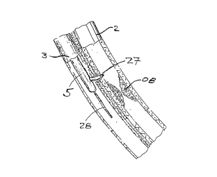
Referring to Figure 1, a typical coronary sinus
guide catheter 4 is shown having been advanced up the
vena cava 7 and into the heart 1. Although not shown,
the guide catheter 4 has been advanced into the
coronary sinus within the right atrium of the heart 1.
This guide catheter 4 will be of the type generally
known in the art to include a tip o~ sufficient
compliance and size to assure a traumatic insertion
into the coronary sinus, with a balloon at its distal
end to permit the retrograde injection of contrast to
permit imaging of the cardiac venous system. The
transvascular interstitial ~TVIS) guide catheter 5 is
inserted through the guide catheter 4 and advanced
through one cardiac vein 3 over a guide wire 28 to a
desired point adjacent to a coronary artery 2. The
figure shows a TVIS probe 27 being advanced through the
TVIS guide catheter 5 through an opening in the cardiac
vein 3 to a desired point in the coronary artery 2.
Figure 2 shows, in more detail, the various
functions and components which could be included on the
TVIS guide catheter 5. Here the TVIS guide catheter 5
is shown within a cardiac vein 3 being advanced over
guide wire 28. A balloon 21 is provided on TVIS guide
catheter 5 ~or the purpose of blocking flow,
stabilizing the catheter within the lumen, or dilating
the passageway. TVIS guide catheter 5 is also provided
CA 02244066 l998-07-24
W O 97/27897. PCT~US97/01459
with either or both active orientation detection means
23 and passive orientation detection means 22. The
passive orientation means 22 may be configured of any
of a known set of materials which would allow ~or the
radiographic, fluoroscopic, magnetic, sonographic or
electromagnetic detection of the position and
orientation of the distal portion of the TVIS guide
catheter 5 within the body. These materials include
but are not limited to any radiopaque material such as
barium or steel, any ferromagnetic material such as
those with iron, or any material or composite which
provides sufficient interference to sound waves such as
trapped air bubbles, scored metal or several laminates.
The active orientation detection means 23 permits the
proper 360 degree orientation of the distal portion on
the TVIS guide catheter 5 within the lumen of the
vessel, in this case cardiac vein 3. This active
orientation means 23 can utilize any one but is not
limited to one of the following technological schemes:
the active orientation means 23 may be a simple piezo-
electric, wire or silicon based slab capable of sending
and receiving a signal to detect the presence or
velocity of flow within an adjacent vessel; this same
device could be an array of receivers in relation to a
transmitter for the purposes of providing an image of
the surrounding tissue; this same device could also be
a simple transmitter capable of sending a signal to
guide wire 202 positioned in this case within the
coronary artery 2 where guide wire 202 is further
modified to include a small receiver/transmitter 203
and wire bundle 204 capable of returning a signal to
the operator upon detection of the signal emitted by
active orientation means 23; the reverse system is also
applicable where the small receiver/transmitter 203
sends a signal to active orientation means 23; the same
could also be said for orientation means 23 to send or
receive signals to or from any of a series of known
CA 02244066 1998-07-24
W O 97/27897 PCTAUS97/01459
-18-
signal generators including sonic, electromagnetic,
light or radiation signals. The TVIS guide catheter 5
is provided in this case with an additional opening to
allow for the selective injection of contrast or fluid
into the vessel, in this case cardiac vein 3. Once the
orientation of the TVIS guide catheter 5 is assured,
the TVIS probe 27 and TVIS sheath 26 may be advanced
through the wall of the cardiac vein 3 into the
interstitial space 29 and into the coronary artery 2.
The TVIS probe 27 and TVIS sheath 26 do not necessarily
need to be advanced simultaneously and may have the
following configurations: the TVIS sheath 26 may be a
sharp tipped or semi rigid cannula capable of being
inserted into the tissue alone; the TVIS probe 27 may
be a relatively rigid wire, antenna, light guide or
energy guide capable of being inserted into the tissue
alone with the support of TVIS sheath 26; or further
the TVIS probe 27 and TVIS sheath 26 may be operatively
linked where the two are inserted together into the
tissue. The TVIS probe 27 and/or the TVIS sheath 26
provide the initial connection between the two vessels,
the cardiac vein 3 and coronary artery 2. In one
embodiment of the invention, the TVIS sheath 26 may be
made from stainless steel, nitinol or a polymer
material. Once the TVIS sheath 26 is placed, a more
floppy guide wire can be placed through it to permit
the advancement of additional instrumentation in the
case where another lumen is to be entered.
Alternatively, no guide wire may be necessary if the
interstitial space is being entered to perform a
different type of procedure. This procedure may be
used to create a bypass path from coronary artery 2
around a coronary stenosis 201, into the cardiac vein 3
and in some cases, back into the coronary artery 2. To
further ensure accurate formation of a bypass path
across two adjacent vessels, for example, a coronary
artery to a cardiac vein, a catheter which has been
CA 02244066 1998-07-24
W O 97/27897 PCT~US97/014~9
-79-
inserted into one of the two vessels may be provided
with a plurality of passive orientation detection means
shown in Figure 2 to correctly orient the direction of
a TVIS probe. By way of example, each of the passive
orientation detection means 4200 and 4201, as shown in
- Figure 3a, may be situated on opposite sides of
catheter 4202. In a preferred embodiment, detection
means 4200 and 4201 are placed along a diameter across
catheter 4202. In this manner, when the catheter 4202
is rotated about axis Z and the passive orientation
detection means 4200 and 4201 subsequently become
correspondingly aligned relative to one another, as
seen in Figure 3b, TVIS probe 4203 may be properly
oriented within one vessel (not shown) so as to later
forma bypass path across the adjacent vessels.
Moreover, the passive orientation detection means 4200
and 4201 are positioned on catheter 4202 in such a
manner that when viewed from the perspective of Figure
3~ (i.e., when the passive orientation detection means
are in corresponding alignment with one another) they
are in linear alignment with a distal portion 4204 of
TVIS probe 4203 along axis Z.
In an alternate embodiment, the passive
orientation detection means may be configured with a
design as shown in Figures 42c and 42d. As
illustrated, passive orientation detection means may
comprise a substantially circular portion 4205 and a
portion 4206 diametrically situated across catheter
4202. In other words, portion 4206 and the center of
circular portion 4205 are situated along one diameter
across the catheter 4202. To properly align the TVIS
probe 4203 and its distal portion 4204 within a vessel
for bypass path formation across to an adjacent vessel,
catheter 4202 is rotated about the Z axis until portion
4206 and circular portion 4205 are concentrically
aligned when viewed from the perspective of Figure 3D.
CA 02244066 l998-07-24
W 097/27897 PCT~US97/01459
-20-
In a further embodiment, the passive orientation
detection means may be provided as shown in Figures 3e
and 3f to include a plurality of segments, for
instance, segments 4206 and 4207. When segments 4206
and 4207 are viewed from one end of catheter 4202, as
illustrated in Figure 3e, they are substantially
parallel along a diameter of catheter 4202. E~owever,
when looking at catheter 4202 from a side view, as seen
in Figure 3f, segments 4206 and 4207 are not
diametrically aligned as seen in Figures 3a and 3b.
Rather, these segments are offset from one another such
that when catheter 4202 is rotated about axis Z to
properly orient the TVIS probe (not shown~ within the
vessel, segments 4206 and 4207, and the distal portion
4204 of the TVIS probe are essentially aligned in
series.
Although only three different embodiments for the
passive orientation detection means are shown, it
should be appreciated that, for instance, other
geometrical designs may be provided on the catheter
such that when visualization of a particular geometry
occurs, it may be said that a proper orientation of the
TVIS probe has ~een achieved. Non-geometrical
embodiments may also be provided so long as such an
embodiment provides a proper orientation of the TVIS
probe to form a bypass path from within one vessel to
an adiacent vessel.
In accordance with a further embodiment of the
present invention, a bypass vessel, as illustrated in
Figure 4, may be attached to a coronary vessel with a
stenosis in a side-to-side manner so as to provide an
extraliminal percutaneous bypass path around the
coronary stenosis. To understand the particular
method, the discussion is provided with reference to
devices for generally performing an e~traliminal
percutaneous bypass of a coronary vessel or an arterial
. CA 02244066 1998-07-24
W O 97/27897 PCTrUS97/01459
vessel in the periphery using a graft segment, an in-
situ vessel or a transplanted vessel.
Figure 4 illustrates a procedure using an
artificial or biological graft segment to bypass either
a coronary vessel or an arterial vessel in the
periphery. An artificial or biological graft segment
3101 may be positioned against a vessel 3106 within the
body, and in this instance, in the heart 3107. Graft
segment 3101 may be made from an artificial material
such as PTFE or Dacron, or a biological material such
as m~m~ry artery, saphenous vein or other suitable
tubular conduit. As shown in Figure 4, a probe 3102
may be inserted through an entry point 3105 on graft
segment 3101~ Alternatively, probe 3102 may be
inserted either within graft segment 3101 through one
of its ends, or along side graft segment 3101 through a
side branch. Purse stringed sutures 3104 are
positioned about entry point 3105 to permit, upon
completion of the procedure, rapid closure of the hole
created by the entry point 3105. Probe 3102 is
positioned about entry point 3105 to permit, upon
completion of the procedure, rapid closure of the hole
created ~y the entry point 3105. Probe 3102 is
positioned within a body wall 3108 through port 3109
and has handle 3110 to permit control and modification
of tip 3103. Handle 3110 may be connected to a range
of external devices 3111 such as fluid
irrigation/suction, radio fre~uency (RF) energy,
ultrasound imaging hardware, doppler hardware,
endoscopic imaging apparatuses, other energy sources
such as microwaves or lasers, and mechanical actuation
means. The purpose of probe 3102 is to provide
mechanical support and, if necessary, to detect the
proper location for the graft to be placed. A grasper
3112 is also shown in Figure 4 assisting in the
placement and stabilization of the graft segment 3101.
Once positioned correctly, stay sutures or an
CA 02244066 l998-07-24
W 097/27897 PCTAUS97/01459
-22-
attachment agent 3113 such as a surgical adhesive may
be used to hold the graft in place against the vessel
3106 during subsequent maneuvers. Although the
procedure is discussed in connection with the heart, it
should be appreciated that the procedure is egually
applicable to arterial vessels in the periphery.
Figure 5 illustrates, in detail, the tip oi~ the
probe 3102 shown in Figure 4. Here a probe shaft is
shown terminating in a probe tip 3201. In one
embodiment of the invention, angle 3208, at which the
tip 3201 is positioned relative to the shaft 3207, may
be variable. Alternatively, the relative angle between
the tip 3201 and the shaft 3207 may be i~ixed. On the
tip 3201, detection means 3202 is positioned in or next
to (as shown) access means 3205. The detection means
3202 provides information about the correct positioning
of access means 3205 and may be a doppler imager or
detector, ultrasonic imager or detector, or other
detection means capable of sensing the presence of the
desired vascular structure, for instance, a vessel. In
cases where the vessel is clearly visible, such a
detection scheme may not be necessary. Nevertheless,
access means 3205 may be provided with a number of
configurations. The configuration shown in Figure 5
allows for a flexible sheath 3204 to be introduced over
the access means, and for a guide wire 3206 to be
introduced percutaneously from within. Alternatively,
a sharp wire could be used to access the vessel with a
flexible sheath over it, permitting the sharp wire to
be subsequently exchanged for a more a traumatic guide
wire. Figure 5 further shows graft 3203 in outline
around a probe shaft 32Q7 and tip 3201. Graft 3203, as
previously indicated, may be an artificial or
biological gra~t segment (or transplanted vessel ~rom a
nearby area). Once the probe within the graft 3203 is
properly positioned adjacently to a vessel with a
stenosis, access means 3205 is used to puncture
CA 02244066 l998-07-24
W 097/27897. PCTrUS97/01459
simultaneously through both the walls of the graft 3203
and the adjacent vessel similar size openings so as to
create a channel therebetween. The presence of such an
anastomosis channel is preferable as it permits a guide
S wire to be introduced between the graft and the vessel
so that the sizing of the channel and the attachment of
the graft to the vessel may subsequently be carried out
across the channel. It should be appreciated that any
artificial or biological graft segment (or transplanted
vessel from a nearby area) may be positioned over or
along side such structures as the femoral or popliteal
arteries or veins, the coronary arteries or veins, the
aorta, the carotid or iliac arteries, the vena cava, or
any other tubular structure within the body to perform
the indicated bypass.
Figure 6 shows, in accordance with a preferred
embodiment of the invention, a procedure for joining,
across an anastomosis channel 3305, two vessels in a
side-to-side manner for bypassing a stenosis. Graft
3300, which may be an artificial or biological segment,
or a transplanted vessel from a nearby area, may be
positioned against vessel 3307 using probe 3301, and
the scheme described in Figures 4 and 5. Graft 3300
may subsequently be affixed in place with an attachment
means, for instance, a surgical adhesive 3309. The
attachment means, for example, stay sutures, energy
based welding, glues, or magnetism may be used to hold
the two vessels in apposition. Since an artificial or
biological segment, or a transplanted vessel from a
near~y area is used as a ~ypass conduit in a side-to-
side procedure discussed herein, one or both ends of
graft 3300 may be terminated with a clip 3303 to
prevent leakage of flow therefrom. Over a guide wire
3306, an attachment delivery device 3302 is introduced
to junction 3308 between the graft 3300 and the vessel
3307 to deploy an attachment member thereat. One type
of attachment member useable for this purpose is an
CA 02244066 1998-07-24
W O 97/27897 PCT~US97/01459
-24-
anastomosis stent 3304 having a clover shape, a
complete description of which is set forth in copending
United States Patent Application Serial No. 08/730,327
filed on October 11, 1996 and claiming priority to
earlier filed Provisional Application Serial No.
60/005,164. Alternatively, other channel connector
devices may be used, such as those described in PCT
International Patent Application No. entitled
METHODS AND APPARATUS FOR CONNECTING OPENINGS FORMED IN
ADJACENT BLOOD VESSE~S OR OT~ER ANATOMICAL STRUC~URES,
which is being filed contemporaneously with this
application.
As illustrated in Figure 6a, the anastomosis stent
3304 or other channel connector device is used to
provide an extraliminal connection between the lumen of
vessel 3307 and the lumen of graft 3300. In addition,
stent 3304 is used to hold the vessel 3307 and the
graft 3300 in close approximation and to maintain the
size of the anastomosis channel 3305. However, it
should be appreciated that the attachment member (i.e.,
anastomosis stent) for maint~; n i ng the size of the
anastomosis channel may be any number of devices, for
instance, a stapler, an internal clipper, a stent, or a
welder.
Figures 7 and 8 illustrate an in situ bypass
procedure for a coronary vessel or an arterial vessel
in the periphery. In an in situ bypass procedure,
vessels 3405 and 3406, one of which is to be bypassed,
naturally lie in close proximity to one another, rather
than having been brought into that position.
Introducer 3400, as shown in Figure 7, is initially
inserted through port 3109, across the body wall 3108,
and into one of the two adjacent vessels 3405 and 3406.
An access catheter 3401 is thereafter introduced
throu~h introducer 3400 and manipulated so that its tip
3404 is threaded into a proper position within one of
the vessels, for example, vessel 3406. In one
CA 02244066 1998-07-24
W O 97127897 PCT~US97/01459
.
-25-
embodiment of the invention, access catheter 3401
includes a hub 3402 having a plurality of access ports
3403 so as to permit the introduction or removal of,
for example, various devices, energy delivery means, or
fluids and gasses.
- Figure 8 illustrates, in further detail, the
introducer 3400 and access catheter 3501 within vessel
3502 which is to be bypassed. Access catheter 3501,
similar to catheter 5 of Figure 2, is shown having an
optional balloon 3503, passive detection means 3504,
active detection means 3505, sheath 3506 and guide
wires 3507 and 3509. In this diagram, the guide wire
3509 has been substituted for a TVIS access probe 27
shown in Figure 2. The in-situ bypass procedure
discussed in connection herewith, is substantially
similar to the procedure set forth in connection with
Figures 4 and 5. In particular, the initial access
within a vessel is accomplished endoscopically.
Moreover, the isolation of an adjacently parallel
vessel, and the percutaneous procedures for creating an
anastomosis connection, and for attaching the vessels
are conducted in very much the same way. The essential
di~ference is that in an in-situ situation, a naturally
adjacent vessel is used as a bypass conduit rather than
an artificial or biological bypass segment. In
addition, with an in situ procedure, the use of the
active detection means to locate the bypassing vessel
may be much more critical, especially if the endoscopic
suite is not equipped with fluoroscopy.
Figure 9 illustrates an end result of a side-to-
side procedure for either an in situ bypass or a bypass
wi~h a grafting segment. In such a procedure, since
endoscopic access is readily available, the need for
intraluminal blockage to prevent shunting may not be
limited to the use of devices similar to an
embolization apparatus (a discussion of which is
provided hereinafter). Instead, both ends of vessel
CA 02244066 1998-07-24
W 097/27897 PCT~US97/01459
-26-
3609 may be closed off using parallel sutures 3607 as
shown. The parallel sutures 3607 may also be used to
isolate a portion of vessel 3609 within which a hole
3608 exists where the introducer had previously been
placed. As previously indicated, the introducer may
alternatively be placed directly into the end of the
graft 3609, rather than through side hole 3608~ in the
event an artificial or biological graft segment is
being used in the bypass procedure. As shown in Figure
10 9r by joining a bypass vessel 3609 in a side-to--side
manner to vessel 3600 which has a diseased lesion 3604~
a small tissue track, such as anastomosis channels 3602
may be created using, for example, a dilating balloon,
dissection and exposure, or endoscopic attachment as
described earlier. The creation of anastomosis channel
3602 allows for fluid to flow into the bypassing vessel
3609 from vessel 3600 at a proximal location bypassing
the lesion 3604. If it is desirable, another
anastomosis channel 3602 may be created downstream of
lesion 3604 SO that fluid may flow around the lesion
3604, and back into vessel 3600 at a distal location.
An anastomosis device 3603 may be used to maintain the
channel 3602 and to maintain the two vessels in
approximation. The vessels may also be maintained in
approximation by other attachment means indicated
above, or by welding the vessels against one another.
To prevent fluid such as coronary blood from
shunting directly back through the bypassing vessel
after the percutaneous creation of the anastomosis
channel for bypassing the stenosis, it may be necessary
to block flow at one or more points within the
bypassing vessel. With reference now being made to a
coronary bypass in Figure 10, once a hole is made
within cardiac vein 3, and it is determined that it is
of sufficient size, an embolization device, such as an
embolization balloon 33, can be used to block flow in
the cardiac vein 3 in a region proximal to anastomosis
CA 02244066 1998-07-24
W 097127897 PCTrUS97101459
-2?-
channel 36. This maneuver ensures that coronary
arterial flow 34 passes through anastomosis channel 36
and results in a retrograde cardiac venous flow
indicated by arrows 35a and 35b. The embolization
balloon 33 is placed using embolization catheter 31 and
upon proper inflation, is detached via a detachable
segment 32. Any one of several devices and materials
are available for the purpose of embolization. These
include detachable balloons, coils, strands of
coagulation producing material, microfibrillar
collagen, collagen sponge, cellulose gel or sponge such
as Gelfoam, or special stents. Figure 10 shows how
these devices can be used to re-arterialize the venous
system distal to the connection. However, as shown in
~5 Figure 12, it is possible to simply provide a bypass
path by performing the same procedure in reverse in an
appropriate downstream location. It should be
mentioned that these embolization devices may also be
used to block off any unwanted tributaries branching
off from the cardiac vein. Figures 4 and 9 are
described later in this document.
Figures lla-llb and 12a-12b depict two additional
schemes of embolization device in accordance with the
invention which also may have utility to accomplish the
desired closure. These embolization devices, as well
as others, are described in more detail in PCT
International Patent Application No
Pntitled METHODS AND APPARATUS FOR BLOCKING FLOW
THROUGH BLOOD VESSELS, which is being filed
contemporaneously with th1s application.
The embolization device shown in Figure lla is a
compressed collagen sponge 101 located within an outer
sheath 102, capable of being delivered over guide wire
51. Once the guide wire 51 is advanced into vessel
which is to embolized, outer sheath 102 is withdrawn
over inner core 103 to permit collagen sponge 101 to
e~pand into the vessel as seen in Figure llb. Once
CA 02244066 l998-07-24
W O 97127897 PCT~US97/014~9
-28-
completely delivered, the guide wire 51 and the
catheter assembly 102 and 103 are withdrawn, leaving
the sponge in place.
Figures 12a and 12b depict a one way valved stent
112. Membrane 111, disposed within the stent 112, is
configured to be cylindrical at side 116, yet collapsed
upon itself at side 113 to form a one way valve. As
seen in longitudinal section Figure 12b, this al~ows
flow in the direction of arrow 114 and the advancement
of devices in this direction, but prevents flow in the
direction of arrow 115 as well as preventing devices
from entering from that direction. The one way valve
stent 112 can be easily placed over a catheter into the
desired location and e~panded to fit in position. Once
the internal delivery catheters are removed, membrane
111 is allowed to collapse, instantly creating a valve
like action.
It will be appreciated that the use of the
collagen sponge 101 as shown in Figures lla and llb, or
flow blocking or partially flow blocking stents 112 as
shown in Figures 12a and 12b, are not the only means by
which the normal flow of blood through the bypass
vessel may be blocked. Indeed, certain energy emitting
devices and systems useable for intraluminal welding or
sealing of the vessel lumen (which were originally
shown in Figures 37-40 of Provisional Application
Serial No. 60/010,614 to which this application claims
priority) as well as other embolizers or lumen blocking
apparatus, are now described and claimed in copending
3~ application No. entitled METHODS AND
APPARATUS FOR BLOCKING FLOW THROUGH BLOOD VESSELS,
which is being filed conte~poraneously with this
application, also with a claim of priority to
Provisional Application Serial No. 60/010,614.
Figure 15 shows how anastomosis channel 36 formed in
any of the procedures described herein, can be dilated
by a standard balloon 52 advanced over guide wire 51
CA 02244066 1998-07-24
W 097f27897 PCTrUS97/01459
-29-
for the purpose of ensuring that anastomosis channel 36
is wide enough to receive the flow. Further, this step
may be necessary to properly dimension the anastomosis
channel 36 prior to insertion of other devices such as
the protrusive stent 41 seen in Figure 13, or the non-
- protrusive stent 410 seen in Figure 13a.
In some cases, a stent may not be necessary to
maintain the size of anastomosis channel 36 if enough
material can be removed or ablated between coronary
artery 2 and cardiac vein 3. In Figure 16, a
vaporization catheter 63 is shown being advanced over
guide wire 51. Here, energy 61 is delivered to the
anastomosis channel 36 through the distal portion 62 of
the vaporization catheter 63 to create a properly
dimensioned connection between artery and vein. Those
skilled in the art will recognize that this
vaporization catheter 63 may also be used to deliver
thermal, cutting, welding or coagulative energy via
several means including but not limited to laser,
bipolar or monopolar radio frequency (RF), microwave,
ultrasound, hot wire, or radiation. This vaporization
catheter 63, as well as other devices useable to
enlarge, modify or debulk an initially formed puncture
tract or other channel, are fully described and claimed
in copending United States Patent Applications Serial
No. 08/730,327 and 08/730,496 which were filed on
October 11, 1996.
In cases wherein stenting of the channel is
necessary or desirable to maintain its desired
dimensions, stents such as those shown in Figures 13
and 14 may be placed in the anastomosis channel 36 to
control its dimensions, e.g. to prevent the channel 36
from expanding under pressure, constricting due to
contraction of the surrounding tissue, or closing as a
result o~ restenosis.
Another method of maintaining the dimensions of
anastomosis channel 36 permanently or temporarily
CA 02244066 1998-07-24
W O 97127897 PCT~US97/01459
-30- .
during the healing and remodeling process is shown in
Figure 18 Here a polymer stent 71 is shown covering
the walls of anastomosis channel 36. Such a polymer
stent 71 may be placed either by insertion and dilation
using a balloon catheter, or may be created in-situ
using various methods known in the art and practiced by
a company ~y the name of FOCAL (TM) located in
Massachusetts. Such a polymer stent 71 may permit the
temporary protection from the effects of restenosis or
pseudoaneurysm formation, and may dissolve after a
period of time to reduce the likelihood of any long
lasting tissue reaction effects.
In some cases, the creation of an anastomosis
channel may be undesirable, due to the high likelihood
~5 that problems such as restenosis or pseudoaneurysm will
occur. However, the potential for such problems may be
mi ni m; zed or overcome by employing channel connecting
methods and such as those shown in Figures 17, 19, l9a,
l9b, l9c, 20 and 20a. These and other channel
2~ connection or clipping devices are more fully described
and claimed in United States Patent Application Serial
Nos. 08/730,327 and 08/730,496 which were previously
filed on October 11, 1996, as well as in PCT
International Patent Application No.
entitled METHODS AND APPARATUS FOR ANASTOMOSIS OF
ANATOMICAL CONDUITS, filed contemporaneously with this
application and claiming priority to Provisional
Application Serial No. 60/010,6~4.
In ~igure 17, a welding catheter system is used to
establish a firm connection between openings formed in
adjacently situated vessels. This welding catheter
system consists of a proximal welding catheter 81 and
a distal welding catheter 86. After an anastomosis
channe~ has been created through interstitial space 29
which exists between cardiac vein 3 and coronary artery
2, a guide wire 51 is inserted through the channel..
Distal welding catheter 85 is then advanced over guide
CA 02244066 l998-07-24
W 097/27897 PCTrUS97/01459
-31-
wire 51 and distal appro~imation balloon 89 is
in~lated. Subsequently, proximal welding catheter 81
may be advanced over the distal welding catheter 86.
At that point, proximal approximation balloon 82 may be
inflated, and the two balloons may be pulled into a
~ position, opposing edges of the opening in the coronary
artery 2 and cardiac vein 3. The approximation
balloons and welding catheters may be equipped with one
or more of the following components: intraweld
electrodes 83, contralateral welding surfaces 87 and
88, and return electrodes 85 and 84 and a thermocouple
801. In this configuration, bipolar RF energy may be
used to weld the two vessel openings together without
the need for additional mechanical attachment devices.
Energy will be delivered either between the
contralateral welding surfaces 87 and 88 or between the
intraweld electrodes 83 and the return electrodes 85
and 84. In either case, the temperature of the local
tissue in and around the approximated two openings is
elevated to a desired temperature measured by
thermocouple 801 This temperature is maintained for a
certain amount of time during which time the tissue is
fused After fusion, the power is turned off, the
balloons are deflated, and the apparatus is removed,
~eaving the two openings fused around their perimeter.
In Figure 19 a mechanical stapling method is
described to attach the two vascular openings.
Stapling catheter 91 has outer sheath 96, optional
heating coils 94 and 97, staples 95, and micromachine
staple holders 93. Stapling catheter 91 is advanced
through anastomosis channel 36 until the device is well
into the coronary artery 2. The outer diameter of the
outer sheath 96 is sized to slightly dilate the
anastomosis channel 36 between the two vessels. Outer
sheath 96 is pulled back until the full upper halves of
staples 9~ are exposed. This point of pull back is
controlled at the proximal end of the catheter. The
CA 02244066 1998-07-24
W O 97/27897 PCTrUS97/01459
-32-
staples 95 are composed of either a spring like
material such as stainless steel, or super elastic
alloy such that they spring into a curved position as
seen in Figure l9a. This effect may also be
accomplished using shape memory materials such as
nitinol and adding heat through coil 97. Once staples'
g5 upper halves have achieved their curved state, the
stapling catheter 91 can be withdrawn, as shown in
Figure 18b, allowing the tips of the staples 95 to seat
into the circumference of the opening in the coronary
artery 2. Now the outer sheath 96 can be fully
withdrawn (as shown in Figure l9b), permitting the
lower halves of the staples 95 to seat into the inner
aspect of the circumference around the opening of the
cardiac vein. Again this effect can be created either
passively upon release of the sheath, or actively using
heat from heating coil 94. While the passive approach
is more simplified, the active approach allows for the
reversal of the device using an injection of cold
2~ saline. This may be desirable in cases where the
seating of the staples 95 was not accomplished
correctly. Finally, once the staples' placement is
assured, they may be released by the micromachine
staple holders 93 resulting in the configuration shown
in Figure 18c, wherein staples 95 cause the tissue 36
to be maintained in an open condition. Those skilled
in the art will recognize that other than utilizing
micromachines, there may be several methods o~ staple
release, including thermal material methods such as
3D solder melting, thermal degradation of a retaining
polymer or ~iomaterial, as well as mechanical methods
such as the removal of a ret~;n;ng wire, balloon
expansion of a weak retaining material, or an unlocking
motion of the stapling catheter 91 with respect to the
staples 95 that could only be accomplished after the
staples have been fixed in place. Devices similar to
this stapling catheter 91 and staples g5 are described,
CA 02244066 l998-07-24
W ~ 97127897 PCTrUS97/01459
claimed, and shown in Figures 9f-9f''' copending United
States Patent Application Serial No. 08/730,327 filed
on October 11, 1996.
~ Figures 20-20a show another embodiment of an
apparatus for holding together the openings formed in
adjacent vessels. This embodiment utilizes a distal
guide catheter 2205 which is inserted over a guide wire
2206. An upper clip 2204 is held to the distal guide
catheter 2205 by a collapsible retaining unit 2207
located near the upper clip 2204. This assembly is
advanced through anastomosis channel 36 until it is
completely through. In this case, the collapsible
retaining unit 2207 helps to dilate the anastomosis
channel 36 since the upper clip 2204 is dimensioned to
be slightly larger than the diameter of anastomosis
channel 36. A proximal guide catheter 2201 with a
lower clip 2202 at its tip are advanced over the distal
guide catheter 2201 towards anastomosis channel 36.
The two clips 2204 and 2202 are then pulled toward each
other until tines 2208 of upper clip 220~ penetrate and
lock into the receiving holes 2209 located in the lower
clip 2202. Upon successful loc~ing, the collapsible
retaining unit 2207 is collapsed and both proximal and
distal catheters are withdrawn leaving the clips behind
as seen in Figure 22a. The collapsible retaining unit
may, for example, be a balloon, struts composed of
shape memory material, or wire pins controlled at the
proximal end of the catheter. A channel connection
apparatus similar to that shown in Figures 20-20a is
fully described claimed and shown in Figures 9a-9a' of
copendining application Serial 08/730,327 filed on
October 11, 1996, and such device is claimed in that
application.
Another welding device in accordance with an
embodiment of the present invention is detailed in
Figure 21. Here a very similar scheme to that found in
Fi~ure 17 is employed with the exception that energy is
CA 02244066 1998-07-24
W O 97127897 PCT~US97101459
-34-
released ~rom a central emitter core 2301 into the
opposed openings of vessels 2 and 3. In this case,
after the two openings are opposed, by balloons 89 and
81, a central emitter core is advanced into the center
o~ the catheter assembly 81 and 86 to a position
directly at the midpoint of anastomosis channel 36.
Energy is emitted by this central emitter core to
produce enough temperature in the local tissues
surrounding the device to permit ~usion. This energy
and the emitter may be of the ~orm of a 360 degree
laterally firing laser ~iber, microwave or other
electromagnetic antennae, or locally mounted ultrasound
producing piezoelectric crystal or laser emitter.
Thermocouple 801 may also be helpful to define and
control the welding process.
Figure 22 depicts the final result after the
coronary bypass procedure is complete. Normal coronary
flow 34 is bypassed around stenosis 201 through
anastomosis channel 1202 into cardiac vein 3 and back
into coronary artery 2 through anastomosis channel
1203. Here a generic embolization device 1201 is shown
blocking the upstream and downstream cardiac vein 3 in
addition to a tributary vein 1204. In the case where
simply cardiac venous arterialization is desired, only
the proximal embolization and attachment would be
re~uired.
Figures 23a and 23b depict a generalized TVIS
access port 1301. The TVIS port has a housing 130 and
an entry port 138 which permits the introduction of
various instruments. The entry port 138 may also have
the ability to maintain pressure or hemostasis within
the catheter alone or when instruments are inserted
through it. Catheter 133 has a proximal portion which
~orms the housing 130 and a distal portion which forms
the tip 1302. The TVIS access port 1301 may also be
provided with an imageable marker 139 and a stabilizing
balloon 134 located at its distal portion. A~ter the
CA 02244066 l998-07-24
W ~ 97/27897 ~CT~US97/01459
-35-
TVIS guide catheter 5 shown in Figure 5 obtains
interstitial access and leaves behind a guide wire, the
distal tip of the TVIS access port 1301 is placed
percutaneously over the guide wire and advanced to the
interstitial location 138. Upon identification of the
- marker 139 outside the vessel 132, the balloon 134 is
inflated. Those skilled in the art should recognize
that stabilization means at the tip may also include
locking wires, expandable cages, and expandable stent
like frames. Once the TVIS access port is fixed in
location, numerous other devices may be inserted for
e~ecting a medical or therapeutic intervention. These
include endoscopes 135, surgical tools 136 such as
needles, cannula, catheter scissors, graspers, or
biopsy devices, and energy delivery devices 137 such as
laser ~ibers, bipolar and monopolar RF wires, microwave
antennae, radiation delivery devices, and thermal
delivery devices. Once one or more TVIS access ports
1301 are placed, various surgical procedures may be
conducted completely through the vascular system on
tissues in the periphery.
Figure 24 shows another embodiment of a TVIS guide
catheter 146 in accordance with the present invention.
Here the TVIS guide catheter 146 is shown having an
actively deflectable distal tip 145. In this case, the
distal tip 145 is deflected by a shape memory material
142 embedded in the distal tip 145 of the device. When
this material is heated by heating coil 147, the
material rapidly bends into a desired configuration. A
working channel 143 is provided for the advancement of
the desired TVIS device. Here a needle 141 is shown
infusing a drug 140 into the perivascular tissue. As
discussed previously, the TVIS guide catheter 146 may
also include a balloon 144 ~or stabilization within the
vessel, and a passive imaging marker 148.
Figure 23 depicts the same TVIS catheter 146 with
the additional component of an active imaging device 23
CA 02244066 1998-07-24
W097/27X97 PCT~S97/0l459
-36-
as described previously. Also in Figure 25, the TVIS
probe 27 and TVIS sheath 26 are shown exiting the
working channel 143 at the distal tip 145. Further, a
~lush channel 150 is also shown.
Figure 26 depicts another method of creating an
accurately sized anastomosis channel 36 in accordance
with an embodiment of the present invention. A
retrograde tissue cutter catheter assembly 1~3 is
advanced over guide wire 51 through anastomosis channel
36. The retrograde tissue cutter assembly 173 has a
cylindrical blade 171 attached to a dilating tip 170.
The tip 170 is advanced through the anastomosis channel
36 until the blade 171 is beyond the opening within the
artery 2. Once that position is found, a much larger
base catheter 172 id advanced against the pro~imal
opening within vein 3. The blade 171 and tip 170 are
then pulled back against the edges of anastomosis
channel 36, capturing tissue within the cylindrical
blade 171 as it is pressed against the base catheter
172. A~ter the assembly 173 is removed, the resulting
anastomosis channel 36 is the size of the outer
diameter of the cylindrical blade 171. A similar
retrograde tissue cutter assembly is described, claimed
and shown in Figure 8~ o~ United States Patent
Application Serial No. 08/730,327 filed on October 11,
lg96 .
Figure 27 depicts a TVIS guide catheter 182 in
accordance with an embodiment of the present invention
where a distal balloon 181 and a proximal balloon 180
isolate a section of the artery which is to be
penetrated. This may be useful when using the TVIS
guide catheter 182 in a high pressure vessel such as an
artery. Such a catheter 182 may be used in a manner
gener~lly similar to the catheter 5 in Figure 2.
Another alternative method in accordance with an
embodiment of the present invention for bypassing a
section of a vessel is depicted in Figures 28a and 28b.
CA 02244066 1998-07-24
W O 97f27897 PCT~US97/01459
-37-
Figure 28a depicts a TVIS guide catheter 146, such as
described in Figures 14 and 15, but here having a
distal tip 145 with an actively controlled shape memory
material 142. Here the TVIS guide catheter 146 itself
is shown tunneling through surrounding tissue utilizing
probe 27 and sheath 26 to guide the way. Ultimately,
the catheter 145 creates a tunnel 190 which can be used
to allow flow from one point to another point in artery
2 as shown in Figure 28b.
Figures 29a-29d depict the use of a passageway-
forming catheter device for transmyocardial
revascularizations in accordance with an embodiment of
the present invention. Figure 29a shows how the TVIS
guide catheter 5 can be placed within the ventricle
2001 of the heart. The TVIS probe 27 is shown here
creating an elongate channel 2003 through the heart
muscle 2000. This channel may result in a direct
communication between the ventricle and the small
capillary vascular bed within the heart muscle 2000.
Figure 29b depicts how the alternative TVIS guide
catheter 146 of Figure 27a may be used to create these
elongate channels 2003 within the heart. The TVIS
guide catheter 145 is further modified in this case
with a balloon tip 2002 for the purpose of covering the
channel 2003 during vaporization; the balloon 2002 may
be additionally assisted in assuring seating against
the ventricle wall 2004 by providing a suction through
the catheter 146 to an opening at the distal end of
balloon 2002. Finally, Figure 29c depicts TVIS guide
catheter 5 creating several channels 2003
transvascularly, permitting blood flow from the vessel
directly into the heart. Guide catheter 5 may use RF,
electrical or mechanical energy to create a hole.
~igure 29d and 29d' show an alternative
transmyocardial revascularization procedure wherein one
of the ~VIS guide catheters 5, 145 and the associated
TVIS probe 27 have been advanced into a coronary vein
CA 02244066 1998-07-24
WO 97J27897 PCT/US97/01459
-38-
CV and utilized to ~orm a series of transmyocardial
channels 2003a which extend ~rom the lumen of the
coronary vein CV, through the myocardial wall MW into
the underlying left ventricle LV of the heart.
Following removal of the guide catheter 5 or 146 and
probe 27, the coronary vein CV remains open and
unobstructed such that oxygenated blood may flow from
the le~t ventricle LV, through the transmyocardial
channels 2003a, into the lumen o~ the coronary vein CV,
and through the coronary vein CV into the coronary
sinus. In this manner, substantially continuous flow
of oxygenated blood will be permitted to pass ~rom the
left ventricle LV, through the transmyocardial channels
2003a, and through the coronary vein CV, thereby
providing ~or substantially continual per~usion of the
region of myocardium adiacent those channels 2003a.
Fi~ure 30 depicts more detail o~ the various types
of devices which may be advanced through the TVIS
catheter 146 in accordance with an embodiment of the
present invention. Here, a wire 2501 is shown having
advanced over it a dilator 2502 and a sheath 2503
through the vessel wall 2504.
~ lternatively, as shown in Figure 3la and 3lb, a
separate sheath such as the one shown in Figure 13 can
be advanced. Initially, the TVIs catheter is used to
place a locking guide wire 2602 into the tissue. The
guide wire has a very small locking tie 2604 which
serves to anchor it in the tissue during device
exchange. Then, over the locking guide wire 2602 the
TVIS port introducer assembly shown in Figure 30a is
advanced. The assembly includes a dilator 2601 within
a catheter 133. The catheter 133 is provided with a
stabilization means 134 illustrated here as a balloon.
After the catheter 133 is in place, and the
st~ilization means 134 is deployed, the dilator 2601
and the locking guide wire 2602 are removed. Depending
on the situation, housing 1301 may or may not be
. CA 02244066 1998-07-24
W 097/27897 PCTAUS97/01459
-39-
equipped with a valve to prevent backflow into the
catheter 133. Subse~uently, various instruments may be
inserted into the catheter 133 as described previously.
Another embodiment of the TV~S catheter in
accordance with the present invention can be seen as
item 2704 in Figures 32a and 32b. Here the TVIs
catheter 2704 is made with a pre-formed curve seen in
Figure 3la. When the catheter is constrained, as seen
in Figure 3lb, it can be held in a linear position.
Guide wire 2701 can be seen exiting the guide wire
lumen 2709 when the catheter 2704 is held linearly
~Figure 32b) and can exit the side hole 2702 when the
catheter is allowed to regain its pre-formed shape
~Figure 32a). A TVIS probe 2703 is shown entering
another channel and exiting the device at the tip in
either position. The catheter 2704 can be used in the
manner of other catheters discussed previously but has
the benefit of being able to cause the tip to be curved
in a desired direction.
A further embodiment of a TVIS catheter 2800 in
accordance with the present invention is shown in
Figure 33a. Here the two opënings in the vessels are
made with a vaporizing energy beam 2805 instead of a
probe. This method utilizes an energy guide 2801,
which beams energy at a deflecting plate 2802, which in
turn sends the energy laterally into the tissue. The
duration and energy level must be finely set to ensure
that the opposite wall of vessel 2 is not damaged.
Also shown in the diagram is the optional guide wire
2804, which may be used to block or signal the
penetr~tion of the laser energy.
Figure 33b depicts another mechanism for widening
or cutting the hole in accordance with an embodiment of
the present invention. Here the device is advanced
through the tissue channel over guide wire 3003, the
cutting wings 3001 are expanded by moving sheath 3004
relative to central body 3002. The wings 3001 may be
CA 02244066 l998-07-24
W O 97~27897 PCTrUS97/014S9
-40-
sharp, or the use of additional energy may be used to
widen the hole as the device with withdrawn through the
tissue channel.
A ~urther embodiment of a TVIS catheter in
accordance with the present invention is illustrated as
item 2900 in Figures 34a and 34b. As shown therein,
catheter 2900 includes a channel 2901 along its
longitudinal axis and terminating in single distal
opening 2902. A TVIS probe 2903 is disposed within the
channel 2901 in a linear position. In a preferred
embodiment, TVIS probe 2903, rather than the catheter
itself ~Figures 3la and 3lb) is provided with a shape
memory ability such that once it is moved from within
channel 2901, TVIS probe 2903 is capable of resuming
its pre-formed curve, as shown in Figure 29b, to
subsequently form, through a vessel, an opening that is
less than 180 degrees relative to the longitudinal axis
of the catheter 2900. A guide wire 2904 may also be
movably disposed within the probe 2903. To this end,
once probe 2903 has been moved from within channel 2901
through opening 2902 and has resumed its pre-formed
shape, guide wire 2904 may be advanced within the probe
2903 to exit across the same opening 2902. To form a
channel 2905, it is preferably that guide wire 2904 be
withdrawn slightly into the probe 2g03 so that the
probe's distal portion 2908 is e~posed for penetrating
through vessel 2906 across to vessel 2907. Once probe
2g03 is within vessel 2907, guide wire 2904 may be
advanced from within the probe 2903 and into the lumen
o~ vessel 2907. It should be appreciated that although
provided with a pre-formed shape probe 2903, catheter
2900 nevertheless can be used in the manner of other
catheters previously discussed.