Note: Descriptions are shown in the official language in which they were submitted.
CA 02244309 1998-07-29
TITLE OF THE INVENTION
System Co, llrullcr for Analyzer
BACKGROUND OF THE INVENTION
Field of the Invention
The present invention relates to the system controller of any of the
following analyzers: a high-speed liquid cl~. omalograph, a gas chromatograph, aliquid ch n .ma~ograph/mass spectrometer or a gas chromatograph/mass
spectrometer.
Description of the Prior Art
A high-speed liquid chromatograph comprises some of the following
units: a feed pump, a detector, an automatic sampler and a column oven, all of
which require pal~n~ter settings. Other analyzers also comprise some units
requiring parameter settings. Such analyzers prepare a number of
parameters to control these units, in order to cope with various analysis
conditions. The analyzers comprise a system controller, which controls
these units through these ,oa.ameters. The system controller displays these
parameters on a display.
A conventional system corllr~ ~ immovably displays these
2 0 parameters on the same position of the display, and displays all available
parameters on a single screen.
While there are many available parameters, those changed in daily
analysis are extremely limited. When changing portion of the parameters,
many unnecessary parameters ~ispl~ycd on the display are so obstructive
2 5 that it takes time to search for the target parameter. If the parameter to be
changed is displayed on a lower portion of the screen, it inconveniently takes
time to move the cursor on the screen to select the parameter.
SUMMARY OF THE INVENTION
3 0 Accordingly, the object of the present invention is to make system
CA 02244309 1998-07-29
controller parameter screens easier to view and easier to operate for the user,
thereby eliminating any inconveniences.
The system controller for an analyzer, according to the present
invention, comprises a parameter display part for displaying parameter
conditions to control each unit, a parameter condition storage part, a
paramete~input par~ a parameter condition transmission part and a
parameter input processing par~ The parameter display part has an upper-
hierarchical parameter screen displaying only the seleGted parameter(s) and a
lower-hierarchical parameter screen displaying all parameters. The
parameter condition storage part stores display/non-display modes on the
upper hiel drC;I ,.cal parameter screen and pararneter conditions of each
parameter as data. The parameter-input part inputs the display/non-display
modes on the uppe~hierarchical parameter screen and the parameter
conditions of each parameter. The parameter condition transmission part
transmits the parameter conditions for each parameter to a corresponding
unit The parameter input processing part transmits data from the parameter
input part to the parameter condition storage part, and transmits the data
stored in the parameter storage part to the parameter display part and the
parameter condition lrdl ,s~l,;ssion part.
2 0 The lower~hierarchical parameter screen displays every parameter of
all available unit, and the uppe~hierarchical parameter screen displays only
the parameter(s) selected in the lowe~hierarchical parameter screen. This
parameter display part may have a single uppe~hierarchical parameter screen
and a number of lower-hierarchical pa, dmeter screens corresponding to
2 5 respective units.
The ~a~an,eter display part first displays the uppe~h.s. drchical
parameter screen. The displayed parameter screen can be switched by key
operation. After sal~lirIg an a~ pardmeter on any of the lowe~
hierarchical ,[~&~dm~ter screens, the sele~;ted parameter is displayed on the
upper-hi~,a.~,ical parameter screen. The user can adjust the uppe~
CA 02244309 1998-07-29
hierarchical parameter screen displaying only the parameter(s) to be used in
response to any desired analysis by seiecting one or a plurality of parameters
in any of the lowe~hierarchical parameter screens, which then enables the
user to bring the parameter screen of the system controller to a usable state.
The uppe~hierarchical parameter screen of the system controller
according to the present invention displays only the frequently changing
parameter(s), whereby tne parameter screen can be rendered easier to view
and easier to operate for the user, thus eliminating any inconveniences.
The foregoing along with other objects, features, aspects and
advantages of the present invention will become more apparent from the
following detailed description of the present invention when taken in
conjunction with the accompanying drawings.
BRIEF DESCRIPTION OF THE DRAWINGS
Fig. 1 is a block diagram showing the present invention.
Fig 2 is a block diagram showing an embodiment of the present
invention.
Figs. 3(A) and 3(B) show exemplary uppe~ and lowe~hierarchical
parameter screens of the embodiment
2 0 Fig 4 is a flow chart showing an operation procedure in the selection
or cancellation of a parameter displayed on the uppe~hierarchical screen of
the embodiment
Fig 5 is a flow chart showing a parameter set procedure of the
embodiment
DESCRIPTION OF THE l'Kt~tK~ED EMBODIMENT
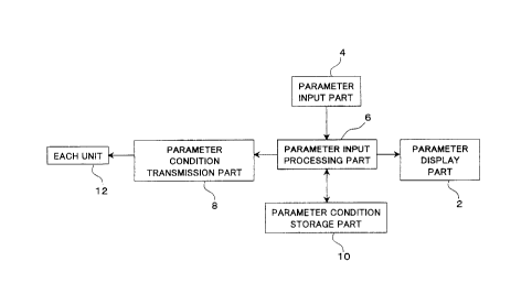
Fig. 1 schei~lical!y shows a system controller for an analyzer
according to ~e present invention. The parameter display part 2 is adapted
to display parameter conditions for controHing each unit The parameter
3 0 display part 2 comp~ ises a single uppe~hie~al ~;h.cal parameter screen
CA 02244309 1998-07-29
displaying only the selected parameter(s) and a number of lowe~hierarchical
parameter screens, which correspond to respective units and display all
parameters for these respective units. These parameter screens are
switched by key operation, to be displayed.
The paramete~input part 4 is adapted to input data of information as
to whether or not each parameter is d;splayed on the uppe~hi~ hical
parameter screen and the parameter conditions thereof.
The parameter condition storage part 10 is adapted to store the data
inputted through the paramete~input part 4.
The parameter condition Lr~n~ lission part 8 transmits the parameter
conditions for each parameter to a corresponding unit 12.
The parameter input processing part 6 transmits the data from the
parameter input part 4 to tne parameter condition storage part 10, and further
transmits the data stored in the pararneter storage part 10 to the parameter
display part 2 and the parameter condition transmission part 8.
Fig. 2 schematically shows an embodiment of the present invention,
which is applied to a high-speed liquid cl~,~n~lograph. The LCD (liquid
crystal display unit) 14 is provided for the displaying of parameter conditions to
control respective units. The LCD 14 sw~tchably displays an upper-
2 0 hierarchical ,~ me~er screen displaying only a selected parameter and
lowe~hiel drci~..cal parameter screens displaying all parameters for respective
units. The keyboard 16 is provided to input parameter conditions and
display/non ~;s,~lay modes on the uppe~hierarchical parameter screen. The
CPU 18 and the ROM 20 process the data inputted from tne keyboard 16.
2 5 The RAM 22 stores the data inputted fi om the keyboard 16 and processed in
the CPU 18 and the ROM 20. The data processed in the CPU 18 and tne
ROM 20 are lr~n~ Led to units such as a pump and a detector tnrough an
interface 24, so tnat the respective units change conditions on the basis of
signals thereof. The signals detected by the detector are processed in the
3 0 CPU 18 and ~e ROM 20, to be thereafter tl~nsl . Iil~ed to an extemal PC
..
CA 02244309 1998-07-29
(personal computer).
Describing the relation between Figs. 1 and 2, the LCD 14 shown in Fig
2 implements the parameter display part 2 shown in Fig. 1, the CPU 18 and tne
ROM 20 implement the parameter input processing part 6, the RAM 22
5 implements the parameter condition storage part 10, and the interface 24
implements the parameter condition l-~nslnission part 8.
Fig. 3A shows an exemplary upper~hierarchical parameter screen (a)
and Fig. 3B shows an exemplary lower-hierarchical parameter screens (b).
The lower-hierarchical parameter screen (b) displays all parameters of each
10 unit The screen (b) in Fig 3B, for example, displays all parameters of a pumpunit. Such a screen (b) is prepared for every unit. On the other hand, the
upper-hierarchical parameter screen (a) collects and displays only the
parameter~s) selected in these lower-hierarchical screens (b).
Fig. 4 is a flow chart showing an operation procedure in the selection
15 or cancellation of parameters displayed on the upper-hierarchical parameter
screen (a). The operation procedure for parameter selection or cancellation
is now described with reference to Figs. 3A, 3B and 4. The following
description is made witn reference to pump parameters.
Parameter screen (a) refers to the uppe~hierarchical parameter
2 0 scr~en (Fig 3(A)) displaying only frequently changing parameters selected bythe user amon~g the parameters of each unit Parameter screen (b3 refers to
the lower-hierarchical parameter screen (Fig. 3(B)) which is present for each
unit to display all parameters changeable in the unit
When selecting a parameter screen from a menu screen, screen (a) is
2 5 displayed. When screen (a) already displays only tne pan~n~ ers to be
displayed, the parameter selection is finished.
If screen (a) displays no parameters to be displayed or parameters not
to be displayed, the user presses the display screen switching key to display
screen (b) of a unit (a pump in this case) including the parameters. The user
3 0 finds out the parameters, to be displayed or erased on screen (a), on screen
CA 02244309 1998-07-29
(b), and moves the cursor to the parameters on screen (b). At this time, the
user presses the function key SEL/DEL on the lower left of screen (b) to
select a display.
Selection marks * are displayed on the left sides of the parameters,
5 which are selected to be displayed on screen (a), on screen (b). When the
user moves the cursor to the parameters and presses the function key
SEL/DEL" again, the selection is canceled, the display on screen (a) is also
canceled and the display of the selection marks * is erased. It is assumed
here that "T. FLOW, ' B. CONC and P. MA)( are selected.
After completing the selection of all necessary parameters on screen
(b), the user presses the display screen-switching key to retum the display to
screen (a). Consequently, only T. FLOW, B. CONC and P. MAX
selected on screen (b) are displayed on the pump parameter display pa~t of
screen (a). Thus, the parameter selection is finished.
Fig 5 is a flow chart showing a parameter set procedure. The
parameter screens (a) and (b) are identical to those in Figs. 3A and 3B. The
parameter set procedure is now described with reference to Fig. 5.
When the user selects a parameter screen from the menu screen,
screen (a) is displayed (Sl ). If there is no chanbng of the parameter value,
2 0 the pardll)eter set procedure is finished (S2).
However, if there is changing of the parameter value, the user
co,lr~n~ Is whether or not the parameter to be changed is present on screen (a)
(S3). The user changes the parameter value if the parameter is present (S4),
and the parameter set procedure is finished if there are no other parameter
2 5 values to be changed (S2).
If there are no parameters to be changed on screen (a), the user
presses the display screen switching key to display screen (b) including the
parameter to be changed (S5), and co"r~ )s whether or not the parameter to
be changed is present on screen (b) (S6). The user changes the parameter
3 0 value if the pa, dn ,eter is present (S7), and he presses the display screen-
CA 02244309 1998-07-29
switching key to retum to screen (a) (S6 ~ S1 ) if no parameter is present If
no other parameters are to be changed, the parameter set procedure is
finished (S2).
In the case of changing the parameter, this can be done by repeating
5 the procedure of S2 ~ S3 ~ S4 if the parameter to be changed is present on
screen (a). however, if the parameter to be changed is not present on screen
(a), this must be done by repeating the procedure of S1 ~ S2 ~ S3 ~ S5 ~
S6 ~ S7 ~ S6 ~ S1 which is more complicated. Therefore, the parameter
to be changed in daily analysis is p~efer~bly displayed on screen (a) in advance.
Although the present invention has been described and illustrated in
detail, it is clearly understood that the same is by way of illustration and
example only, and is not to be taken by way of limitation as the spirit and
scope of the present invention is limited only by the terms of the appended
clalms.