Note: Descriptions are shown in the official language in which they were submitted.
CA 02244463 1998-07-27
FE-02
CHECKING DEVICE FOR PRINTING GROUP
The present invention is directed to a checking device for
the printing unit of printing apparatus, a printing apparatus
provided with a device of this kind, and a met~od rOr installing
a c~ecking device in a printing apparatus.
There are commercially available printing apparatus which
pri~t value marks or the like marks that are s~b~ect to monetary
charges ~nd that are generally of~icially or otherwise
~uthorized. An example is postage metering ~achines or franking
machines by means o~ which postal franking can be imprinted on
letters and packages in a business. The basic construction of
machines of this type is ~nown and described, for example, in EP-
560 716. ~epending on regulations and pract~ces of specific
rcgions, the franking machine as described, for example, in EP- -
390 731 is loaded with ~ranking amounts purchased beforehand at
the post office by credit card or electronic monet~ry transfer.
In normal ope~ation, the franking device then prints the desired
postage or ~ran~ing amount, e.g., o~ an envelope, by means oS its
printing unit and ~imultaneously debits the corresponding
~ranking value to the card or stored credit amount.
~ owever, it is conceivable that the franking machine could
be manipulated in Eiuch a way that its printing unit could print
value marks on shipping items without ~imultaneous or subseguent
debiting. For example, this can be carried out by controlling
CA 02244463 1998-07-27 -
. - 2 -
the prlnting unit through illicitly tap~ing into the usually
unprotected connection llne between the deb~ting electronic~ and
the control Qlectronics of the printing unit. It is also
: conceivable to put the printing un~t in operation by ~eans o~ an
external power supp}y, i.e., a power supply not belong~ng to the
~achine, or by manual driving, e.g., by turning the printing
rollsr when the machi~e is disconnected from the power supply.
Countermeasures ~o~ the ~irst type of misuse are described, for
example, in U,S. Patent 4,253,158 and in EP-0018081. However,
the second and third problems mentioned abovQ have so far not
been solved. Furt~er problems ar~ posed by all of the ~imilar
illicit tampering with pr$nting units in other printing
technology, e.g., by supplying external power ~o the power supply
connection o~ a thermal printer.
one ob~ect of the present invention, therefore, is tO 5O1Ve
these unsolvgd problems. In addition, protection of printing
unitS and apparatus comprising printing units ~gainst illici~ use
i6 to be increased generally. This is intended not only f or new
prlnting units and apparatus, but also for all of the numQrous
dQvices that have already been issue~ and are in use. AB a
r~sult of insufficient security, the period Or use of these older
devices has already been severely restricted by the authorizing
boaies. Therefore, in the time to come, many devices which in
th~ms~lve~ are Stl}i capabie or runctioning for a long time will
have to be removed from use. For ~his reason, the present
invention also h~s the object Or enabling the ~urther use of
CA 02244463 1998-07-27
-- 3
these devices by means of retrofitting in the most efficient and
economical way possible and so as to provide the required
security. A further object of the invention consists in the
complete monitoring and checking of proper use of the contracting
of value marks by the authorized user of the printing unit and/or
apparatus. This provides a guarantee for the authorizing body
and offers complete security for legal credit accounting.
Finally, correspondingly outfitted devices, in particular,
franking machines, are also to be provided. A further goal of
the invention also consists in that value mark dispensing devices
which are based on personal computers with conventional or
special printers and with or without special additional
electronics (see CH-2332/96) are monitored in the manner
mentioned above and protected against misuse.
These objects are met through the technical teachings
indicated in the independent patent claims and in the application
text in its entirety.
on the one hand, the suggested measures enable an autonomous
recording in the checking device of all printing processes and
manipulation in the checking device itself. Due to the fact that
it possesses its own power supply within the protected housing, a
complete service history of the checking device is made. In a
preferred embodiment form, the checking device is connected,
e.g., by means of a noncontacting communications arrangement,
with the controlling and debiting electronics (e.g., a security
card according to US-5 509 117) of the printing apparatus. In a
CA 02244463 1998-07-27
suitable construction, the electronics of the checking device
have their own service history and, in addition, also that of the
controlling and debiting electronics communicating with it, or
vice versa. The authorizing body therefore always has at its
disposal at least one, if not two, possibilities for checking the
printing processes carried out with the device in the course of
its use. In the event of any discrepancy between the service
history of the checking device and that of the apparatus, more
extensive security measures trigger an interruption in operation
either immediately or so as to be controlled according to time or
according to the quantity of printing processes after tampering
has been detected. In a further arrangement, the control
electronics check whether or not the checking device is still
present and/or whether it is functioning as intended. When the
results of the check are negative, the apparatus can be blocked
by the control electronics directly or, as described above, as a
function of time or printing number. If the apparatus offers the
possibility of data transfer, as it is called, (see US-5 509
117), the data files of the checking device are advisably
transferred in addition to the data of the possibly defective
controlling and debiting electronics. In this way it is ensured
that all data relating specifically to franking (including a
complete listing of the franking carried out, possibly with
reference to date and time or only sequentially, the individual
values of the franking, counter states or counter readings,
credit upgrades, tests, manipulation for repair purposes, any
CA 02244463 1998-07-27
-- 5
exchanging of parts or component groups, with or without data
transfer requirement) can always be verified in the apparatus
and, therefore, by the owner of the apparatus and are retained.
This advantage is also retained in apparatus having data transfer
possibilities when the apparatus has to be exchanged for a
replacement apparatus for repair purposes, especially as the
service technician has no access to the security card and its
data contents (see US-5 509 117). In summary, it is noted once
more that the suggested measures offer the authorizing body an
uninterrupted, tamper-proof and accordingly 100-percent secure
monitoring of the important postage data which includes the
entire service history of the apparatus.
Because of the economical checking device and its equally
economical assembly, older apparatus can be retrofitted
efficiently. As a result of this measure, apparatus which in
themselves would still be operational for a long time can be used
for an additional number of years. The consequent economic and
also environmentally relevant and energy-saving advantage is
enormous. Therefore, the claimed retrofitting process also
represents a significant invention with respect to economy among
others.
As was described above by the example of older apparatus,
conventional printing units of a franking machine controlled by a
PC can similarly be provided with a retrofitted checking device.
Of course, the protective scope of patent claims 10 and 11 also
-
CA 02244463 1998-07-27
extends to such retrofitting and to the installation of checking
devices in the PC or other computer printers.
An embodiment example of the invention is described more
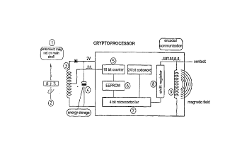
fully hereinafter with reference to the diagram. The drawing 1/1
shows the basic wiring circuit configuration of the checking
device along with a noncontacting data readout variant. Details
and combinations of the electronic and mechanical structures in
the apparatus familiar to the person skilled in the art are
deliberately omitted for the sake of improved clarity insofar as
they do not relate to the construction or operation of the
present device according to the invention. In this respect,
reference is had to the cited patent documents and the apparatus
sold by FRAMA at the time of this patent application.
The checking device has a sensor which responds specifically
to the operation of the existing printing unit. When a rotating
printing shaft or linearly moving printing stamp is provided, the
sensor can operate in a noncontacting manner magnetically,
optically, inductively or based on similar principles. The
signal-generating element, e.g., a magnet 1 in the present case,
is preferably installed in the printing shaft 2 or in the
printing cylinder so as to be invisible from the outside. An
infrared diode or inductive resistor (coil) may also be similarly
installed instead of the magnet. A purely mechanically working,
noncontacting signal transmitter would also be possible.
However, the latter has disadvantages compared to the former
(including easy detectability). A coil 3, phototransistor,
CA 02244463 1998-07-27
-- 7
voltage field sensor or the like elements are used in this case
as a signal receiver, these elements being arranged within the
housing of the checking device or on the surface thereof.
In the case of a thermal printing unit, the sensor can be a
temperature-sensitive measuring element or a measuring element
that detects temperature by way of other effects. In this case,
the heating mechanism of the printing unit acts as a signal
transmitter.
In the case of an ink jet printer, the sensor can be a
microphonic element which responds to sound. In this case, also,
the ink jet itself or the element triggering the ink jet delivers
the signal.
In the case of laser printers, the sensors and signal
transmitters mentioned above are also conceivable.
Further, the following elements are arranged inside the
housing of the checking device: An independent power supply for
the checking device, e.g., a long-life battery 4, a counter 5,
e.g., a nonresettable electric digital counter of known
construction with, for example, 64,000 or 64 million counting
units, and a storage element 6, e.g., an EEPROM. A conventional
microcontroller 7 connected with the counter assigns additional
identification data to the respective counter value, e.g., the
event time and/or event date.
The data from the controller 7 are subsequently transferred
therefrom by means of a shift register 8, for example, in encoded
form, by way of an additional coil 9. The transmission technique
CA 02244463 1998-07-27
shown herein enables a noncontacting data transfer by means of
suitable signal receivers in the security card of the franking
machine. However, for simple applications, data can also be
transferred by means of installed signal lines. Of course, the
data transfer can be controlled by the microcontroller or can be
triggered externally.
The security card makes use of software programs stored
therein to compare the contents of the internal counter 5 of the
checking device with the number of printing processes which it
determines itself in a known manner. If these independently
determined data do not agree or do not fall within an elected
interval, the security card blocks all further printing processes
immediately or, if desired, after a delay with respect to time or
event number.
The microcontroller 7 also checks its own state sequentially
or continuously. By means of suitable known sensors, e.g., a
current-conducting micro-wire, microphone, magnetic field sensor
or the like, the microcontroller 7 detects illicit manipulation
performed on it (attempted disassembly, attempted opening and the
like), including removal from its original position. These data
are stored, also for purposes of the above-described service
history, in a nonvolatile or permanent memory 6 and sent to the
security card via coil 9. This security card stops the printing
unit in the above-described manner as in the case of a
discrepancy in the counter readings or failure to recognize the
checking device.
CA 02244463 1998-07-27
g
Of course, all of the elements or functional groups
described herein can be replaced by others without departing from
the protective scope of the patent claims. It is important only
that the inventive teaching is adhered to, wherein this teaching
consists in that a checking device which is self-sufficiently
powered at least over a time period of days, months or years and
reacts to any impermissible actions upon it, i.e., those
impairing the intended function, delivers its signals, including
the total number of printing processes carried out as detected by
suitable sensors, to suitable controlling and security elements
of the franking machine. For reasons of security only, the exact
construction of the circuit and that of the utilized signal
receiver and signal transmitter cannot be described herein more
fully than has already been done. Several variants will be
touched upon in order to demonstrate the wide boundaries within
which a person skilled in the art can carry out modifications of
the described embodiment form without departing from the
framework of the invention:
- A capacitor which charges by means of the magnetic field
changing during the rotation of the magnet 1 via coil 3 can be
used in place of the battery 4. However, photocells in the
interior of the apparatus which deliver their current to an
accumulator are also possible.
- The checking device can be installed so as to be concealed
in a suitably thick-walled region of the housing of the franking
CA 02244463 1998-07-27
-- 10 --
machine, i.e., its housing is partly identical to the franking
machine housing.
- The printing detection sensor and, e.g., the controller can
be arranged in two different housings and can have separate power
supplies. The data transfer between the two housings can be
carried out in an optional manner, e.g., optoelectronically.
- The checking device can be attached to the franking machine
by riveting, gluing, welding or in a comparable manner. Suitable
sensors, e.g., foil strips, can be provided at or in the
connection point for position verification or recording of
tampering.
- A plurality of counters can be provided in the checking
device, e.g., for the sum total and daily total.
- The checking device must periodically be charged by a test
signal regardless of whether or not the franking machine is being
put to use. If it is not recharged, it will block the franking
machine. By means of this step, the post office can check
whether or not the machine has been used in the contracted
manner.
- When mishandling occurs or attempted fraudulence has been
determined, data transfer is rendered impossible or data transfer
is coupled with an alarm signal which acts immediately or
subsequently.
- Servicing procedures are recorded in memory. They may be
signalized in an optional manner, e.g., by security card signals
CA 02244463 1998-07-27
or special signals which are loaded into the apparatus by an
auxiliary transmitter.
- The checking device can cooperate with additional elements
of the franking machine, e.g., an autonomous locking mechanism
(see CH-2333/96) with the objective of increased security.
The invention is not limited to the embodiment form
described and illustrated in the Figures. Rather, it comprises
all apparatus, equipment and methods in which the teaching of the
claims is realized or suggested.
The claims remain subject to subsequent supplementation
through portions of the description and/or drawing. It is noted
once again that means other than the above-mentioned construction
elements and individual elements can be used provided they
fulfill the same or a similar purpose. All possible combinations
of the individual elements also fall within the scope of
protection.