Language selection

Search

Patent 2244528 Summary

Third-party information liability

Some of the information on this Web page has been provided by external sources. The Government of Canada is not responsible for the accuracy, reliability or currency of the information supplied by external sources. Users wishing to rely upon this information should consult directly with the source of the information. Content provided by external sources is not subject to official languages, privacy and accessibility requirements.

Claims and Abstract availability

Any discrepancies in the text and image of the Claims and Abstract are due to differing posting times. Text of the Claims and Abstract are posted:

  • At the time the application is open to public inspection;
  • At the time of issue of the patent (grant).
(12) Patent: (11) CA 2244528
(54) English Title: LEAKTIGHT FITTING FOR A SHAFT END
(54) French Title: AJUSTEMENT ETANCHE POUR UNE EXTREMITE D'ARBRE
Status: Expired
Bibliographic Data
(51) International Patent Classification (IPC):
  • F16J 15/3228 (2016.01)
  • F02C 7/28 (2006.01)
  • F16J 15/00 (2006.01)
(72) Inventors :
  • LETURCQ, MICHEL MARIE MAURICE (France)
(73) Owners :
  • SOCIETE HISPANO SUIZA (Not Available)
(71) Applicants :
  • SOCIETE HISPANO SUIZA (France)
(74) Agent: LAVERY, DE BILLY, LLP
(74) Associate agent:
(45) Issued: 2007-10-23
(22) Filed Date: 1998-08-04
(41) Open to Public Inspection: 1999-02-13
Examination requested: 2003-06-02
Availability of licence: N/A
(25) Language of filing: English

Patent Cooperation Treaty (PCT): No

(30) Application Priority Data:
Application No. Country/Territory Date
97 10313 France 1997-08-13

Abstracts

English Abstract

The present invention relates to a leaktight seal with a lip capable of gripping a shaft end and fitted behind a cap. When the cap is in place covering the shaft end and closing the housing, it presses on a stop flange of seal and pushes the lip outwards so that the rotation of the shaft end causes no wear to the seal. When the cap is removed, the housing remains open but the lip grips the shaft end and restores the leaktight seal. This fitting is of particular use for shaft ends fitted with a key slot used for manually rotating a rotating machine during the inspection phase of servicing, the shaft end being driven during normal use of the machine.


French Abstract

La présente invention porte sur un joint d'étanchéité à lèvre capable d'agripper l'extrémité d'un arbre et monté derrière un capuchon. Quand le capuchon est en place recouvrant l'extrémité de l'arbre et fermant le boîtier, il appuie sur une bride d'arrêt du joint et pousse la lèvre vers l'extérieur de façon à ce que la rotation de l'extrémité de l'arbre n'entraîne aucune usure de l'arbre. Quand le capuchon est retiré, le boîtier demeure ouvert mais la lèvre agrippe l'extrémité de l'arbre et restaure l'étanchéité du joint. Ce dispositif est particulièrement utile pour les extrémités d'arbre dotées d'un logement de clavette utilisé pour la rotation manuelle d'une machine rotative durant la phase d'inspection de la maintenance, l'extrémité de l'arbre étant entraînée durant l'utilisation normale de la machine.

Claims

Note: Claims are shown in the official language in which they were submitted.


6


CLAIMS


1. Leaktight fitting for a shaft end located behind a movable cap on
an aperture in a shaft end housing, comprising a leaktight seal fastened to
the
housing, located between the housing and the shaft end, said seal comprising
an elastic lip tending to rest on the shaft end, said cap comprising a pusher
component lying around the shaft end and pushing the elastic lip of the shaft
end when the cap is placed on the aperture.


2. Leaktight fitting of claim 1, wherein said seal is substantially flat
in a rest state.


3. Leaktight fitting of claim 1, wherein said seal comprises a
retaining strip that is set into the housing and a stop flange hinged at the
retaining strip and directed towards the cap, the lip being conical and
reducing
remote from the cap and connected to the stop flange.


4. Leaktight fitting of claim 1, wherein said lip is made of elastic
material.


5. Leaktight fitting of claim 4, wherein said lip is made of elastomer.

6. Leaktight fitting of claim 4, wherein said lip is made of PTFE.


7. Leaktight fitting of claim 4, wherein said lip is reinforced by
means of a metallic spring.


Description

Note: Descriptions are shown in the official language in which they were submitted.


CA 02244528 1998-08-04
1

LEARTIGHT FITTING FOR A SHAFT END
DESCRIPTION
The present invention relates to a leaktight
fitting for a shaft end, particularly for a shaft end
located in a housing and protected from the outside by
a cap that can be removed when required.
The advantages of this type of shaft end may be
understood by studying figure 1 which shows a gas
turbine. Working from front to back along an annular
gas circulation channel 1, are fitted a blower 2, a low
pressure compressor 3, a high pressure compressor 4, a
combustion chamber 5, a high pressure turbine 6 and a
low pressure turbine 7. The channel 1 contains fixed,
circular blade stages constructed as part of a housing
8 that delimits the outside of the channel and rotating
blades connected to a rotor 9 that delimit the inside
of the channel. The rotor 9 also comprises a line of
low pressure shafts 10 that interconnect the blower 2,
the low pressure compressor 3 and the low pressure
turbine 7, as well as a line of high pressure shafts 11
that interconnect the high pressure compressor 4 and
the high pressure turbine 6. The lines of shafts 10 and
11 are coaxial and the line of high pressure shafts 11
surrounds the line of low pressure shafts 10. The line
of shafts ends at the front in a conical gear wheel
that co-ordinates with a first conical gear wheel of a
transmission shaft 12 radially positioned to form an
angled gear 13. Another angled gear 14 is formed at the
opposite end of transmission shaft 12 between another
conical gear wheel mounted on the shaft and a final
conical gear wheel located at the rear end of shaft end
15. Shaft end 15 lies parallel to the shaft lines 10
and 11 and next to the low pressure compressor 3 and
the blower 2. Its forward end finishes behind a plane
SP 14036 JCI


CA 02244528 1998-08-04
2

surface 16 of housing 8, opposite an aperture 17 that
is closed by a cap 18 gripped by an elastic ring 19
clamped between the cap and aperture 17. This ring 19
also ensures the leaktightness of aperture 17.
The shaft end 15 allows individual inspection of
the blades connected to the line of high pressure
shafts 11 and particularly the blades of the high
pressure compressor 4. It is known that blades are
relatively fragile structures that can be easily
damaged, for example when a foreign body is introduced
into the gas turbine. The method for inspecting the
blades consists firstly in disassembling the gas
turbine and opening a window of housing 8 facing one of
the stages of the rotating blades to be inspected,
usually the first of compressor 4, and then rotating
the line of high pressure shafts 11 in order that all
the blades of the stage pass successively in front of
the window. Movement is brought about using a key (not
shown, but of standard design) which is inserted into
an opening located at the front of shaft end 15. The
key is inserted through slot 17 once the cap 18 is
removed and can be operated by hand or by a dedicated
device. A drawback, however, of this construction is
that the operator may forget to replace cap 18,
resulting in a large quantity of the oil contained in
housing 8 draining from aperture 17 as soon as
operation of the gas turbine is resumed, thus rapidly
emptying the housing 8. Despite seal 19, cap 18 may
also be accidentally dropped.
The present invention was designed to combat this
risk. It consists in adding a leaktight seal between
shaft end 15 and housing 8 in order to maintain
leaktightness even when cap 18 is removed.
It should, however, be pointed out that the shaft
end 15 rotates with the line of high pressure shafts 11
SP 14036 JCI


CA 02244528 1998-08-04
3

while the gas turbine is in use and is likely to cause
rapid wear of the recently-added joint. The major
contribution of the invention to the art therefore
consists of the special construction of the added
leaktight seal and of the cap designed to overcome this
difficulty.
In its commonest form the invention therefore
relates to a leaktight fitting for a shaft end fitted
behind a movable cap on an aperture in the housing of
the shaft end, characterized by the fact that it
comprises a leaktight seal fastened to the housing,
located between the housing and the shaft end and
comprising an elastic lip tending to rest on the shaft
end, and by the fact that the cap comprises a pusher
component lying around the shaft end and pushing the
elastic lip of the shaft end when the cap is placed on
the aperture.
The special characteristics, aims and advantages
of the invention will be better understood from the
description of the attached figures where:
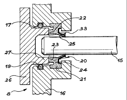
- figure 1 (described above) shows a gas turbine
fitted with a shaft end to which the invention may be
fitted;
- figure 2 shows a first embodiment of the
invention;
- figure 3 shows a second embodiment of the
invention.
Seal 20 added with the invention and shown in
figure 2 comprises a retaining strip 21 that is set
into a groove 22 in the housing 8, a stop flange 23
connected to the retaining strip 21 by necking 24, and
a conical lip 25 whose diameter reduces towards the
inside of the housing and which is connected to the
stop flange 23. The narrowest edge of lip 25 (i.e.
facing the stop flange 23) rubs against shaft end 15
SP 14036 JCI


CA 02244528 1998-08-04
4

when the cap is absent. The housing 8 thus remains
satisfactorily leaktight even without the cap.
The inner surface of cap 26 modified according to
the invention comprises a cylindrical pusher component
27 that encloses the shaft end 15 and presses against
stop flange 23. When the cap 26 presses against the
surface 16 of the housing, the pusher 27 forces the
stop flange 23 towards the inside of the housing 8 and
since necking 24 acts as a hinge, the stop flange 23
and the lip 25 are subjected to a slight rotation that
causes lip 25 to open, thereby acquiring a slightly
larger diameter and causing its free end to distort and
detach from the shaft end 15 as shown by the dotted
lines. The machine may thus be operated without the
rotating shaft end 15 rubbing against lip 25 that is
only subject to wear if the cap 26 has been left off or
accidentally dropped.
When compressed, the 0-ring 19 also acts as a
standard-type seal between the plane surface 16 of
housing 8 and cap 26.
Figure 3 shows another embodiment. The seal, here
numbered 30, is simpler than seal 20 above. It is, in
fact, a disk whose center has been cut out; its flat
outer section 31 enables it to be set it into housing 8
so that its lower part can bend inwards into the
housing, once again acting as a lip 32 whose edge is in
contact with shaft end 15 when at rest. As before, the
pusher 27 of cap 26 presses on lip 32 when it is
installed, opening it and freeing it from shaft end 15,
again as shown by dotted lines. Iri contrast with the
previous embodiment in which seal 20 was located
towards the outside of plane surface 16, this seal is
located on the inside.
The seal 20 or 30 must be constructed either of
elastomer or a material that is both elastic and
SP 14036 JCI


CA 02244528 1998-08-04

flexible enough to be subjected to adequate temporary
deflection. The material used may also be, for example,
PTFE.
Once specialists in the trade have understood the
5 operating principle behind the invention, they will
easily find other suitable embodiments. We would simply
point out that lip 25 or 32 may be strengthened by
means of a metallic core to stiffen it without reducing
its elasticity. This type of core is shown in figures 2
and 3 and numbered 33. In this particular embodiment, a
strip is used to line the lip 32, which is turned
inwards into the housing. As is well known in the art,
this type of metallic spring may be replaced by others.
SP 14036 JCI

Representative Drawing
A single figure which represents the drawing illustrating the invention.
Administrative Status

For a clearer understanding of the status of the application/patent presented on this page, the site Disclaimer , as well as the definitions for Patent , Administrative Status , Maintenance Fee  and Payment History  should be consulted.

Administrative Status

Title Date
Forecasted Issue Date 2007-10-23
(22) Filed 1998-08-04
(41) Open to Public Inspection 1999-02-13
Examination Requested 2003-06-02
(45) Issued 2007-10-23
Expired 2018-08-06

Abandonment History

There is no abandonment history.

Payment History

Fee Type Anniversary Year Due Date Amount Paid Paid Date
Application Fee $300.00 1998-08-04
Registration of a document - section 124 $100.00 1998-10-08
Maintenance Fee - Application - New Act 2 2000-08-04 $100.00 2000-07-28
Maintenance Fee - Application - New Act 3 2001-08-06 $100.00 2001-07-18
Maintenance Fee - Application - New Act 4 2002-08-05 $100.00 2002-07-31
Request for Examination $400.00 2003-06-02
Maintenance Fee - Application - New Act 5 2003-08-04 $150.00 2003-07-28
Maintenance Fee - Application - New Act 6 2004-08-04 $200.00 2004-07-21
Maintenance Fee - Application - New Act 7 2005-08-04 $200.00 2005-07-28
Maintenance Fee - Application - New Act 8 2006-08-04 $200.00 2006-07-25
Final Fee $300.00 2007-07-11
Maintenance Fee - Application - New Act 9 2007-08-06 $200.00 2007-07-25
Maintenance Fee - Patent - New Act 10 2008-08-04 $250.00 2008-07-28
Maintenance Fee - Patent - New Act 11 2009-08-04 $250.00 2009-07-27
Maintenance Fee - Patent - New Act 12 2010-08-04 $250.00 2010-07-26
Maintenance Fee - Patent - New Act 13 2011-08-04 $250.00 2011-07-25
Maintenance Fee - Patent - New Act 14 2012-08-06 $250.00 2012-07-23
Maintenance Fee - Patent - New Act 15 2013-08-05 $450.00 2013-07-24
Maintenance Fee - Patent - New Act 16 2014-08-04 $450.00 2014-07-24
Maintenance Fee - Patent - New Act 17 2015-08-04 $450.00 2015-07-24
Maintenance Fee - Patent - New Act 18 2016-08-04 $450.00 2016-07-20
Maintenance Fee - Patent - New Act 19 2017-08-04 $450.00 2017-07-20
Owners on Record

Note: Records showing the ownership history in alphabetical order.

Current Owners on Record
SOCIETE HISPANO SUIZA
Past Owners on Record
LETURCQ, MICHEL MARIE MAURICE
Past Owners that do not appear in the "Owners on Record" listing will appear in other documentation within the application.
Documents

To view selected files, please enter reCAPTCHA code :


To view images, click a link in the Document Description column. To download the documents, select one or more checkboxes in the first column and then click the "Download Selected in PDF format (Zip Archive)" or the "Download Selected as Single PDF" button.

List of published and non-published patent-specific documents on the CPD .

If you have any difficulty accessing content, you can call the Client Service Centre at 1-866-997-1936 or send them an e-mail at CIPO Client Service Centre.


Document
Description 
Date
(yyyy-mm-dd) 
Number of pages   Size of Image (KB) 
Cover Page 1999-03-03 1 52
Abstract 1998-08-04 1 23
Representative Drawing 1999-03-03 1 11
Description 1998-08-04 5 209
Claims 1998-08-04 1 38
Drawings 1998-08-04 2 55
Claims 2006-09-22 1 26
Abstract 2006-09-22 1 17
Representative Drawing 2007-09-24 1 16
Cover Page 2007-09-24 1 44
Fees 2000-07-28 1 39
Prosecution-Amendment 2006-09-22 6 144
Assignment 1998-10-08 2 75
Correspondence 1998-10-06 1 30
Assignment 1998-08-04 3 100
Prosecution-Amendment 2003-06-02 1 21
Fees 2003-07-28 1 36
Prosecution-Amendment 2003-09-09 1 31
Fees 2007-07-25 1 45
Fees 2002-07-31 1 45
Fees 2005-07-28 1 33
Fees 2001-07-18 1 39
Fees 2004-07-21 1 35
Prosecution-Amendment 2006-03-27 2 48
Fees 2006-07-25 1 43
Correspondence 2007-07-11 1 32