Note: Descriptions are shown in the official language in which they were submitted.
CA 02244~48 1998-08-0~
METHOD AND APPARATUS FOR HYDROFORMING METALLIC TUBE
BACKGROUND OF THE INVENTION
1. Field of the Invention
The present invention relates to a method and an
apparatus for hydroforming a metallic tube.
2. Description of the Related Art
Metallic tube hydroforming comprises the steps of
introducing a hydraulic fluid into a metallic tube serving
as a material tube (hereinafter, referred to merely as a
metallic tube) and applying an axial force to the tube ends,
to thereby form the metallic tube through combined use of
hydraulic pressure and the axial force. The hydroforming
process provides tubular parts having a variety of cross-
sectional profiles.
Figs. 7(al), 7(a2), 7(bl), 7(b2), 7(cl), and 7(c2)
show a metallic tube and products. Fig. 7(al) is a side
view showing a metallic tube, and Fig. 7(a2) is a front view
showing the metallic tube. Figs. 7(bl) and 7(cl) are side
views of products obtained through tube hydroforming, and
Figs. 7(b2) and 7(c2) are front views of the products.
Each of the products includes an expanded portion 2a
(3a) having a rectangular cross section and end portions 2b
(3b) having the same outer diameter as a diameter Do of a
metallic tube 1. Figs. 7(bl) and 7(b2) show a product 2 in
which side lengths D1 and D2 of the expanded portion 2a are
larger than the tube diameter Do.
CA 02244~48 1998-08-0~
Figs. 7(cl) and 7(c2) show a product 3 in which at
least one (in this case, D1) of side lengths Dl and D2 of the
expanded portion 3a is smaller than the tube diameter Do.
Overall lengths L1 and L2 of the products 2 and 3,
respectively, are shorter than the length Lo. of tube 1
First will be described a conventional hydroforming
apparatus used for obtaining the product 2.
Figs. 8(a) and 8(b) show a die portion of the
conventional hydroforming apparatus. Fig. 8(a) is a
longitudinal sectional view showing the die portion. Fig.
8(b) is a sectional view taken along the line C-C of Fig.
8(a)-
The die is composed of a lower die 4 and an upper die5. The lower die 4 is attached to a bolster 10 of an
unillustrated press unit. The bolster 10 is located at a
lower portion of the press unit. The upper die 5 is
attached to a ram head 11 of the press unit. The ram head
11 is located at an upper portion of the press unit. The
ram head 11 is moved vertically by means of an unillustrated
hydraulic cylinder so as to press the upper die 5 against
the lower die 4 with a predetermined force. Die cavities 4a,
5a and a tube-holding groove 4b,5b for containing a metallic
tube therein are formed in the upper and lower die 4,5.
When the upper and lower dies 5 and 4 are closed each other,
a space defined ba the die cavities 4a and 5a is used for
forming the expanded portion 2a of a product. The contour
of the die cavities is identical to the external contour of
CA 02244~48 1998-08-0~
the expanded portion 2a of a product. When the upper and
lower dies 5 and 4 are closed each other, a space defined
by the die cavities 4a and 5a is used for forming the
expanded portion 2a of a product. The contour of the die
cavities is identical to the external contour of the
expanded portion 2a of a product. When the upper and lower
dies 5 and 4 are closed each other,the diameter of the space
defined by the tube-holding grooves 4b and 5b is identical
to the outer diameter Do of the metallic tube 1. Left- and
right-hand sealing-punch 6 and 7 are attached to
unillustrated corresponding horizontal press units. The
left- and right-hand sealing-punch 6 and 7 advance toward or
retreat from the left- and right-hand tube-holding grooves
4b and 5b, respectively.
Next will be described a hydroforming process for
obtaining the product 2 through use of the above-mentioned
conventional hydroforming apparatus.
Figs. 9(al), 9(a2), 9(bl), 9(b2), 9(c), and 9(d)
illustrate a conventional hydroforming process. Fig. 9(al)
is a longitudinal sectional view showing a metallic tube set
in the upper and lower dies. Fig. 9(a2) is a sectional view
taken along the line C-C of Fig. 9(al). Fig. 9(bl) is a
longitudinal sectional view showing a final state of
hydroforming. Fig. 9(b2) is a sectional view taken along
the line C-C of Fig. 9(bl). Fig. 9(c) is an enlarged view
showing the encircled portion a of Fig. 9(b2). Fig. 9(d) is
a perspective view showing a product ruptured during
CA 02244~48 1998-08-0
hydroforming.
As shown in Figs. 9(al) and 9(a2), first, the
metallic tube 1 is set in the tube-holding grooves 4b formed
in both end portions of the lower die 4. The ram head 11 is
lowered so as to press the upper die 5 against the lower die
4. The sealing punches 6 and 7 are advanced from their
respective sides so that head portions 6a and 7a of the
sealing punches 6 and 7, respectlvely, are tightly inserted
into both end portions of the metallic tube 1, thereby
the tube ends are sealed during hydroforming. Next, while a
hydraulic fluid 8 is introduced into the metallic tube 1 by
means of an unillustrated pump through a path 6b extending
through the left-hand sealing punch 6, air inside the
metallic tube 1 is ejected through a path 7b extending
through the right-hand sealing punch 7. An unillustrated
valve located on the extension of the path 7b is closed
after the interior of the metallic tube 1 is
filled with the hydraulic fluid 8.
An example of the hydraulic fluid 8 is an emulsion
prepared by dispersing a fat-and-oil component in water in
an amount of several percent so as to produce a rust-
preventive effect. The pressure of the hydraulic fluid 8
contained in the metallic tube 1 is increased advancing the
sealing-punch 6 and 7 to press the metallic tube axially.
Thus, the material of the metallic tube 1 is expanded within
the die cavities 4a and 5a to form the product 2 as shown in
Figs.9(bl)and 9(b2).
CA 02244~48 1998-08-0~
The upper and lower dies 5 and 4 are pressed against
each other during the hydroforming in order to prevent the
upper die 5 from being pressed upward off the lower die 4
when the metallic tube 1 is expanded through the application
of fluid pressure and axial force. Axial pressing is
performed in order to feed the material of the metallic tube
1 located in the tube-holding grooves 4b and 5b into the die
cavities 4a and 5a, to thereby minimize the wall thinning of
an expanded portion of the product 2.
Subsequently, the internal fluid pressure of the
product 2 is reduced to atmospheric pressure. Then, the
upper die 5 is moved upward, and the sealing punches 6 and 7
are retreated, thereby draining the hydraulic fluid 8 from
inside the product 2. The product 2 is ejected from the
lower die 4.
Next will be described a conventional hydroforming
process for obtaining the product 3. Figs. lO(al), lO(a2),
lO(bl), and lO(b2) illustrate conventional dies used for
obtaining the product 3 through hydroforming. Fig. lO(al)
is a longitudinal sectional view of a set of lower die 14
and upper die 15. Fig. lO(a2) is a sectional view taken
along the line C-C of Fig. lO(al). Fig. lO(bl) is a
longitudinal sectional view of an another set of lower die
24 and upper die 25. Fig. lO(b2) is a sectional view taken
along the line C-C of Fig. lO(bl).
In Figs. lO(al) and lO(a2), the rectangular cross
section of a space defined by die cavities 14a and 15a of a
CA 02244~48 1998-08-0~
lower die 14 and an upper die 15, respectively, is profiled
such that a vertical side length D1 is shorter than a
horizontal side length D2. In Figs. lO(bl) and lO(b2), the
rectangular cross section of a space defined by die cavities
24a and 25a of a lower die 24 and an upper die 25,
respectively, is profiled such that a horizontal side length
D1 is shorter than a vertical side length D2-
In hydroforming with either the die shown in Fig.lO(al) or the die shown in Fig. lO(bl), a round metallic
tube can not be used, as will be described later.
In the case of the die shown in Fig. lO(al), the
round tube is set on the die cavity 14a of the lower die 14,
not on the tube holding groove 14b. When the upper die 15 is
lowered, the tube will be crushed between the die cavities
14a and 15a.
Figs. ll(a) and ll(b) are sectional views showing
deformed states of the metallic tube crushed between the
lower die 14 and the upper die 15. Fig. ll(a) shows a
deformed state of the metallic tube within the die cavities,
and Fig. ll(b) shows a deformed state of the metallic tube
within the tube-holding grooves.
As shown in Fig. ll(a), when the upper die 15 is
lowered while a metallic tube 16 is set in the die cavity,
the tube 16 is deformed within the die cavity into a cocoon
shape with side-wall bucklings 17. This also causes
generation of bucklings 18 on portions of the tube 16 within
the tube-holding grooves near the die cavities.
CA 02244~48 1998-08-0~
When these bucklings are clamped between the upper
and lower dies 15 and 14, a product and the dies 15 and 14
must be damaged.
In order to avoid the occurrence of the bucklings,
the round metallic tube must be preformed into a shape which
can be inserted within the die cavities and the tube holding
grooves.
Also, in the case of the die shown in Fig. lO(bl), a
round metallic tube must be preformedi otherwise, the die
cavities 24a and 25a cannot contain the metallic tube.
Figs. 12(al), 12(a2), 12(bl), and 12(b2) are views
illustrating the above-mentioned preforming process. Fig.
12(al) is a longitudinal sectional view showing a state in
which a round metallic tube 1 is set in a flattening die 30
while plugs 32 are inserted into both ends of the tube. Fig.
12(a2) is a sectional view taken along the line C-C of Fig.
12(al). Fig. 12(bl) is a longitudinal sectional view
showing a state in which a punch 31 is lowered from above
with an unillustrated press unit to thereby flatten the
round metallic tube 1. Fig. 12(b2) is a sectional view
taken along the line C-C of Fig. 12(bl).
As shown in Fig. 12(al), a die cavity width D2' of
the die 30 is made slightly smaller than the width D2 of the
die cavities 14a and 15a shown in Figs. lO(a2) and lO(b2).
The plugs 32 are used for prevent deformation of the tube
ends which will be held in the tube-holding grooves 14b and
15b of the dies 14 and 15, respectively. A plug head
CA 02244~48 1998-08-0~
portion 32a has substantially the same diameter as an inside
diameter of the tube. The plug 32 is positioned by
contacting a flange 32b to a tube end.
As shown in Fig. 12(bl), a punch 31 is lowered from
above with an unillustrated press unit so as to flatten the
metallic tube 1 to a height D1', yielding a locally
flattened tube 33. The height D1' is made slightly smaller
than the die cavity width D1 shown in Figs. lO(a2) and (b2).
The cross section of a flattened portion 33a of the
flattened tube 33 becomes a cocoon shape. However, die
walls 30a prevent the occurrence of the bachklings 17 as
shown in Fig.ll(a). The plugs 32 also prevent generation of
the bucklings 18 as shown in Fig.ll((b).
The flattened metallic tube 33 is set in the dies 14
and 15 of Fig. lO(al) or in the dies 24 and 25 of Fig.
lO(bl) and undergoes hydroforming.
Figs. 13(al), 13(a2), 13(bl), and 13(b2) are
sectional views illustrating a tube hydroforming process
conducted through use of the dies 14 and 15 of Fig. lO(al).
Fig. 13(al) is a longitudinal sectional view showing the
flattened metallic tube 33 set in the dies 14 and 15. Fig.
13(a2) is a sectional view taken along the line C-C of Fig.
13(al). Fig. 13(bl) is a longitudinal sectional view
showing a state after the completion of hydroforming the
flattened metallic tube 33. Fig. 13(b2) is a sectional view
taken along the line C-C of Fig. 13(bl). As shown in Fig.
13(al), the flattened metallic tube 33 is set in the die
CA 02244~48 1998-08-0~
cavity 14a and in the tube-holding grooves 14b of the lower
die 14. The upper die 15 is lowered and pressed against the
lower die 14 with a predetermined force, and the sealing
punches 6 and 7 are advanced from their respective sides so
as to insert the punch head portions 6a and 7a into the end
portions of the flattened metallic tube 33, thereby sealing
the punches 6 and 7 against corresponding tube ends. The
flattened metallic tube 33 is filled with the hydraulic
fluid 8. The pressure of the hydraulic fluid 8 is gradually
increased so as to expand the flattened portion 33a having a
cocoon-shaped cross section within the die cavities 14a and
15a, yielding a product formed along the die profile as
shown in Figs. 13(bl) and 13(b2).
Two problems are involved in the conventional
hydroforming process for obtaining the product 2 or the like
described previously with reference to Figs. 9(al), 9(a2),
9(bl), 9(b2), 9(c), and 9(d).
A first problem is wall thinning which occurs at four
corner portions of a cross section of the expanded portion
2a as encircled in Fig. 9(b2). As the ratio of a
circumferential length S2 of the expanded portion 2a of a
product 2 to a circumferential length SO of a metallic tube,
S2/SO, increases or as a radius r of a corner portion as
shown in the enlarged view of Fig. 9(c) decreases, the
degree of wall thinning of a corner portion increases.
Accordingly, a product may fail to obtain required wall
thickness, or excessive wall thinning may cause a rupture 70
CA 02244~48 1998-08-0~
at a corner portion as shown in Fig. 9(d). At a required
corner radius smaller than a critical value, the
conventional hydroforming process may be inapplicable
especially to a tube material having a relatively high
strength, since the ductility of such material is poor.
Through feed of a tube material in tube-holding
grooves into a die cavity by axial pressing with the sealing
punches 6 and 7, wall thinning at corner portions can be
suppressed to some degree. However, when a length L of the
expanded portion 2a of a product is relatively long, the
effect of axial pressing does not reach an axially central
section of the expanded portion 2a. Thus, a wall thinning
problem at corner portions still exists.
According to an experiment conducted by the inventors
of the present invention when, for example, a carbon steel
tube having a 40 kgf/mm2-class tensile strength is
hydroformed into a product whose expanded portion 2a has a
length L four times a tube diameter Do and a square cross
section with S2/SO=1.25 (S2: circumferential length of the
expanded portion 2a; SO: circumferential length of the tube),
the corner radius r cannot be made less than or equal to 5
times a wall thickness t (see Fig. 9(c)).
The degree of wall thinning at a corner portion is
larger than that at a flat side portion. This is because
during hydroforming expansion an increase in the diameter of
a metallic tube is maximized in a diagonal corner-to-corner
direction. Flat side portions of a product come into
CA 02244~48 1998-08-0~
contact with the walls of the die cavities 14a and 15a at a
relatively early stage of hydroforming. Thus, the
extensional deformation of the flat side portions in a
circumferential direction is suppressed by the friction
between the flat side portions and the die cavity walls.
This promotes the extensional deformation of corner portions
in a circumferential direction.
A second problem is that in hydroforming there must
be a relatively high pressure of the hydraulic fluid 8. In
the conventional hydroforming process as described
previously with reference to Figs. 9(al), 9(a2), 9(bl),
9(b2), 9(c) and 9(d), an internal pressure p must be applied
to a metallic tube in order to form a corner portion with a
radius r as shown in Fig. 9(c). The required internal
pressure p can be estimated by the following equation.
p = (t x ~)/r
where t is the wall thickness of a tube material, and ~ is
the strength of a tube material.
For example, with t = 3 mm, ~ = 50 kgf/mm2, and r =
15 mm, p is calculated as 10 kgf/mm2, i.e., a high pressure
of 1,000 atm is required for hydroforming. As the pressure
of the hydraulic fluid 8 increases, a pressure generator
becomes further large-scaled, and a larger force is required
for pressing upper and lower dies each other. Accordingly,
since die strength must be increased, a hydroforming
apparatus becomes expensive, resulting in an increase in
hydroforming cost.
CA 02244~48 1998-08-0~
Also, two problems are involved in the conventional
hydroforming process for obtaining the product 3 or the like
described previously with reference to Figs. 13(al), 13(a2),
13(bl), and 13(b2).
A first problem is the wall thinning of the expanded
portion 3a of the product 3; particularly, wall thinning
which occurs at corner portions of a cross section of the
expanded portion 3a. In hydroforming as illustrated in Figs.
13(al), 13(a2), 13(bl), and 13(b2), resistance which arises
when a tube material passes through stepped portions 14c and
15c of the dies 14 and 15, respectively, hinders smooth
pushing of the tube material in the tube-holding grooves 14b
and 15b into the die cavities 14a and 15a. As a result, the
degree of wall thinning at corner portions becomes rather
large even when a length L of the expanded portion 3a is
relatively short.
A second problem is a shape defect of a rectangular
sectional profile as shown in Fig. 13(b2). This problem
derives from a metallic tube to be hydroformed with a cocoon
shape as shown in Fig. 13(a2).
Figs. 14(a) to 14(c) illustrate generation of the
shape defect. Fig. 14(a) is a sectional view showing an
initial stage of hydroforming. Fig. 14(b) is a sectional
view showing an intermediate stage of hydroforming. Fig.
14(c) is a sectional view showing a final stage of
hydroforming.
As shown in Fig. 14(a), in an initial stage of
CA 02244~48 1998-08-0~
hydroforming, the pressure of the hydraulic fluid 8 causes
convex portions 35 of the cocoon shape to come into contact
with the walls of the die cavities 14a and 15a.
Subsequently, as the fluid pressure increases, the depth of
concave portions 34 decreases gradually. As shown in Fig.
14(b), area of the zones 36 in contact with the die cavity
walls gradually increases with the increase of the fluid
pressure. Due to friction of between the contact zones 36
and the die cavity walls, the concave portions 34 are no
longer deformed. While a tube material of corner portions
37 is extending in a circumferential direction, a corner
radius r gradually becomes smaller. Since a circumferential
material length of the concave portion 34 is excessive, the
concave portions 34 cannot be brought into contact with the
die cavity walls even when the fluid pressure is increased.
As a result, as shown in Fig. 14(c), the concave portions 34
remain in a product. The above-mentioned problems are also
involved in hydroforming through use of the die shown in Fig.
10(b).
SUMMARY OF THE INVENTION
An object of the present invention is to provide a
method and an apparatus for hydroforming a metallic tube
characterized in that no high fluid pressure is required and
a product is free from both wall thinning at its corner
portions and a shape defect.
The inventors of the present invention conducted
CA 02244~48 1998-08-0~
various experiments and intensive studies and found that the
above-mentioned problems can be solved through employment of
hydroforming consisting of primary hydroforming and
secondary hydroforming.
Specifically, in primary hydroforming, a metallic
tube is formed such that a circumferential length of an
expanded portion of the primary-hydroformed tube as measured
at a wall center region of the expanded portion becomes
equal to or slightly shorter than a circumferential length
of an expanded portion of a product as measured at a wall
center region of the expanded portion. In secondary
hydroforming, the outer surface of the expanded portion
formed through primary hydroforming is mechanically pressed
so as to finlsh the cross-sectional profile of the expanded
portion into that of an expanded portion of a product.
Based on the above findings, the present invention
was accomplished. The gist of the present invention is as
follows.
(1) A method for hydroforming a metallic tube in
order to form an expanded portion having an arbitrary cross-
sectional profile through application of a fluid pressure
into the interior of the metallic tube contained in a pair
of upper and lower dies, said method comprising the steps of
primary hydroforming and secondary hydroforming, wherein in
the primary hydroforming step, the metallic tube is formed
such that a circumferential length of an expanded portion of
the primary-hydroformed tube becomes substantially equal to
14
CA 02244~48 1998-08-0~
or slightly shorter than the circumferential length of an
expanded portion of a product and in the secondary
hydroforming step, the expanded portion formed through
primary hydroforming is pressed by one movable pad at least
incorporated within the dies so as to form the cross-
sectional profile of the expanded portion into that of the
expanded portion of the product, and said primary
hydroforming and secondary hydroforming are continuously
performed within the dies.
(2) A method for hydroforming a metallic tube in
order to form an expanded portion having an arbitrary cross-
sectional profile through application of a fluid pressure
into the interior of the metallic tube contained in a pair
of upper and lower dies, said method comprising the steps
of: placing in the dies the metallic tube that has a
circumferential length substantially equal to or slightly
shorter than a circumferential length of an expanded portion
of a product; and pressing the metallic tube by means of one
movable pad at least incorporated within the dies, so as to
form the cross-sectional profile of the metallic tube into
that of the expanded portion of the product.
(3) An apparatus for hydroforming a metallic tube in
order to form an expanded portion having an arbitrary cross-
sectional profile through application of a fluid pressure
into the interior of the metallic tube contained between a
lower die attached to a bolster located at a lower portion
of the apparatus and an upper die attached to a ram head
CA 02244~48 1998-08-0~
located at an upper portion of the apparatus, wherein the
apparatus comprises one movable pad at least incorporated
within the dies, and pressure units contained in the bolster
and ram head for pressing the pads.
(4) A tubular part obtained through a hydroforming
process for a metallic tube by application of a fluid
pressure into the interior of the metallic tube contained in
a die, said hydroformation process comprising the steps of
primary hydroforming and secondary hydroforming, wherein in
the primary hydroforming step, the metallic tube is formed
such that a circumferential length of an expanded portion of
the primary-hydroformed tube becomes substantially equal to
or slightly shorter than a circumferential length of an
expanded portion of a product, and in the secondary
hydroforming step, the expanded portion formed through
primary hydroforming is pressed so as to form the cross-
sectional profile of the expanded portion into that of the
expanded portion of the product.
(5) A tubular part obtained through a hydroforming
process comprising the steps of; placing into dies a
metallic tube that has a circumferential length ubstantially
equal to or slightly shorter than a circumferential length
of an expanded portion of a product;and applying a fluid
pressure into the interior of the metallic tube; and
pressing the metallic tube by means of one movable pad at
least incorporated within the die so as to form the cross-
sectional profile of the metallic tube into that of the
16
CA 02244~48 1998-08-0
expanded portion of the product.
BRIEF DESCRIPTION OF THE DRAWINGS
Fig. l(a) is a longitudinal sectional view showing an
embodiment of a hydroforming apparatus of the present
invention;
Fig. l(b) is a sectional view taken along the line C-
C of Fig. l(a)i
Fig. 2(al) is a longitudinal sectional view showing a
state of a metallic tube being set in a die portion of the
apparatus of Fig. l(a), illustrating a first embodiment of a
hydroforming method of the present invention;
Fig. 2(a2) is a sectional view taken along the C-C
line of Fig. 2(al);
Fig. 2(bl) is a longitudinal sectional view showing a
state of the metallic tube being primary-hydroformed,
illustrating the first embodiment;
Fig. 2(b2) is a sectional view taken along the C-C
line of Fig. 2(bl);
Fig. 2(cl) is a longitudinal sectional view showing a
state of the metallic tube being secondary-hydroformed,
illustrating the first embodiment;
Fig. 2(c2) is a sectional view taken along the C-C
line of Fig. 2(cl);
Fig. 3(al) is a longitudinal sectional view showing a
state of a metallic tube being set in a die portion of the
CA 02244~48 1998-08-0~
apparatus of Fig. l(a), illustrating a second embodiment of
a hydroforming method of the present invention;
Fig. 3(a2) is a sectional view taken along the C-C
line of Fig. 3(al);
Fig. 3(bl) is a longitudinal sectional view showing a
state of the metallic tube being primary-hydroformed,
illustrating the second embodiment;
Fig. 3(b2) is a sectional view taken along the C-C
line of Fig. 3(bl);
Fig. 3(cl) is a longitudinal sectional view showing a
state of the metallic tube being secondary-hydroformed,
illustrating the second embodiment;
Fig. 3(c2) is a sectional view taken along the C-C
line of Fig. 3(cl);
Fig. 4(a) is a sectional view showing an example
cross section of an expanded portion of a hydroformed
product;
Fig. 4(b) is a sectional view showing another example
cross section of an expanded portion of a hydroformed
product;
Fig. 4(c) is a sectional view showing still another
example cross section of an expanded portion of a
hydroformed product;
Fig. 5(a) is a plan view showing a bent hydroformed
product having a plurality of expanded portions formed in a
longitudinal direction;
Fig. 5(b) is a sectional view showing an expanded
18
CA 02244~48 1998-08-0
portion of the product;
Fig. 5(c) is a sectional view showing another
expanded portion of the product;
Fig. 6 is a plan view showing the arrangement of
pressure units attached to a bolster and to a ram head;
Fig. 7(al) is a side view showing a metallic tube to
be hydroformed;
Fig. 7(a2) is a front view showing the metallic tube
of Fig. 7(al);
Fig. 7(bl) is a side view showing a product obtained
through tube hydroforming;
Fig. 7(b2) is a front view showing the product of Fig.
7(bl);
Fig. 7(cl) is a side view showing another product
obtained through tube hydroforming;
Fig. 7(c2) is a front view showing the product of Fig.
7(cl)i
Fig. 8(a) is a longitudinal sectional view showing
dies for conventional hydroforming use;
Fig. 8(b) is a sectional view taken along the line C-
C of Fig. 8(a);
Fig. 9(al) is a longitudinal sectional view showing a
metallic tube set in a die, illustrating conventional
hydroforming;
Fig. 9(a2) is a sectional view taken along the line
C-C of Fig. 9(al);
Fig. 9(bl) is a longitudinal sectional view showing a
19
CA 02244~48 1998-08-0~
state after the completlon of conventional hydroformingi
Fig. 9(b2) is a sectional view taken along the line
C-C of Fig. 9(bl);
Fig. 9(c) is an enlarged view showing the encircled
portion a of Fig. 9(b2);
Fig. 9(d) is a perspective view showing a product
ruptured during conventional hydroforming;
Fig. lO(al) is a longitudinal sectional view showing
another die for conventional hydroforming use;
Fig. lO(a2) is a sectional view taken along the line
C-C of Fig. lO(al);
Fig. lO(bl) is a longitudinal sectional view showing
still another die for conventional hydroforming use;
Fig. lO(b2) is a sectional view taken along the line
C-C of Fig. lO(bl);
Fig. ll(a) a sectional view showing a buckling
trouble involved in conventional hydroforming;
Fig. ll(b) is a sectional view showing another
buckling trouble involved in conventional hydroforming;
Fig. 12(al) is a longitudinal sectional view showing
a metallic tube to be flattened;
Fig. 12(a2) is a sectional view taken along the line
C-C of Fig. 12(al);
Fig. 12(bl) is a longitudinal sectional view showing
a flattened metallic tube;
Fig. 12(b2) is a sectional view taken along the line
C-C of Fig. 12(bl);
CA 02244~48 1998-08-0~
Fig. 13(al) is a longitudinal sectional view showing
a flattened metallic tube to be hydroformed;
Fig. 13(a2) is a sectional view taken along the line
C-C of Fig. 13(al);
Fig. 13(bl) is a longitudinal sectional view showing
a state after the completion of hydroforming the flattened
metallic tube of Fig. 13(al);
Fig. 13(b2) is a sectional view taken along the line
C-C of Fig. 13(bl);
Fig. 14(a) is a sectional view showing an initial
stage of hydroforming, illustrating generation of a concave
shaped defect;
Fig. 14(b) is a sectional view showing an
intermediate stage of hydroforming, illustrating generation
of a concave shaped defect; and
Fig. 14(c) is a sectional view showing a final stage
of hydroforming, illustrating generation of a concave shaped
defect.
DETAILED DESCRIPTION OF THE INVENTION
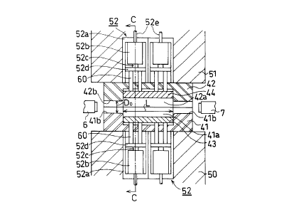
Figs. l(a) and l(b) are sectlonal views showing an
embodiment of a hydroforming apparatus of the present
invention. Fig. l(a) is a longitudinal sectional view of
the apparatus, and Fig. l(b) is a sectional view taken along
the line C-C of Fig. l(a).
A die is composed of a lower die 41 and an upper die
42. The lower die 41 is attached to a bolster 50 of an
CA 02244~48 1998-08-0~
unillustrated press unit. The upper die 42 is attached to a
ram head 51 of the unillustrated press unit.
The ram head 51 is moved vertically by an
unillustrated hydraulic cylinder, thereby pressing the upper
die 42 against the lower die 41 with a predetermined force.
The bolster 50 and the ram head 51 respectively contain
pressure units 52 in a vertically opposing manner.
In Fig. l(a), two pressure units 52 are installed in
each of the bolster 50 and the ram head 51. However, the
number of the pressure units 52 is not particularly limited.
Each of the pressure units 52 includes a case 52a, a
cylinder 52b, a piston rod 52c, and a piston head 52d. A
hydraulic fluid is fed into the cylinder 52b from an
unillustrated pump through a line 52e or 52f to thereby move
the piston rod 52c vertically. Accordingly, the piston head
52d is moved vertically while being guided along the inner
walls of the case 52a.
The lower die 41 and the upper die 42 have die
cavities (spaces formed in the dies) 41a and 42a and tube-
holding grooves 41b and 42b formed respectively therein in a
vertically opposing manner. The die cavities 41a and 42a
contain pads 43 and 44, respectively. A space defined by
the side walls of the die cavities 41a and 42a and the pads
43 and 44 is used to form an expanded portion of a product.
Specifically, a length L and a width D2 of the die cavities
41a and 42a are respectively identical to the length and
width of an expanded portion 2a (3a) of the product of Fig.
22
CA 02244~48 1998-08-0~
7(bl) (Fig. 7(cl)). A diameter Do of the tube-holding
grooves 41b and 42b is identical to the outer diameter of a
metallic tube 1. Pins 60 are set between the pads 43 and 44
and the upper and lower piston heads 52d. As the piston
rods 52c move vertically, the pads 43 and 44 also move
vertically. The upper pad 44 and the upper pins 60 are
connected to, for example, the piston head 52d located on
the ram head side, in order to prevent the pad 44 and the
pins 60 from dropping.
The secondary hydroforming can be carried out with
only a single pad elther upper pad 44 or lower pad 43, and
also with several pads of upper and/or lower pad.
Figs. 2(al), 2(a2), 2(bl), 2(b2), 2(cl), and 2(c2)
are views showing a die portion of the apparatus of Fig.
l(a), illustrating a method for hydroforming a metallic tube
through use of the apparatus so as to obtain a product 2.
Figs. 2(al), 2(bl), and 2(cl) are longitudinal sectional
views showing the state of a metallic tube being set in the
upper and lower dies, the state of the metallic tube being
primary-hydroformed, and a state of the metallic tube being
secondary-hydroformed, respectively. Figs. 2(a2), 2(b2),
and 2(c2) are sectional views taken along the C-C lines of
Figs. 2(al), 2(bl), and 2(cl), respectively.
The metallic tube 1 is set in the tube-holding
grooves 4lb of the lower die 41. An unillustrated ram head
is lowered from above so as to press the upper die 42
against the lower die 41 attached to an unillustrated
CA 02244~48 1998-08-0~
bolster with a predetermined force. Sealing-punch 6 and 7
are advanced from their respective sides so that head
portions 6a and 7a of the sealing-punch 6 and 7,
respectively, are tightly inserted into the end portions of
the metallic tube 1, thereby the tube ends are sealed during
hydroforming. Next, while a hydraulic fluid 8 is introduced
into the metallic tube 1 by means of an unillustrated pump
through a path 6b extending through the left-hand sealing
punch 6, air inside the metallic tube 1 is ejected through a
path 7b extending through the right-hand sealing punch 7,
thereby filling the interior of the metallic tube 1 with the
hydraulic fluid 8.
Subsequently, primary hydroforming is performed. The
pressure of the hydraulic fluid 8 is increased advancing the
sealing-punch 6 and 7 to press,the metallic tube 1 axially,
thereby primary-expanding the tube material within the die
cavities 41a and 42a (Fig. 2(al)) as shown in Figs. 2(bl)
and 2(b2). The primary expansion is performed such that a
circumferential length of a primary expanded portion 2a'
becomes equal to or slightly shorter than a circumferential
length of the expanded portion 2a of the product 2 of Fig.
7(bl)-
A circumferential length of a primary expandedportion is made equal to or slightly shorter than a
circumferential length of an expanded portion of a product
for the following reason. If a circumferential length of a
primary expanded portion is longer than that of an expanded
24
CA 02244~48 1998-08-0~
portion of a product, a shape defect, such as wrinkles, will
occur in secondary hydroforming. In the case that a
circumferential length of a primary expanded portion is made
slightly shorter than a circumferential length of an
expanded portion of a product, the circumferential length of
the primary expanded portion is made about 2% to 3% shorter
than that of the product. This about 2%-3% shortage in the
circumferential length of the primary expanded portion can
be removed through further expansion of the primary expanded
portion effected by increasing the fluid pressure in
secondary hydroforming, thereby obtaining the
circumferential length of the expanded portion of the
product. In the case of an about 2%-3% length shortage in
primary hydroforming, wall thinning involved in expansion
effected by secondary hydroforming is negligible. However,
in this case, since fluid pressure must be increased, the
hydroforming apparatus must be designed accordingly.
The primary expanded portion 2a' has an elliptical
cross-sectional profile. The elliptical shape is selected
so that the entire cross section can be extended in a
circumferential direction as uniformly as possible. The
cross-sectional profile is not particularly limited. Since
the radius of a round section of the expanded portion 2a' is
greater than the corner radius of the expanded portion 2a of
the product 2, fluid pressure for primary hydroforming can
be made relatively small.
Subsequently, the pressure of the hydraulic fluid 8
CA 02244~48 1998-08-0~
is adjusted to a secondary hydroforming pressure, which will
be described later, to thereby perform secondary
hydroforming. Specifically, the pressure units 52 of Fig. 1
are activated, so that the primary expanded portion 2a' is
pressed from above and from underneath with the pads 43 and
44 via the pins 60 as shown in Fig. 2(cl). Thus, the cross-
sectional profile of the primary expanded portion 2a' is
formed to that of the expanded portion 2a of the product 2.
In the above-mentioned secondary hydroforming, the
tubular material is supported from inside by the pressure of
the hydraulic fluid 8. Accordingly, the cross-sectional
profile is not deformed to a cocoon shape as shown in Fig.
12(b2). In other words, fluid pressure for secondary
hydroforming may be to such a degree as to prevent
deformation to a cocoon shape, specifically 100-200 atm, for
example.
A required circumferential length of an expanded
portion of a product is already obtained in primary
hydroforming. Accordingly, corner portions of a cross
section of the product's expanded portion are formed through
bending deformation, not through fluid pressure. Thus, the
hydroforming method of the present invention has a
significant advantage that it can not only suppress wall
thinning at corner portions but also obtain a relatively
small corner radius with a relatively low fluid pressure.
Figs. 3(al), 3(a2), 3(bl), 3(b2), 3(cl), and 3(c2)
are views showing a die portion of the apparatus shown in
26
CA 02244~48 1998-08-0~
Fig. l(a), illustrating another method for hydroforming a
metallic tube through use of the apparatus so as to obtain a
product 3. Figs. 3(al), 3(bl), and 3(cl) are longitudinal
sectional views showing a state of a metallic tube being set
in the upper and the lower dies, a state of the metallic
tube being primary-hydroformed, and a state of the metallic
tube being secondary-hydroformed, respectively. Figs. 3(a2),
3(b2), and 3(c2) are sectional views taken along the C-C
lines of Figs. 3(al), 3(bl), and 3(cl), respectively.
The metallic tube 1 is set in the tube-holding
grooves 4lb of the lower die 41. An unillustrated ram head
is lowered from above so as to press the upper die 42
against the lower die 41 attached to an unillustrated
bolster with a predetermined force. Sealing-punch 6 and 7
are advanced from their respective sides so that head
portions 6a and 7a of the sealing-punch 6 and 7,
respectively, are tightly inserted into the end portions of
the metallic tube 1, thereby the tube ends are sealed during
hydroforming. Next, while a hydraulic fluid 8 is introduced
into the metallic tube 1 by means of an unillustrated pump
through a path 6b extending through the left-hand sealing
punch 6, air inside the metallic tube 1 is ejected through a
path 7b extending through the right-hand sealing punch 7,
thereby filling the interior of the metallic tube 1 with the
hydraulic fluid 8.
Subsequently, primary hydroforming is performed. The
pressure of the hydraulic fluid 8 is increased advancing the
CA 02244~48 1998-08-0~
sealing-punch 6 and 7 to press the metallic tube axally,
thereby primary-expanding the tube material within the die
cavities 41a and 42a (Fig. 3(al)) as shown in Figs. 3(bl)
and 3(b2). The primary expansion is performed such that a
circumferential length of a primary expanded portion 3a' as
measured at a wall center region of the expanded portion 3a'
becomes equal to or slightly shorter than the
circumferential length of the expanded portion 3a of the
product 3 of Fig. 7(cl) as measured at a wall center region
of the expanded portion 3a.
Accordingly, when the circumferential length of the
metallic tube 1 is identical to that of the expanded portion
3a of the product 3, primary hydroforming as shown in Fig.
3(bl) is unnecessary.
The primary expanded portion 3a' in Fig. 3(b2) has a
circular cross-sectional profile. The circular shape is
selected so that the entire cross section can be extended in
a circumferential direction as uniformly as possible. The
cross-sectional profile is not particularly limited. Since
the radius of the expanded portion 3a' is greater than the
corner radius of the expanded portion 3a of the product 3,
fluid pressure for primary hydroforming can be made
relatively small.
Subsequently, the pressure of the hydraulic fluid 8
is set to a secondary hydroforming pressure, to thereby
perform secondary hydroforming. Specifically, the pressure
units 52 of Fig. 1 are activated, so that the primary
28
CA 02244~48 1998-08-0~
expanded portion 3a' is pressed from above and from
underneath with the pads 43 and 44 via the pins 60 as shown
in Fig. 3(cl). Thus, the cross-sectional profile of the
primary expanded portion 3a' is formed to that of the
expanded portion 3a of the product 3.
In the above-mentioned secondary hydroforming, the
tubular material is supported from inside by the pressure of
the hydraulic fluid 8. Accordingly, the cross-sectional
profile is not deformed to a cocoon shape as shown in Fig.
12(b2). The fluid pressure for secondary hydroforming may be
low pressure, specifically 100-200 atm for example, because
the pressure is only required to privent the occurrence of a
cocoon shape. Also, in this case, since a required
circumferential length of an expanded portion of a product
is already obtained in primary hydroforming, a required
cross-sectional corner radius of a product's expanded
portion can be obtained at a relatively low fluid pressure
while wall thinning at corner portions is suppressed.
As describe above, according to the present invention,
when hydroforming is performed to obtain the products 2 and
3 and like products, wall thinning at corner portions of a
cross section of an expanded portion can be suppressed.
Thus, even when a tube material having a relatively high
strength and poor ductility is hydroformed, the corner
radius of a product's expanded portion can be finished to a
relatively small value.
Also, since the pressure of hydraulic fluid required
29
CA 02244~48 1998-08-0~
is relatively low, the cost of hydroforming equipment
becomes comparatively low, thereby reducing hydroforming
cost. Further, according to the present invention,
hydroforming for obtaining the product 3 does not require a
flattening process for a metallic tube as shown in Figs.
12(al) and 12(bl). Accordingly, the obtained product 3 is
free from a concave shaped defect shown in Fig. 14(c).
Tubular parts according to the present invention are
not limited to those whose expanded portions have
rectangular cross sections as shown in Figs. 7(b2) and 7(c2).
Figs. 4(a) to 4(c) show example cross sections of
expanded portions of tubular parts according to the present
invention. Even these special-shaped products can be
obtained through selection of corresponding pad shapes and
die cavity shapes.
Tubular parts according to the present invention are
not limited to linear products as shown in Figs. 7(bl) and
7(cl).
Figs. 5(a), 5(b), and 5(c) show an example of a bent
hydroformed product. Fig. 5(a) is a plan view of the
product. Fig. 5(b) is a sectional view showing an expanded
portion of the product. Fig. 5(c) is a sectional view
showing another expanded portion of the product.
The present invention is applicable to the
hydroforming of a bent product such as the product 70 shown
in Fig. 5. The product 70 includes a plurality of expanded
portions 70a, 70b, and 70c and cylindrical portions 70d, 70e,
CA 02244~48 1998-08-0~
and 70f having the same diameter as that of a metallic tube.
Fig. 5(b) shows a cross section of the cylindrical portion
70b. Fig. 5(c) shows a cross section of the cylindrical
portion 70c.
Fig. 6 is an example of a plan view showing the
arrangement of pressure units attached to a bolster and to a
ram head of a hydroforming apparatus for forming a bent
product.
A hydroforming apparatus for hydroforming a bent
product includes a bolster 50 and a ram head 51 as shown in
Fig. 6. A plurality of pressure units 52-1 to 52-6 are
attached to the bolster 50 and to the ram head 51 and
arranged as shown in Fig. 6. In order to hydroform a
product having a plurality of expanded portions, a plurality
of pressure units corresponding to the expanded portions may
be used. For example, in order to hydroform the product 70
of Fig. 5(a), the pressure units 52-4, 52-2, and 52-6
corresponding to the expanded portions 70a, 70b, and 70c may
be activated.
The pressure units can be controlled independently of
each other so as to independently control their applied
pressures and strokes as needed.
A metallic tube may be of any metal, such as steel,
aluminum, copper, or the like.
EXAMPLES
Example 1:
31
CA 02244~48 1998-08-0~
The product 2 of Fig. 7(bl) was hydroformed. Product
dimensions were as follows: D1=90 mmi D2=90 mm; R=6 mm;
L=400 mm, L1=500 mm; Do=89.1 mm.
A hydroforming apparatus having the bolster 50 and
the ram head 51 as shown in Fig. 1 was used to carry out a
hydroforming method of the present invention. Each of the
bolster 50 and the ram head 51 had two built-in pressure
units 52. Each pressure unit 52 had a maximum thrust of 40
tons an a maximum stroke of 100 mm.
The metallic tube 1 was a steel tube for machine
purposes, STKM12A (JIS G 3445), and had an outer diameter of
89.1 mm, a wall thickness of 2.3 mm, and a length Lo of 600
mm. The metallic tube 1 was set in the lower die 41 as
shown in Fig. 2(al). The upper die 42 was pressed against
the lower die 41 with a die clamping force of 150 tons. The
sealing punches 6 and 7 were sealed against corresponding
tube ends. The metallic tube 1 was filled with the
hydraulic fluid 8, which was an emulsion prepared by
dispersing a fat-and-oil component in water in an amount of
3%. Next, as shown in Fig. 2(bl), while the sealing punches
6 and 7 were being advanced, the pressure of the hydraulic
fluid 8 was increased to 300 atm. Thus, primary
hydroforming was performed to thereby form the expanded
portion 2a' having a circumferential length of 350 mm. A
maximum axial force was 40 tons. The primary expanded
portion 2a' had an elliptical cross section having a minimum
diameter of 90 mm and a maximum diameter of 124 mm.
CA 02244~48 1998-08-0~
Next, after the fluid pressure was reduced to 150 atm,
the pressure units 52 were activated so as to press the
primary expanded portion 2a' in a direction of its major
axis with the upper and lower pads 43 and 44. Thus,
secondary hydroforming was performed to thereby obtain the
expanded portion 2a having a square cross section measuring
a height and a width of 90 mm as shown in Fig. 2(cl),
yielding the product 2. The corner radius R of a cross
section of the expanded portion 2a was 6 mm as required. A
minimum wall thickness was 2.0 mm, which satisfied a
required wall thickness of 1.8 mm for the product 2.
A metallic tube similar to the above metallic tube 1
was hydroformed according to a conventional hydroforming
method. As shown in Fig. 9(al), the metallic tube was set
in the lower die 4. The upper die 5 was pressed against the
lower die 4 with a die clamping force of 450 tons. The
sealing punches 6 and 7 were sealed against corresponding
tube ends. The metallic tube was filled with the hydraulic
fluid 8, which was an emulsion prepared by dispersing a fat-
and-oil component in water in an amount of 3%. Next, as
shown in Fig. 9(bl), the pressure of the hydraulic fluid 8
was increased to 900 atm advancing the sealing-punch 6 and 7,
thereby forming the expanded portion 2a. A maximum axial
force was 80 tons. The corner radius R of a cross section
of the expanded portion 2a was 14 mm. A minimum wall
thickness of the expanded portion 2a was 1.8 mm, which was a
required wall thickness for the product 2. Since a further
CA 02244~48 1998-08-0~
increase in fluid pressure causes a failure to meet the
target wall thickness of the product 2, a target corner
radius of 6 mm of the product 2 could not be attained.
As described above, the hydroforming method of the
present invention was smaller in die clamping force, axial
force, and fluid pressure than the conventional hydroforming
method. Further, the corner radius of a cross section of an
expanded portion could be made smaller than in the case of
the conventional method.
Example 2:
The product 3 of Fig. 7(cl) was hydroformed. Product
dimensions were as follows: D1=50 mm; D2=137 mm; R=14 mm;
L=400 mm, Ll=500 mm; Do=89.1 mm.
A hydroforming apparatus having the bolster 50 and
the ram head 51 as shown in Fig. 1 was used to carry out a
hydroforming method of the present invention. Each of the
bolster 50 and the ram head 51 had two built-in pressure
units 52. Each pressure unit 52 had a maximum thrust of 40
tons an a maximum stroke of 100 mm.
The metallic tube 1 was a steel tube for machine
purposes, STKM12A (JIS G 3445), and had an outer diameter of
89.1 mm, a wall thickness of 2.0 mm, and a length Lo of 600
mm. The metallic tube 1 was set in the lower die 41 as
shown in Fig. 3(al). The upper die 42 was pressed against
the lower die 41 with a die clamping force of 150 tons. The
sealing punches 6 and 7 were sealed against corresponding
34
CA 02244~48 1998-08-0~
tube ends. The metallic tube 1 was filled with the
hydraulic fluid 8, which was an emulsion prepared by
dispersing a fat-and-oil component in water in an amount of
3%. Next, as shown in Fig. 3(bl), the pressure of the
hydraulic fluid 8 was increased to 150 atm with advancing
the sealing-punch 6 and 7. Thus, primary hydroforming was
performed to thereby form the expanded portion 3a' having a
circular cross-section which has a circumferential length of
350 mm.
A maximum axial force was 32 tons. Next, while the
fluid pressure was held at 150 atm, the pressure units 52
were activated so as to press the primary expanded portion
3a' in a vertical direction with the upper and lower pads 43
and 44. Thus, secondary hydroforming was performed to
thereby obtain the expanded portion 3a having a rectangular
cross section measuring a height D1 of 50 mm and a width D2
of 150 mm as shown in Fig. 3(cl), yielding the product 3.
The corner radius R of a cross section of the expanded
portion 3a was 14 mm as required. A minimum wall thickness
was 1.8 mm, which satisfied a required wall thickness of 1.6
mm for the product 3.
Next, a metallic tube similar to the above metallic
tube 1 was hydroformed according to a conventional
hydroforming method. As shown in Fig. 12(al), the plugs 32b
having an outer diameter of 84.5 were inserted into
corresponding tube ends. The thus-arranged metallic tube
was flattened as shown in Fig. 12(bl), obtaining D1'=48 mm
CA 02244~48 1998-08-0~
and D2'=110 mm (Fig. 12(b2)). Subsequently, as shown in Fig.
13(al), the thus-flattened metallic tube was set in the
lower die 14. The upper die 15 was pressed against the
lower die 14 with a die clamping force of 500 tons. The
sealing punches 6 and 7 were sealed against corresponding
tube ends. The metallic tube was filled with the hydraulic
fluid 8, which was an emulsion prepared by dispersing a fat-
and-oil component in water in an amount of 3%.
Next, as shown in Fig. 13(bl), while the sealing
punches 6 and 7 were held stationary, fluid pressure was
increased to 700 atm, yielding the product 3 having the
expanded portion 3a. The corner radius R of a cross section
of the expanded portion 3a was 14 mm. A wall thickness of
the expanded portion 3a was 1.6 mm, which was a required
wall thickness for the product 3.
However, the concave 34 (Fig. 14(c)) having a depth
of 2 mm and a width of 8 mm remained in a flat surface of
the expanded portion 3a. Thus, the product 3 free of the
shape defect could not be obtained.
As described above, the hydroforming method of the
present invention is smaller in die clamping force and fluid
pressure than the conventional hydroforming method. Further,
the obtained product 3 is such that the degree of wall
thinning of its expanded portion is relatively small and a
concave or like shape defects are not formed.
According to a hydroforming method and a hydroforming
apparatus of the present invention, wall thinning at corner
36
CA 02244~48 1998-08-0~
portions of a cross section of an expanded portion can be
suppressed. Thus, the present invention allows the wall
thickness of a metallic tube to be minimized and is
applicable to the hydroforming of a tube material having a
relatively poor ductility.
Also, according to the present invention, a metallic
tube does not need to be flattened so as to be received in a
die. Thus, no concave defect remains in a hydroformed
product. Further, the pressure of a hydraulic fluid for
hydroforming can be made relatively low, a die clamping
force imposed by a ram head and an axial force can be
reduced. These features lead to a reduction in hydroforming
equipment cost. Since reduced fluid pressure allows the
strength of a hydroforming die to be reduced, die cost can
be reduced. Thus, the present invention yields a
significant effect of reducing tube hydroforming cost.