Note: Descriptions are shown in the official language in which they were submitted.
CA 02244929 1998-07-31
WO 97/28658 PCTllJS9710l52!
1
METHOD AND APPARATUS FOR PROVIDING A PRIVATE
COMMUNICATION SYSTEM IN A PUBLIC SWITCHED
TELEPHONE NETWORK
BACKGROUND OF THE INVENTION
' I. Field of the Invention
The present invention relates generally to multiparty communication
systems, and, more particularly, to a point-to-multipoint private
communication network directly incorporated within a cellular or land line
telephone system.
II. Description of the Related Art
Mobile cellular telephone service has been in use for some time, and
traditionally has been characterized by a central site transmitting with high
power to a limited number of mobile or portable units in a large geographic
area. In early cellular systems only a limited number of radio channels were
available, thus limiting the number of radiotelephone conversations within
an entire metropolitan area to the number of channels available.
Modern cellular radiotelephone systems have a comparatively large
number of radio channels, which may be effectively multiplied by using
identical channel frequencies within the differing smaller coverage areas
(i.e., "cells") comprising a given service territory. Each cell includes a
cell-site transmitter, or base station, which broadcasts at a power level
selected to ensure signal reception at the cell boundary without unduly
interfering with reception in adjacent cells. This allows channel frequencies
used in one cell to be reused in another cell geographically separated
therefrom according to a predetermined plan. Thus, a large number of
channels can be made available in a metropolitan area and the service
provided thereby can be identical to a standard wire line telephone.
Numerous standards exist for the implementation of cellular
telephone communications. These standards include the advanced mobile
° 35 phone system (AMPS), Global System for Mobile communication (GSM),
and Code Division Multiple Access (CDMA). The spread spectrum
~ modulation technique of CDMA has significant advantages over other
modulation techniques for multiple access communication systems. For
example, the use of CDMA results in a much higher spectral efficiency than
can be achieved using other multiple access schemes.
CA 02244929 1998-07-31
WO 97/28658 PCT/US97/01521
2
Although recent development efforts have enabled CDMA and other
cellular systems to effectively provide "point-to-point" communication
links between users, various public and private agencies have nonetheless
continued to rely upon dedicated land mobile radio (LMR) communication
networks. This results from the incapability of cellular systems to establish
'
"point-to-multipoint" communication networks among a set of member
users. For example, local law-enforcement agencies utilize LMR networks '
in which a closed radio communication system is established through
repeater stations. Such closed LMR networks are often characterized by
push-to-talk (PTT) operation, in which users depress a handset talk button
or the like when desiring to broadcast voice information to other member
users. However, the infeasibility of providing repeater stations over a large
geographic area limits the extent to which the set of member users may be
geographically dispersed.
Although both cellular and conventional land line telephone systems
are capable of facilitating communication between widely separated users,
closed "PTT-type" communication networks have not hitherto been
incorporated within either type of system. This may be due in part to the
absence of a convenient mechanism for automatically joining. an identified
set of users into such a closed network. Moreover, even if such a
mechanism were available, both types of systems are easily compromised by
unauthorized third parties and are thus unsuitable for secure
communication.
The conference calling capability provided by both cellular and Iand
line carriers is also an unsuitable surrogate for a PTT-type communication
network. In particular, conference calling between users within different
cellular or land line systems requires some degree of prior coordination with
the responsible service provider. Moreover, in many conference calling
systems the information signals from the conference call participant are
combined and the resultant composite signal universally provided to each
such participant. This effectively precludes separately encrypting each such
information signal as a means of increasing communication security, since
the separately encrypted information signals would generally not be
recoverable from the composite signal.
Accordingly, it is an object of the present invention to incorporate a
private communication network directly within a cellular and/or land line
telephone system in such a way as to obviate the need for prior coordination
with a telephone service provider.
CA 02244929 1998-07-31 ,
WO 97/28658 PCT/US97/01521
3
It is another object of the invention that the private communication
network emulate an LMR network characterized by PTT operation.
It is yet another object of the present invention that control of the
private communication network be resident within a network call manager
separately connected to an existing land line telephone system.
It is a further object of the present invention that encryption
' techniques be capable of application within the private communication
network as a means of enhancing communication security.
SUMMARY OF THE INVENTION
The present invention is directed to a private communication
network through which a plurality of member users communicate using the
public switched telephone network (PSTN). Each member user utilizes
I5 either a modified land line telephone directly connected to the PSTN, or
uses a modified mobile telephone operatively coupled to the PSTN through
a wireless communication system. The private communication network
includes a network call manager having a telephone network interface for
establishing a telephone connection with each of a plurality of telephone
lines of the PSTN. Each of the plurality of telephone lines is associated with
one of the plurality of member users.
The network call manager further includes a telephone line switch
matrix, coupled to the telephone network interface, for providing an
information signal received from an active member user over a selected
telephone line to the remaining non-active member users. A network
manager controller identifies the active member user the basis of
push-to-talk (PTT) request signals received from the member users'
telephones over the plurality of telephone lines. The active member user
may be identified as, for example, the member user from which a PTT
request signal is first received after the previously active member user has
relinquished speaking privileges. Alternately, the active member user may
be chosen by using predefined user priority criteria to evaluate all PTT
request signals queued by the network call manager.
The telephone set of each member user will typically be capable of
both standard telephone operation, and of PTT operation over the private
. communication network. When configured for PTT operation, each
telephone set receives and digitally processes input voice or data
information from a member user. The resultant vocoder data packets, as
well as any PTT request signals initiated by the member user, are then
CA 02244929 2004-08-03
74769-128
4
supplied to a modem for reverse link transmission via the
PSTN to the telephone network interface of the network call
manager. The security of the PTT private network may be
enhanced by configuring each telephone set for encryption of
all such reverse link transmissions, as well as for
corresponding decryption of the forward link information
from the active member user.
The invention may be summarized according to one
aspect as in a communication system in which users
communicate through a switched telephone network, a private
communication network for facilitating communication among a
plurality of member user telephone sets said private
communication network comprising: a network call manager
including: a telephone network interface for establishing a
telephone connection with each of said plurality of member
users over a plurality of channels of said switched
telephone network, respectively, a switch matrix, coupled to
said ~'elephone network interface, for providing an
information signal received by said telephone network
interface over one of said plurality of channels
simultaneously to a plurality of others of said channels via
said telephone network interface, and a controller for
configuring said switch matrix in response to talk request
signals received over a selected one of said plurality of
channels; and a plurality of eligible member user telephone
sets disposed for simultaneous communication over said
plurality of channels, each of said eligible member user
telephone sets including means for generating one of said
talk request signals, at least some of said eligible member
user telephone sets being connected to the private
communication network through a wireless communications
system.
CA 02244929 2004-08-03
74769-128
4a
According to another aspect~the invention provides
in a communication system in which users communicate through
a switched telephone network, a network call manager for
facilitating private communication simultaneously among a
plurality of member user telephone sets, at least some of
said member user telephone sets being connected to the
private communication network through a wireless
communications system, said network call manager comprising:
a telephone network interface for establishing a telephone
connection with each of a plurality of said member user
telephone sets, including at least a plurality of said
member user telephone sets that are connected to the private
communication network through the wireless communications
system, over a corresponding plurality of channels of said
switched telephone network; a switch matrix, coupled to skid
telephone network interface, for providing an information
signal received over a selected one of said plurality of
channels simultaneously to other ones of said plurality of
channels via said telephone network interface; and
controller means for configuring said switch matrix in
response to control information received over at least one
of said plurality of channels.
According to yet another aspect the invention
provides in a private communication network system in which
users communicate through a switched telephone network, a
method for facilitating private communication among a
plurality of eligible member user telephone sets, at least
some of said eligible member user telephone sets being
connected to the private communication network through a
wireless communications system, said method comprising the
steps of: establishing a telephone connection between a
network call manager and each of a plurality of telephone
channels of said switched telephone network, each of said
CA 02244929 2004-08-03
74769-128
4b
plurality of telephone channels being associated with one of
said plurality of eligible member user telephone sets;
providing an information signal received at said network
call manager over a selected one of said plurality of
telephone channels from an active one of said eligible
member user telephone sets simultaneously to a plurality of
other ones of said eligible member user telephone sets over
other ones of said plurality of telephone channels;
generating talk request signals substantially simultaneously
at a plurality of said eligible member telephone sets for
transmission to said network call manager via said switched
telephone network; and choosing said active eligible member
user telephone set on the basis of said talk request signals
received at said network call manager.
According to still another aspect the invention
provides in a communication system in which users
communicate through a switched telephone network, a private
communication network for facilitating communication among a
plurality of member user telephone sets, said private
communication network comprising: a network call manager
including: a telephone network interface for establishing a
telephone connection with each of a plurality of telephone
lines of said switched telephone network, each of said
plurality of telephone lines being associated with one of
said plurality of member user telephone sets, a switch
matrix, coupled to said telephone network interface, for
providing an information signal received over a selected one
of said plurality of telephone lines simultaneously to other
ones of said plurality of telephone lines via said telephone
network interface, and controller means for configuring said
switch matrix in response to talk request signals received
over said plurality of telephone lines; and a plurality of
eligible member user telephone sets, at least some of said
CA 02244929 2004-08-03
74769-128
4c
eligible member user telephone sets being connected to the
private communication network through a wireless
communications system, disposed for simultaneous
communication over said plurality of telephone lines, each
of said eligible member user telephone sets including means
for generating one of said talk request signals. ,
BRIEF DESCRIPTION OF THE DRAWINGS
Additional objects and features of the invention
will be more readily apparent from the following detailed
description and appended claims when taken in conjunction
with the drawings, in which:
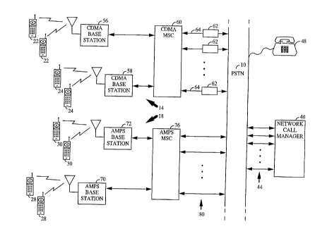
FIG. 1 illustratively represents the elements of
an exemplary telephone system within which may be
established a PTT point-to-multipoint private communication
network of the present invention;
FIG. 2 is a block diagram of an exemplary network
call manager of the PTT private network of the present
invention
FIG. 3A shows a block diagram of a land line PTT
dual-mode telephone comprised of a transmit section and a
receive section
FIG. 3B depicts the land line dual mode PTT
telephone of FIG. 3A as modified to facilitate encrypted
communication within a PTT private network;
FIG. 4 is a block diagram of an AMPS dual-mode PTT
telephone:
FIG. 5 is a block diagram of a CDMA cellular
telephone configured for use within a PTT private network of
the present invention;
CA 02244929 2004-08-03
74769-128
4d
FIG. 6 provides a functional'block diagram of a
network call manager designed for employment within a PTT
private network in which signaling is effected using analog
tones; and
FIG. 7 shows a land line telephone configured for
communication with a network call manager using analog
tones.
DETAILED DESCRIPTION OF TFiE PREFERRED EMBODIMENTS
I. Structure of PTT Private Network
FIG. 1 illustratively represents the elements of
an exemplary telephone system within which may be
established a PTT point-to-multipoint private communication
network ("PTT private network") of the present invention.
Referring to FIG. 1, the exemplary
CA 02244929 1998-07-31
'WO 97128658 PCTlF1S97/01523
telephone system includes a public switched telephone network (PSTN) 10, a
CDMA cellular communication system 14 and an analog (AMPS) cellular
communication system 18. The CDMA system 14 provides service to
CDMA-compatible mobile radiotelephones ("CDMA mobiles") 22 and 24,
5 while the AMPS system 18 facilitates communication with users of
AMPS-compatible mobile radiotelephones ("AMPS mobiles") 28 and 30. A
' network call manager 40, connected through a plurality of T1 channels 44 to
the PSTN 10, operates as described hereinafter to create a private
communication network among a corresponding plurality of member users
within the exemplary telephone system of FIG. 1.
The private communication network may include member users
serviced by one or both of the CDMA and AMPS cellular systems 14 and 18,
and/or may include one or more member users directly connected to the
PSTN 10 through modified land line telephones such as the telephone 48.
Although CDMA and AMPS cellular systems are shown as being
incorporated within the exemplary embodiment of FIG. 1, it is to be
understood that the teachings of the present invention are pertinent to
other cellular air interface standards as well for example Global System for
Mobile Communications (GSM) and Time Division Multiple Access
(TDMA). A brief description of the constituent elements of the CDMA and
AMPS cellular communication systems 14 and 28 shown in FIG. 1 will be
provided prior to discussion of the operative principles of the present
invention.
The CDMA cellular communication system 14 includes a plurality of
cells, two of which are identified in FIG. 1 as including cell-sites (i.e.,
"base
stations") 56 and 58. Each cell may be partitioned into a number of sectors,
where communication with CDMA mobiles 22 and 24 within a given sector
is handled by a cell-site transceiver providing radio coverage over the
sector.
The base stations 56 and 58 operate to receive and transmit the signals
enabling a radio transceiver within each CDMA mobile to communicate
with the PSTN 10. In the CDMA system 14, data packets are used in the
over-the-air exchange of information between the base stations 56 and 58
and the CDMA mobiles 22 and 24.
Telephone calls are routed by the cell-site base stations 56 and 58
between the CDMA mobiles 22 and 24 and a CDMA mobile switching center
(MSC) 60, which will typically be located within a mobile telephone
switching office {not shown). The primary purpose of the MSC 60 is to
provide voice path connections between the CDMA mobiles 22 and 24 and
the PSTN 10. To this end the MSC 60 performs functions such as, rating data
CA 02244929 1998-07-31
WO 97/28658 PCTIUS97/01521
6
between a MSC modems &2 and CDMA mobiles 22 and 24 by way of the
appropriate CDMA base station 56 or 58. The MSC 60 also performs other
tasks, including paging of a CDMA mobile when a call is received from the
PSTN 10 and switching calls to available PSTN lines via a plurality of T1
channels 64. A set of MSC modems 62 serves to convert the digital
information signals received from the CDMA mobiles 22 and 24 to analog
signals suitable for transmission over the PSTN 10, and likewise converts
analog signals from the PSTN 10 to digital signals subsequently provided to
the CDMA mobiles 22 and 24.
The AMPS cellular communication system 18 also includes a number
of cells, two of which are identified in FIG. 1 as including cell-site base
stations 70 and 72. Each cell may be partitioned into a number sectors, where
communication with AMPS mobiles ~28 and 30 within a given sector is
handled by a cell-site transceiver providing radio coverage over the sector.
Telephone calls are routed by the cell-site base stations 70 and 72 between
the
AMPS mobiles 28 and 30 and an AMPS mobile switching center
(MSC) 76, which is coupled to the PSTN 10 via a plurality of T1 channels 80.
II. Operation of PTT Private Network
Turning now to FIG. 2, reference will be made to a block diagram of
an exemplary network call manager 40 in describing operation of the PTT
private network of the present invention. The manner in which the land
line or cellular telephones associated with each member user are configured
for cooperation with the network call manager 40 will be described below
with reference to FIGS. 3-5. In what follows, communication links from the
modified land line telephone 48, from the AMPS mobiles 28 and 30, and
from the CDMA mobiles 22 and 24, to the network call manager 40 via the
PSTN 10 are termed "reverse Iinks". The reverse link associated . with the
member user currently designated by the network call manager 40 as the
active member user is assumed to be the only one of the reverse links
carrying valid voice or data information. Ail other reverse links are
available for use in providing signaling information to the network call
manager 40. Each "forward link" through the PSTN 10 from the network ,
call manager 40 to each member user carries the voice or data information
provided by the active member user. As is described herein, the network ,
call manager 40 is reconfigured upon each new identification of an active
member. This reconfiguration results in the reverse link voice or data
information from the newly identified active member user being provided
CA 02244929 1998-07-31
WO 97/28658 PCT/US97/01521
7
to fhe forward links associated with ail other member users, including the
forward link of the previously active member user.
The network call manager 40 includes a network controller 90, within
which is stored at least one list of the telephone numbers associated with the
' 5 member users of a first PTT private network. When desiring to access the
first PTT private network, a calling member user dials an access number
' identifying the first PTT private network. The. network controller 90 may
also store other lists of member users, each list being associated with a
unique access number and defining a separate PTT private networks.
The network call manager 40 is designed to appear to the PSTN 10 as
would a private branch exchange (PBX) system, and thus the call placed by
the calling member user may be received over any one of the T1
channels 44. In this regard a telephone network (T1) interface 92 is provided
for forming a connection between the T1 channel 44 associated with the
calling member user and one of a plurality of network manager modems 98.
As is described herein, the T1 interface 92 also serves to connect various
other ones of the network manager modems 98 to ones of the T2 channels
44 associated with other member users.
If the calling member user is serviced by the CDMA cellular
system 14, a telephone connection is established when the network call
manager modem 98' coupled to the T1 channel 44 receiving the incoming
call becomes synchronized with the one of the MSC modems 62 (FIG. 1)
assigned to the call. Fox a calling member user having a land line telephone
or AMPS cellular telephone, a similar telephone connection is established
upon synchronization of an internal modem (FIGS. 3A and 4) within the
member user's telephone and the network manager modem 98' receiving
the incoming call. In an exemplary embodiment the network manager
modems 98 comprise, for example, so-called "AMPS modems" especially
well-suited for over-the-air information transfer.
Upon an incoming call to a PTT private network being received from
a member user over one of the T1 channels 44, the T1 interface 92 uses
standard techniques to determine the access number dialed during
placement of the call. The dialed access number, which corresponds to a
given PTT private network, is communicated by the T1 interface 92 to the
network controller 90. The T1 interface also connects the T1 channel 44
associated with the calling member user to an available network manager
modem (e.g., network manager modem 98'). Once modem synchronization
has been achieved, the network controller 90 may require the calling user to
furnish authentication information used for verification of the calling
CA 02244929 1998-07-31
WO 97/28658 PCT/US97/01521
8
user's membership in the PTT private network identified as corresponding
to the called access number. Upon confirmation of such membership, the
network controller 90 may command either the T1 interface 92 or a selected
network manager modem 98 to initiate paging of the remaining member
users of the identified PTT private network. It is noted that in alternate
embodiments the T1 interface 92 may comprise an E1 interface, or various
other digital or "PBX-type" interfaces. '
Upon a first of the other member users of the identified PTT private
network answering a network page (i.e., a telephone call} issued by the
calling network manager modems 98, or by the T1 interface 92, a modem
synchronization process similar of the type described above again occurs. In
particular, if the called member user is serviced by an AMPS or land Iine
telephone, modem synchronization occurs between the modem internal to
the called member user's telephone (FIGS. 3A and 4) and one of the network
manager modems 98. If the called member user is serviced by the CDMA
cellular system 14, modem synchronization occurs between the calling
network manager modem 98 and one of the MSC modems 62
(FIG. 1). It is to be understood that the MSC modems 62 need not be
physically proximate the MSC 60, but may be located elsewhere within the
telephone system infrastructure.
When the calling network manager modem 98 achieves such
synchronization, it produces a CONNECT signal which is detected by the
network controller 90. The network controller 90 may then instruct the
called network manager modem 98' to send a CONNECT signal to the
member user originally dialing the access number of the identified PTT
private network. The network controller may also periodically send each
authenticated participating member user of the PTT private network a list,
to be displayed at each authenticated user's phone, of the other current
participating member users.
A PTT controller 104 is provided for according speaking or data
transmission privileges among the two or more member users joined to the
identified PTT private network. In particular, the PTT controller 104 is
responsive to PTT request signals ("PTT requests") generated by the Iand line
or cellular telephones associated with the member users of the identified
PTT private network. Each PTT request is generated at a member user's ,
telephone either in response to manual engagement of a PTT switch, or in
response to detected voice activity of the member user. A PTT request from
a given member user is detected by the modem 98 assigned thereto, which
provides the PTT signal to the PTT controller 104.
CA 02244929 1998-07-31
WO 97/28658 PCTlUS97/0152!
9
In an exemplary embodiment the PTT controller 104 designates as the
currently active member user the one from which the first PTT request is
received subsequent to network speaking privileges being released by a
previously active member user. Network speaking privileges are
' 5 relinquished by the previously active member user, in the case of manual
PTT signaling, upon releasing engagement of the PTT switch of the
speaker's telephone. In the case of voice-activated PTT signaling, network
speaking privileges are relinquished upon the occurrence of a pause of
predetermined duration.
In an alternate embodiment, PTT requests received prior to
relinquishment of network speaking privileges by the currently active
member user are queued. When the currently active member user
subsequently relinquishes network speaking privileges, the queued PTT
requests are evaluated in accordance with predefined criteria to determine
the next currently active member user. Such predefined criteria could
include, for example, member user priority as well as order of receipt of the
queued requests.
The network call manager 40 may employ yet other techniques for
selecting a new active member user on the basis of the received PTT
requests. For example, each member user of a given PTT private network
may be assigned a relative level of priority within the network. In this case
when a PTT request is received from a member user of higher priority than
the currently active member user, the network call manager 40 preempts the
currently active member user and grants network speaking privileges to the
higher priority member user. It is also possible that each member user
would be allowed to alter its priority within prescribed limits known to the
network call manager 40 as a means of obtaining network speaking
privileges under urgent circumstances.
After a new active member user has been identified by the PTT
controller 104 on the basis of the received PTT requests, the PTT
controller 104 configures a multicast switch 110 to accept the reverse link
voice or data information exclusively from the modem 98 associated with
the currently active member user. That is, the reverse link information
from each of the other modems 98, each of which has been assigned to one
of the remaining (i.e., non-active) member users, is ignored by the multicast
switch 110. The PTT controller also configures the multicast switch 110 to
provide the reverse Iink information accepted from the newly identified
active member user to the modems 98 associated with each non-active
member user. Because PTT requests are transmitted only on the reverse
CA 02244929 1998-07-31
wo 97ias6ss PcT~s97ioisai
links of non-active member users, such PTT requests advantageously do not
interfere with the receipt of reverse link information from the active
member user.
Although the forward links of each PTT private network are
5 nominally used to carry voice or data information from the active member
user to alI other member users, the network controller 104 may also
transmit system status information over the forward links during pauses or
gaps in information transmission by the active member user. In an
exemplary embodiment this system status information includes the
10 following:
(i) eligible member users {phone number, name, priority) of a
given PTT private network,
(ii) member users (phone number, name, priority) currently
joined to the given PTT private network,
(iii) the currently active member user {phone number, name,
priority), and
{iv) the queue of member users (phone number, name,
priority, order of request) who have provided PTT requests to the PTT
controller 90.
This network status information is received and displayed by the
telephones associated with the member users. The following section
provides a description of particular implementation of PTT dual-mode
telephones suitable for use within a PTT private network of the invention.
III. Land Line and Cellular PTT Dual-Mode Telephones
Referring now to FIG. 3A, a block diagram is shown of a Iand Iine PTT
dual-mode telephone comprised of a transmit section 140 and a receive
section 142. T'he transmit section 140 of dual-mode telephone of FIG. 3A is
configured for standard telephone operation when input switch 148 is
thrown to pole 150, thereby coupling input microphone 154 to the PSTN 10.
The input switch 148 is thrown to pole 158 when it is desired to configure
the transmit section 140 for PTT operation within a PTT private network.
Similarly, the receive section 142 is set for standard telephone operation
when receive switch 162 is thrown to pole 168, and is set for PTT operation
. when receive switch 162 is thrown to pole 166.
During PTT operation, voice information from microphone 154 is
coupled by switch 148 to a codec 172. The codec 172 is disposed to transform
this analog voice information, or data information from a peripheral device
(not shown) coupled to switch 148, into a pulse code modulated (PCM)
CA 02244929 1998-07-31
~VVO 97/28658 PCT/US9'7/01521
11
waveform provided to a vocoder 176. In an exemplary embodiment the
vocoder 176 is realized in conformance with EIA/TIA standard IS-96A, and
operates to convert the input PCM waveform into a sequence of vocoder
data packets. These vocoder data packets are supplied to a first input of a
' S microprocessor 178, which also has a second input coupled to a PTT
processor 184 and an output coupled to a modem 180. When a PTT
' switch 188 is engaged by the associated member user, the PTT processor 184
provides PTT data packets to the second input of the microprocessor 178.
The microprocessor 178 then interleaves the PTT data packets with the
vocoder data packets and provides the result to modem 180, which becomes
synchronized with one of the network manager modems 98 during PTT
operation. Although the PTT processor 184 is depicted as being functionally
distinct from the microprocessor 178, both of these functional elements may
be incorporated within a single microprocessor unit.
25 The receive section 142 includes a modem demodulator 192, which
also becomes synchronized with a companion network manager modem 98
within the network call manager 40 during PTT mode operation. The
vocoder data packets generated by the second modem 192 in response to
forward link information from its companion network manager modem 98
are provided to a receive section IS-96A vocoder 196, which in turn produces
a PCM signal from the received vocoder data packets for use by a receive
section codec 200. The analog output from the codec 200 is then applied to a
conventional telephone speaker 204. It should be noted that the functions
performed by codecs 172 and 200 may be performed by a single device.
Similarly the encoding function of vocoder 176 may be combined with the
decoding function of vocoder 196 in a single device.
As is indicated by FIG. 3A, certain information received from the
network manager unit 40 by the receive section 142 may be provided to
microprocessor 178 via signal line 212. This information may include
various network status data (e.g., identifies of other participating member
users, currently active member user) to be provided by the
microprocessor 178 to a conventional display 214 (e.g., LCD screen).
FIG. 3B depicts the land Iine dual mode PTT telephone of FIG. 3A as
modified to facilitate encrypted communication within a PTT private
network. Specifically, an alternate transmit section 140' for the telephone of
FIG. 3A includes an encryption module 210 interposed between the IS-96A
vocoder 276 and the microprocessor 178. In an exemplary embodiment the
encryption module 210 operates to encrypt the vocoder data packets in
accordance with an industry standard algorithm such as, for example, the
CA 02244929 1998-07-31
WO 97/28658 PCT/US97/01521
12
Data Encryption Standard (DES). Similarly, an alternate receive section 142'
is seen to include a decryption module 214 for removing encryption from
the vocoder data packets produced by the second modem 192. It should
again be noted that the functions performed by codecs 172 and 200 may be
performed by a single device. Similarly the encoding function of
vocoder 1~6 may be combined with the decoding function of vocoder 296 in
a single device. Furthermore the functions of encryption module 210 and
decryption module 214 may also be combined into a single device. The land
line and cellular telephones associated with all of the member users of a
given PTT private network capable of participating in encrypted
communication will be similarly configured with encryption and decryption
modules of like type.
When the user of the land line telephone of FIG. 3B has been
designated as the currently active member user, the microprocessor 178 will
generate an encryption identification number (LD.) for transmission to the
network call manager 40. The encryption LD. is associated with a particular
"key" used in decryption of the encrypted information produced by the
encryption module 210. The network call manager 40 multicasts the
encryption LD. to each of the telephones associated with the remaining
non-active (i.e., non-speaking) member users, each of which includes a
decryption module similar to the decryption module 214. Each decryption
module will typically include a Iook-up table identifying the decryption key
associated with each encryption LD. Each non-active member user is thus
able to decrypt the encrypted information from the currently active member
user upon receipt of the encryption LD. provided thereby. -
Turning now to FIG. 4, a block diagram is provided depicting an
AMPS dual-mode PTT telephone comprised of a transmit section 240 and a
receive section 242. The transmit section 240 of the AMPS dual-mode PTT
telephone of FIG. 4 is configured for standard telephone operation when
input switch 248 is thrown to pole 250, thereby coupling input
microphone 254 to the an AMPS transmitter 255. The input switch 248 is
thrown to pole 258 when it is desired to configure the transmit section 240
for PTT operation within a PTT private network. Similarly, the receive
section 242 is set for standard telephone operation when receive switch 262
is thrown to pole 266, and is set for PTT operation when receive switch 262 is
,
thrown to pole 268.
During PTT operation, voice information from microphone 254 is
coupled by switch 248 to a codec 272. The codec 272 is disposed to transform
this analog voice information into a pulse code modulated (PCM} waveform
CA 02244929 1998-07-31
WO 97/28658 PCT/ITS97JOISZI
13
provided to an IS-96A vocoder 276. The resultant vocoder data packets may
then optionally be encrypted by an encryption module 278. When
encryption is not desired, the vocoder data packets are supplied to a
microprocessor 279 for interleaving with PTT packets from a PTT
processor 284. Again, PTT packets are generated by PTT processor 284 i n
response to engagement of the PTT switch 288. The resulting interleaved
' vocoder data and PTT packets are then processed by a transmit path
modem 280 and provided to the AMPS transmitter 255 for transmission to
the AMPS base station 70 or 72. In an alternate embodiment, data
information from a peripheral device (not shown} may be supplied to the
encryption module 278 or directly to the microprocessor 279.
The receive section 242 includes an AMPS receiver 291 for receiving
forward link information provided by the network call manager 40. The
analog output from the AMPS receiver 291 is coupled to a receive path
I5 modem 292, which becomes synchronized with a network manager
modem 98 during PTT mode operation. The vocoder data packets generated
by the receive path modem 292 are provided to a decryption module 294
during periods of encrypted PTT private communication. When encryption
is not being effected, the vocoder data packets are processed by a receive
section vocoder 296 operative to produce a PCM signal for use by a receive
section codes 300. The analog output from the codes 300 is then applied to a
conventional telephone speaker 304. When encryption is in effect, private
network status information and the like received from the network
manager unit 40 is decrypted and provided to microprocessor 7.78 via signal
line 212'.
As was discussed with reference to FIGS. 3A and 3B, it should again be
noted that the functions performed by codecs 272 and 300 may be performed
by a single device. Similarly the encoding function of vocoder 276 may be
combined with the decoding function of vocoder 296 in a single device.
Furthermore the functions of encryption module 278 and decryption
module 294 may also be combined into a single device.
FIG. 5 provides a block diagram of a CDMA cellular telephone
configured for use within a PTT private network. The CDMA cellular
telephone of FIG. 5 is comprised of a CDMA transmit section 340 and a
CDMA receive section 342. During PTT operation, voice information from
microphone 354 is provided to a codes 372 disposed to produce a pulse code
modulated (PCM) waveform. The PCM waveform is provided to a
vocoder 376, which in turn generates vocoder data packets for optional
encryption within an encryption module 378. When encryption is not
CA 02244929 1998-07-31
WO 97/28658 PCT/US97/01521
14
desired, the vocoder data packets are supplied to a microprocessor 379 for
interleaving with PTT packets from a PTT processor 384. Again, PTT packets
are generated by PTT processor 384 in response to engagement of the PTT
switch 388. The resulting interleaved vocoder data and PTT packets are then
provided by the microprocessor 379 to the CDMA transmitter 355.
The CDMA receive section 342 includes a CDMA receiver 392, which
generates vocoder data packets in response to forward link information '
from the network call manager 40. The vocoder data packets are provided to
a decryption module 394 during periods of encrypted PTT private
communication. When encryption is not in effect, the vocoder data packets
are processed by a CDMA receive section vocoder 396 operative to produce a
PCM signal for use by a CDMA receive section codec 400. The analog output
from the CDMA receive section codec 400 is then applied to a conventional
telephone speaker 404. The functions of codecs 372 and 400 may be
25 performed within a single device, as may the functions of vocoders 376
and 396 may also be performed within a single device. Furthermore the
functions of encryption module 378 and decryption module 394 may also be
combined into a single device.
III. Analog PTT Private Network
FIG. 6 provides a functional block diagram of a network call
manager 450 designed for employment within a PTT private network in
which signaling is effected using analog tones. The network call
manager 450 includes a network controller 490, within which is stored one
or more lists of the telephone numbers associated with the member users of
corresponding PTT private networks. When desiring to access a given PTT
private network, a tailing rnernber user dials an access number identifying
the given PTT private network.
The network call manager 450 is designed to appear to the PSTN 10 as
would a private branch exchange (PBX) system, and thus the call placed by
the calling member user may be received by the T2 channel 44 associated
with any one of a plurality of network manager tone detectors 498. The tone
detector 498' receiving the incoming call impresses a detection signal upon
its output line 500', which is sensed by the network controller 490. The
network controller 490 then begins to scrutinize the tone sequence detected
by the called network manager tone detector 498' in order to authenticate the
calling PTT user. Once the dialed access number has been recognized by the
network controller 490 and the member users of the associated PTT private
network identified, the network controller 490 initiates paging of the
CA 02244929 1998-07-31
WO 97/28658 PCTlUS97/01521
member users of the identified PTT private network over the remaining T1
channels 44 using standard telephone network procedures. Upon sensing
that a first of the other member users of the identified PTT private network
answers a network call, the network controller 490 sends a CONNECT signal
5 in the forms of tones to the member user originally dialing the access
number of the identified PTT private network - thereby indicating to the
' calling member user that at least one other member user has joined the
identified PTT private network.
A PTT controller 504 is provided for according speaking privileges
10 among the two or more member users joined to the identified PTT private
network. In particular, the PTT controller 504 is responsive to PTT request
signals, in the form of one or a combination of analog tones ("PTT tone
requests"), generated by the telephones associated with the member users of
the identified PTT private network. Each PTT tone request is generated at a
15 member user's telephone either in response to manual engagement of a
PTT switch, or in response to detected voice activity of the member user. A
PTT tone request from a given member user is detected by the tone detector
498 assigned thereto, which then provides a PTT request signal to the PTT
controller 504 over one of the output lines 500. In an exemplary
20 embodiment the PTT controller 504 is operative to assign speaking
privileges among requesting member users in the manner described above
with reference to the PTT controller 104 (FIG. 2).
After a new active member user has been identified by the PTT
controller 504 on the basis of the received PTT tone requests, the PTT
25 controller 504 configures a multicast switch 510 to accept the reverse Iink
voice or data information exclusively from the T1 channel 44 associated
with the currently active member user. That is, the reverse link
information from each of the other T1 channels, each of which has been
assigned to one of the remaining (i.e., non-active) member users, is not
multicast by the multicast switch 110. The PTT controller 504 also configures
the multicast switch 504 to provide the reverse link information accepted
from the newly identified active member user to the T1 channels associated
with each non-active member user. Because PTT tone requests are
transmitted only on the reverse links of non-active member users, such PTT
tone requests advantageously do not interfere with the receipt of reverse
link information from the active member user.
Although the forward links , of each PTT private network are
nominally used to carry voice or data information from the active member
user to all other member users, the network controller 504 may also
CA 02244929 1998-07-31
WO 97/28658 PCT/US97/01521
16
transmit system status information over the forward links during pauses or
gaps in information transmission by the active member user. In an
exemplary embodiment this system status information includes the
following:
(i) eligible member users (phone number, name, priority) of a
given PTT private network,
{ii) member users (phone number, name, priority) currently '
joined to the given PTT private network,
(iii) the currently active member user (phone number, name,
priority), and
(iv) the queue of member users (phone number, name,
priority, order of request) who have provided PTT tone requests to the PTT
controller 490.
Such information could be transmitted using sequences of tones or
tone combinations capable of being detected within the telephone of each
member user. Various PTT private network information {i.e., member user
lists, priorities) could be stored within the telephone of each member user,
and specific entries retrieved for display upon receipt of the associated tone
or tone combination from the network call manager 450. In this regard a
land line telephone configured for use within a PTT private network
orchestrated by the network call manager 450 is described immediately below
with reference to FIG. 7.
Referring to FIG. 7, a block diagram is shown of a land line PTT
telephone having transmit and receive sections 540 and 542 designed for
communication using analog tones. During PTT operation, an input switch
548 is nominally set to pole 550 by PTT processor 552 so as to couple voice
information from an input microphone 554 to the PSTN. However, when
PTT switch 560 is engaged by the associated member user, the PTT processor
552 sets switch 548 to pole 562 and enables a tone generator 566. The allows
the PTT tone requests generated by the tone generator 566 to be transmitted
via the PSTN to the network call manager 450.
The receive section 542 includes a speaker 568, and an internal tone
detector 570 for detecting analog tones or combinations thereof transmitted
by the network call manager 450 during PTT mode operation. These tone or
- 35 tone combinations may be used to convey a variety of status and control
information to the PTT telephone of FIG. 7. In an exemplary embodiment
this information may include:
{i) identification of the currently active member user (name,
priority),
CA 02244929 1998-07-31
WO 97/28658 PCT/ITS97/0152~
17
(ii) an indication that the member user associated with the PTT
telephone has been accorded speaking privileges,
(iii) notice that the speaking privileges of the member user
associated with the PTT telephone are being revoked in favor of a member
user of higher priority, and
(iv) identification of the member users currently joined to the
' PTT private network.
Each tone or tone combination will have associated therewith a
character string or other message stored within a display processor 574. In
response to each detected tone or tone combination, the display
processor 574 provides the associated message to an alphanumeric
display 578. The control and status information enumerated above is
intended to be merely exemplary, and in alternate embodiments other types
of information may be provided to the PTT telephone by the network
25 manager.
The previous description of the preferred embodiments is provided to
enable any person skilled in the art to make or use the present invention.
The various modifications to these embodiments will be readily apparent to
those skilled in the art, and the generic principles defined herein may be
applied to other embodiments without the use of the inventive faculty.
Thus, the present invention is not intended to be limited to the
embodiments shown herein but is to be accorded the widest scope consistent
with the principles and novel features disclosed herein.
WHAT IS CLAIMED IS: