Note: Descriptions are shown in the official language in which they were submitted.
CA 02245098 1998-08-17
''5. 1 76
METHOD AND APPARATUS FOR CONVEYING A LOGGING TOOL
THROUGH AN EARTH FORMATION
~r~rcnncl of th~ Inventinn
S The present invention relates gencrally to a logging tool conveyance system. and
more particularly, to a met_od and a~ us for conveying a logging tool through an earth
formation traversed by a h~ or highly deviated borehole.
To ecol"~".;r~lly pr~ducc hy~Locall,ons from a reservoir, it has become
hl,,lGa~ gly c~.. nn to drill a borehole. through an earth formation, which deviates from
10 the traditional vertical o~ n The d~i..i,oll may result from dnlling a borehole using
either a sharp or gradually illclGa~illg angle away from the vertical axis. The deviation may
also result from drilling a borehole which extends h--- ;7~ y from the vertical axis. It is
well known in the art to attempt the logging of foml~tior c surrounding such deviated or
h~.,iLo"tal boreholes with logging tools lowered into the wellbore on a wireline and/or a
cable. Such tools usually depend upon the force of gravity to permit poSitioning of the tool
within the borehole. However, when the bo,chole is drilled at a s~lffriently high angle, the
force of gravity on the tool and wireline is ;..C..rr.~;. ..1 to ov~,~ollle the friction e .ro~ Gd
by the tool and wireline against the highly deviated portion of the borehole wall. Stiff
devices, such as drill pipe and coiled tubing, have been used for conveyance of logging
20 tools in ho.;,o.~t~l and highly deviated boreholes. Often times, many hours of work are
requircd to convey logging tools in this fashion. ~ullllellllulc, coiled tubing conveyance is
limited in reach due to helical buc~lin~. Thus, it has become ecc~nti~l to provide an
economical and eAlcA;P ~ means o~ conveying a logging tool through the ho,izo,l~l or
highly deviated portion of a borehole.
CA 02245098 1998-08-17
~5. ] 76
Surnrnarv of the Tnventiorl
The above disadvantages of the prior art are o~c,co,l,e by means of the subJect
inventioD for an a~a~aLuS and method for conveying at least one logging tool through an
ear~ fv~ ;nn lla~e~ d by a h,..;7.,l~ or highly deviated borehole. The conveyance
pa~aLuS C~ ;c~5 a pair of arcuate-shaped ca~ns pivotally mollnt~ A to a support member,
means for biasing the arcuate surface of each cam into contact with the borehole wall, and
artl~t~rs operatively c~ t~ ~ to each cam. A logging tool is ~ r~ tO the conveyance
ay~alalus. When either actuator is ac1iv~d in a first dilcctio,l, the carn col.ne~l.ed to the
activated au,Lu~Lul iS linearly ~ r~d fOI~al~l and the arcuate surface of the carn s}ides
10 along the borehole wall. When either r~ t~l iS ac~vated in â second direction, the
activated ~tuâlol pulls the cc.l..~-Y r.~ cam bac~walds and the biasing means thereby urges
the arcuate surface of the cam to lock against the borehole wall. Once the cam is locked,
further movernent of the a~;Lu~Lol propels both the conveyance a~yal~tus and the logging
tool forward along the highly deviated or h..lizo~ l borehole.
The method for conveying at least onc logging tool through an earth fol~llaLiol~traversed by â ho~ l or highly deviated borehole co~ es the step of providing a
conveyance a~lus having a pair of arcuate-shaped cams pivotally ...ou .t~ d to a support
member, means for biasing the arcuate surface of each cam into contact with the bol~hole
wall, and ac~ ol~ operatively col.n~t~ Ato each cam. At least one logging tool is u l.~d
20 to the conveyance a~p~dl-ls.
In the p~cfe~cd e.l-bo~ . .1 the pair of cams are c~ .P.~usly ol,~l.,tcd. The
actuator for a first carn is activated to Ai~pl~re the first carn in a forward direction.
Simult~n~o~lcly, the ~-t~t- r for a second cam is activated to pull the second cam backward
thereby locking the arcuate portion against the borehole wall and propelling the conveyance
25 ayyal~sluS and logging tool forward. These actions are reversed such that the ~lu~ol for
the first cam is activated to pull the first cam l,ackwd.d thereby locking the arcuate portion
against the borehole wall and propelling the conveyance ~ àlUS and logging tool forward
CA 02245098 1998-08-17
- ~ . 1 76
while the ac~ t- r for the second carn is activated to displace the second carn in a forward
direcoon. These steps are repeated until the logging tool is conveyed to a pr~edeterm~ned
pos~tlon.
In a second ç-..ho l;,,,. .,1 of the invention, the pair of cams are first simlllt~neously
5 operated. The a ~ tor for each cam is cimll~ ly activated to pull each carn backward
thereby locking the arcuate portions against the borehole wall and propelling the
conveyance a~p~udus and logging tool foIward. Next, the ~rt~l~tors are çequenti~lly
activated to tl;cpl~ each cam in a forward di,e~lion. These steps are repeated until the
logging tool is conveyed to a ~ A~ ...;..~ position.
In a third ~.. ho/l;.. - .t of the invention, one a~lUdlOl is leei~ d while the other
~tuator remains stationary. The moving a~lua~l is activated to pull the cam backward
thereby locking the arcuate portion against the borehole wall and propelling the conveyance
~p~lUS and logging tool forward. The moving ~~uator is then ~tivated to dicp!~e the
cam in the fol ~ d direction. These steps are ..,~at~d until the logging tool is conveyed to
15 a predetermined position.
Brief Description of the Drawin~c
The advantages of the present invention will become ~IJa~ ll from the following
descli~ion of the acGr....l.~ .ying drawings. It is to be unde~lood that the drawings are to
20 be used for the pùl~ose of illustration only, and not as a definition of the invention.
In the drawings:
Fig. I illu~lldl~s a tool string in a deviated borehole;
Fig. 2 illll~l,dt,_s the conveyance app~alus of the subject invention;
Figs. 3a- 3b depict the conveyance ~ppa,dlus within a small and large
25 r~i~m~tçr borehole; and,
Figs. 4a 4c illustrate position, velocity, and force versus time for
continuous movement of a conveyance a~pa,~tùs having a pair of cams.
CA 02245098 1998-08-17
~5. 1 76
Detailed Description of the I}~ d r."hO~l;",. ..L
Fig. 1 s~ 1y illu~ll~s tool string 10 in a deviated borehole 12. The
S borehole 12 is typically lined with steel casing c-- ..- .t~ d in place to the formation and may
further include production tubing. However, it is within co.,~ .lation of the subject
invention to have an open hole well. The tool string 10 comprises at least one logging tool
14 ~tt~h~] by suitable means to a conv~anoe ap~dLus 16. The tool string 10 also
includes el~;LIunics for supplying power to the conve~lce a~ ,lus 16. The tool string
10 10 is snspen~ by an armored cable 18. A winch (not shown) is located at the surface
and is used to lower and raise the tool string 10 in the vertical portion of borehole 12. In a
fel,ud emborlim~-nt of the invention, logging tool 14 is located at a distal end of the tool
string 10 and the conveyance a~ alus 16 is located at a l,lo~illlal end of the tool string
10. Altematively, logging tool 14 is located at a proximal end of the tool string 10 and the
l S conveyance a~ us 16 is located at a distal end of the tool string 10.
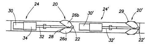
Referring to Fig. 2, the conveyance al~dllls 16 comprises an actuator 24 for
linearly displacing cam 20 which is pivotally mounted about a support frarne 22. Cam 2 0
consists of a strong, corrosion and wear resistant material, such as st~inlesc steel. Carn 2 0
comprises a pair of opposing .. "hc, ~ 26a and 26b having an arcuate surface and a
20 means for biasing an arcuate portion of the cam 20 into contact with a wall of the borehole
12. Preferably, the biasing means collll)lise a spring 28 placed between each ...~ ...l~. 26a
and 26b and the support frame 22. Spring 28 may consist of a torsion, extension, or
col,.p.~ssion spring. In an altemative embo~1im~nt of the invention, spring 28 is placed
between members 26a and 26b to bias the op~,osh~g ...~...hc,~ against each other and into
25 contact with a wall of borehole 12. Other means for biasing carn 20 against the borehole
12, including an electro-...rr~ l or hydraulic system, are within conternr! tion of this
invention. To further improve the contact between the cam 20 and the borehole 12, cam
CA 02245098 1998-08-17
~5.176
20 may have snlrlAed or particle .... ~ 29 fixably ~tt~rhr,~ to the arcuate surface. Studs
or particles 29 consist of a m~t~ l having high hardness and abrasio~ resicr~nreplu~llies~ such as tl-n~ct~n carbide.
Still lcf~ g to Fig. 2, actuator 24 is opc~vcly cc,....~-1ed to cam 20. Actuator24 comprises a motor 30 for rotating screw 32. The ~ . 24 may further comprise areduction gear box 34 ~licposcd ~t..~n motor 30 and screw 32. Altematively. actuator
24 may consist of other means for linearly ~ cam 20, including, but not limited
to, a hydraulic piston powered by a motor driven, hydraulic pump. When the motor 30 is
rotated ir~ one direction, screw 32 lincarly ~ es the cam 20 for vard and the arcuate
10 portion slidingly en~ges the borehole wall. When the motor 30 is rotated in the ~ osil~
direction, screw 32 pulls cam 20 ba~ ~d and locks the arcuate portion against the
borehole wall 12 and propelling the conv~.cc ~ uS and logging tool forward.
The conveyance apparanls 16 locks or slidingly ~n~rs the borehole wall for a
variable ~li,..". ~, borehole 12. figs. 3a- 3b depict the conveyance a~a~lu~ 16 within a
15 small and large ~ -. t ~ borehole 12. The contact angle~ ~, is between a point where an
arcuate por~ion of carn 20 COnl~ the borehole wall and a line drawn through the pivot
point 40 and peIpendic~ r to the borehole wall 12. The contact angle ruyuil~d to lock carn
20 against the borehole wall relates to the friction cl..u~.istics between cam 20 and the
borehole wall 12. The tangent of the contact angle, ~, must be smaller than the c~rr" i.,.~t
of friction between the carn and the borehole wall 12 so that ~r~ or 24 locks cam 20
against the borehole wall. To "~COIlll~ r a variable ~ borehole, the contact angle
remains cons~ .l as cam 20 pivots inwardly or outwardly to accol.l.lloA~te the borehole
m~ter.
In a plel~"cd c,..bod;.-.~ the conv_~.cc ~palduS 16 colllluliscs a pair of
actuators 24, 24' for linearly displacing cams 20, 20' which are pivotally mount~d about
a support frame 22, 22'. The action of sliding one cam 20 or 20' forward applies a
. CA 02245098 1998-08-17
''5. 1 76
reaction force against the conveyance d~ sldtUs 16 and logging tool 14 tending to move
the appdldlUS 16 and logging tool 14 baCkWdl-lS. Similarly, tension in the wireline 18
being pulled into a highly deviated or h~ .ol-l;.l section of the borehole 12 also tend to
move the a~dlus 16 and tool 14 backwiuds. The other cam 20~ or 20, which is locked
5 against the borehole wall 12 and not sliding forward, prevents backward movc.~ ,t of the
~J~JaldLUS 16 and logging tool 14.
Figs. 4a4c illustrate position, velocity, and force versus time for continuous
movement of the ~lc~ ,d conveyance ap~dlalus 16. In the home position, at t=0, the first
actuator 24 is fully e~t~n/~ for a ~lict~nre ap~lu ~"l,dlely equal to the length of screw 32.
10 Also, in the home position, the second a~u~,l 24' is fully .e~ d. In order to convey
the logging tool 14, a first motor 30 rotates in one direction and retracts screw 32 which
pulls cam 20 backward and locks the all uate portion against the borehole wall 12 and
propels the conveyance a~dldlus and logging tool forward. Sim~l~neously, a second
motor 30' rotates in one direction and screw 32' linearly displaces the cam 20' forward
15 and the arcuate portion slidingly eng~gçS the borehole wall 12. These actions are then
reversed such that the first motor 30 rotates in the o~,~osi~ direction and screw 32 linearly
displaces the cam 20 forward and the arcuate portion slidingly eng~geS the borehole wall
12 and simultaneously, the second motor 30' rotates in the c,p~osile direction and retracts
screw 32 which pulls cam 20' backw~d and locks the arcuate portion against the borehole
20 wall and propels the conveyance ap~.Lus and logging tool for vard. Figs. 4b-4c show
that the net motion of the conveyance al,pdl~us 16 and logging tool 14 are continuous and
the speed is inversely ~lopulLiona] to the pulling effort thereby reflecting the ability to
supply a limited amount of electrical power via the wireline 18.
In a second embo~im~nt of the invention, the pair of cams 20, 20' are first
''5 operated simult~nçoucly, then sequentially. The actuator 24, 24' for each cam 20, 20' is
cimlllt~neously activated to pull each cam 20, 20' backward thereby locking the arcuate
portions against the borehole wall 12 and propelling the conveyance a~yaldlus 16 and
~ CA 02245098 1998-08-17
''5.176
logging tool 14 forward. Next, the ~rtll~tors 24, 24' are sequentially activated to
dicpl~re each cam 20, 20' in a fo~ward direction. These steps are repeated until the
logging tool 14 is conveyed to a predetu.,llincd position.
In a third e..ho~ of the invention, one actuator 24 or 24' is
S leci~,~ed while the other a,.:tudt~r 24 or 24' ,elllail,s stationary. The moving actuator
24 or 24' is activated to pull the cam 20 or 20' backward thereby locking the arcuate
portion against the borehole wall 12 and propP1ling the conveyance ~JIJdldLUS 16 and
logging tool 14 forward. The moving actuator 24 or 24' is then activated to displace the
cam 20 or 20' in the forward direction. These steps are l~aled until the logging tool 14
10 is conveyed to apl~d~t~ ...;.-P~ position.
The foregoing ~IPsrrirtion of the ~ief~llcd and ~ltPm~tP embo~ nl~ of the present
invention have been ~l.,se.,t~d for ~UIlJ0~S of illustration and description. It is not in~rrlded
to be exhaustive or limit the invention to the preci~ form disclosed. Obviously, many
modifications and variations will be a~pd~lll to those slcilled in the art. The embo-i;...~ .-t~
15 were chosen and ~1P.ccribPd in order to best explain the prinrirlp~s of the invention and its
practical application thereby enabling others skilled in the art to und~ d the invention for
various emborlimPntc and with various mollifir~tions as are suited to the particular use
contemplated. It is int~nrlecl that the scope of the invention be defined by the accon,~a"ying
claims and their equivalents.