Note: Descriptions are shown in the official language in which they were submitted.
CA 02245241 2002-O1-14
A METHOD FOR PERFORMING A SOFT HANDOFF
CROSS REFERENCES
The present invention is related to U.S. Patent No. 6,073,021 which issued
on June 6, 2000, entitled "Robust CDMA Soft HandofP' by S. Kumar, W.Y. Kuo and
K. Rege.
FIELD OF THE INVENTION
to
The present invention relates to wireless communication systems and, in
particular, to performing a soft handoff in a wireless communication system.
BACKGROUND OF THE INVENTION
t5
Soft handoffs enable mobile-telephones to keep calls active without a user-
detectable disruption of communication as the mobile-telephones move from the
coverage area of one base station to that of another. Soft handoffs are
achieved by having
the mobile-telephone maintain simultaneous radio links with multiple base
stations - that
2o is, the mobile-telephone is in communication with at least two base
stations at the same
time. A mobile-telephone maintaining simultaneous radio links with multiple
base
stations is described herein as being in a soft handoff state. The success
rate of soft
handoffs depends on whether the mobile-telephone can successfully receive
handoff
direction messages, which are messages identifying a communication channel
assigned to
25 enable a base station not already in communication with the mobile-
telephone (i.e., base
station to be added to soft handoff state) to communicate with the mobile-
telephone. The
aforementioned success rate decreases significantly when the signals carrying
the handoff
direction messages have low signal-to-noise ratios at the mobile-telephone.
A wireless communication systeartiased on the well-known IS-95 Code
3o Division Multiple Access (CDMA) standard is described herein for purposes
of providing
2
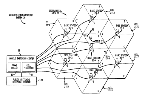
an understanding of soft handoffs. FIG. I illustrates an IS-95 based CDMA
wireless
communication system 20 that provides wireless communication services to a
geographical area 22. The geographical area 22 is divided into a plurality of
cells 24 j,
where j=1,...,7, which are further divided into a plurality of sectors A, B,
C. Each of the
cells 24 j has an associated base station 26 j, which provides wireless
communication
coverage to the cell. Each of the base stations 26 j is connected to a mobile
switching
center (MSC) 28, which is connected to a public switching telephone network
(PSTN) 29.
The MSC 28 includes a frame handler (FIB 30 and a call processor (CP) 32. The
frame
handler 30 is a device for selecting a copy of a message (among copies of the
same
message) with the best or acceptable signal quality, whereas the call
processor 32 is a
device for processing signaling messages, as will be described herein. Note
that each of
the base stations 26y may also include a frame handler and/or a call
processor.
Each of the base stations 26 j are operable to transmit a signal Z~~(t) to one
or more mobile-telephones. Typically, the signal Z~~(t) includes one or more
traffic
channel signals, a pilot channel signal and a paging channel signal. Traffic
channel
signals are coded voice/data signals transmitted on communication channels
referred to
herein as traffic channels. When the traffic channel signals are transmitted
from the base
station to the mobile-telephone, such signals are referred to herein as
forward (or
downlink) traffic channel signals. By contrast, when the traffic channel
signals are
2o transmitted from the mobile-telephone to the base station, such signals are
referred to
herein as reverse (or uplink) traffic channel signals. A pilot channel signal
is a pilot
signal transmitted on a communication channel referred to herein as a pilot
channel. The
pilot channel signal provides mobile-telephones with a phase reference for
coherent
demodulation of forward traffic channel signals and a means for signal
strength
comparisons between base stations for determining when to initiate a handoff.
A paging
channel signal is a paging signal transmitted on a communication channel
referred to
herein as a paging channel. A paging signal typically includes control
information, such
as a notification to a mobile-telephone when a call is to be received. The
manner in
which the pilot channel, paging channel, traffic channel, and other
communication
CA 02245241 1998-08-18
___
3
channels are defined depends on the specific implementation of the wireless
communication system.
In I~ 95, downlink communication channels (from the base station to the
mobile-telephone) are defined using a modulation scheme M over a specific
frequency
range, a pair of in-phase (I) and quadrature (Q) spreading sequences (i.e.,
pseudo-noise
sequences PNm and PN~~ with different phase offsets Pj referred to herein as
pseudo-
noise sequences PNm;j and PN~Q~ j, and a set of short sequences referred to
herein as
Walsh functions Wl. Each of the base stations 26 j in the wireless
communication system
20 uses the same modulation scheme M. Thus, the modulation scheme M identifies
a
1 o communication channel as belonging to a particular wireless communication.
Each of the
base stations 26 j uses the same pair of pseudo-noise sequences PNm and PN«
but
different phase offsets Pj. The phase offsets Pj are unique for each of the
base stations
26 j. Thus, the phase offset Pj identifies a communication channel as
belonging to a
particular base station 26 j. For example, PNm-1 and PN«-1 identifies the PNm
and PN«
t5 sequences and the phase offsets P, for base station 26-1. Each of the base
stations 26 j
uses a set of Walsh fimetions W; to identify particular communication channels
belonging to the base station. Thus, the base stations 26-j distinguishes
their
communication channels using the Walsh function WI.
FIG. 2 illustrates a manner in which communication channels are typically
2o defined for each base station in an IS-95 based CDMA wireless communication
system.
Each base station 26 j uses the same modulation scheme M to identify the
wireless
communication system, the same pair of PNm and PN« sequences but with
different
phase offsets Pj to identify. the base station (i.e., PNm j and PN« ~~, and
the same set of
Walsh fiuictions WI to identify a particular communication channel belonging
to the base
2s station. For example, suppose base station 26-4 uses Walsh function W,2 to
define one of
its forward traffic channels and base station 26-7 uses the same Walsh
function W,2 to
define one of its forward traffic channels. Although the same Walsh function
W,z is used
by different base stations 26-4 and 26-7, the forward traffic channels are
distinguishable
because each of the base stations 26-4 and 26-7 defines their respective
forward traffic
3o channels using PNm and PN« sequences with different phase offsets Pj, i.e.,
PNm-4 and
CA 02245241 1998-08-18
4
PN«-4 for base station 26-4 and PNm-9 and PN«-9 for base station 26-9.
Typically,
each of the base stations 26 j uses the same particular Walsh functions Wi to
define its
pilot channels, paging channels, and forward traffic channels. For example,
Walsh
functions Wo, W,, and W2,... Wn (along with the modulation scheme M and
spreading
sequences PNm j and PN~Q~ ~~ are used to define the pilot channel, paging
channel and
traffic channels at each of the base stations 26 j, respectively
FIG. 3 shows a simplified schematic of a base station 26 j processing n
input signals bi(t) for transmission to a multitude of mobile-telephones,
where "t"
represents time. The input signals bl~(t) are multiplied by the base station
26 j with Waish
1o functions Wi to produce output signals xt~(t). Each of the outputs xi(t) is
then multiplied
by a pair of pseudo-noise sequences PlVm j and PN« j to produce a pair of in-
phase and
quadrature chip streams x ~(t) and xi~Q~(t), respectively. These chip streams
xim(t) and
xi«(t) are then filtered (using a filter, such as a low bandpass filter) and
suitably
amplified (with Gain-i) before all of the in-phase aad quadrature chip streams
x ~(t) and
t 5 the xt«(t) are added together to form a combined in-phase output X~'~(t)
and a combined
quadrature output X«(t), respectively. The combined outputs Xm(t) and X«(t)
are then
used to respectively modulate in-phase carrier cos (w~t) and quadrature
carrier sin (cut),
where w~ represents the carrier frequency in radians per second. The resulting
signals are
added to get Z~~(t) and transmitted via an antenna by the base station 26 j.
2o For example, suppose input signal ba(t), input signal b,(t), and input
signals bz(t),...,bo(t) represent a pilot signal, a paging signal, and encoded
voice/data
signals, respectively. Then the pilot channel signal is the input signal bolt)
transmitted on
the pilot channel defined by the pair of spreading sequences PNm j and PN«;j,
the Walsh
function W~, and the carriers cos (c~~t) and sin (~~t). Likewise, the paging
channel signal
2s is the input signal b,(t) transmitted on the paging channel defined by the
pair of spreading
sequences PNm j and PN«y, the Walsh function W,, and the carriers cos (~~t)
and sin
(w~t), and the traffic channel signals are the input signals b2(t),...,bn(t)
transmitted on the
traffic channels defined by the pair of spreading sequences PNm j and PN« j,
the Walsh
functions WZ,...,Wa, and the carriers cos (w~t) and~in (cut).
CA 02245241 1998-08-18
5
The signal Z~~(t) transmitted from a base station 26y will typically travel
several paths to a mobile telephone - that is, a single signal Z~~(t) may
arrive as multiple
signals via different paths to the mobile-telephone. Such signals are referred
to herein as
mufti-path signals Z~,m(t), where m indicates a specific mufti-path for signal
Z~(t). IS-95
based mobile-telephones include RAKE receivers which use the mufti-path
environment
to improve the performance of the mobile-telephones. RAKE receivers include a
plurality of "fingers" (i.e., devices capable of demodulating received
signals) for
separately demodulating several mufti-path signals and a summer for combining
the
demodulated mufti-path signals to produce a net overall output, i.e., obtain a
single strong
to signal, as will be described herein.
Referring to FIG. 4, there is shown a schematic of a mobile-telephone 33
having an antenna 34 and a RAKE receiver 36, which includes a searcher 38, a
controller
40, a plurality of fingers 42-1, 2, 3, and a summer 43. Searchers,
controllers, fingers and
summers are well-known in the art. The antenna 34 receives a plurality of
mufti-path
t 5 signals Z~, m(t). The searcher 38, under the direction of the controller
40, scans for pilot
channel signals (being received via the mufti-path signals) transmitted from
base stations
in an active set and/or a neighbor set of base stations, as will be described
herein. The
active set includes base stations that are in communication with the mobile-
telephone.
Note that a base station and a mobile-telephone are in communication with each
other
2o when the base station listens to messages transmitted by the mobile-
telephone and vice-
versa. The active set typically includes a primary base station, i.e., base
station in control
of call processing for the mobile-telephone, and zero or more secondary base
stations,
i.e., base stations in communication with the mobile-telephone other than the
primary
base station The neighbor set includes base stations that are close and/or
adjacent to the
25 primary base station. The primary base station provides the mobile-
telephone with a list
indicating the base stations in the active set and the neighbor set.
In IS-95 based mobile telephones, the searcher 38 scans for the
aforementioned pilot channel signals within search windows corresponding to
the phase
offsets Pj associated with the base stations in the active set and/or neighbor
set, wherein
3o search windows are time intervals around the phase offsets P~ of the base
stations 26 j.
CA 02245241 1998-08-18
__ .
6
Recall that in IS-95 based CDMA wireless communication systems, each base
station 26-
j is typically configured to transmit signals, including the pilot signal,
using
communication channels defined by a unique phase offsets Pj. The phase offsets
Pj
allows the mobile-telephone to identify the base station from which a pilot
channel signal
was transmitted. For example, if a pilot channel signal was detected within a
search
window around a phase offset PZ, then the mobile-telephone may conclude that
the
corresponding mufti-path signal Zj,ri,(t) was transmitted by base station 26-
2.
Upon detecting the pilot channel signals (within the appropriate search
windows), the searcher 38 records the phases at which the pilot channel
signals were
1o actually detected and the corresponding signal strengths. The recorded
phases and signal
strengths are sent to the controller 40. The controller 40 uses this
information to instruct
the fingers 42-1, 2, 3 to lock on to particular mufti-path signals and extract
the desired
input signals bl(t). For example, suppose the base station 26-3 is
communicating with the
mobile-telephone 33 over a forward traffic channel defined using the Walsh
function Wz.
t 5 ~ In this scenario, the controller instructs the fingers 42-1, 2, 3 to
extract the coded
voice/data signal b2(t) from the three strongest mufti-path signals belonging
to the base
station 26-3, e.g., Z,~(t), Z3.s(t) and Z3,6(t). The outputs of the fingers 42-
1, 2, 3 are
combined by the summer 43 to produce a net overall gain for the coded
voice/data signal
bz(t), i.e., a single stronger signal bz(t).
2o FIG. 5 depicts a simplified schematic of a finger 42-k extracting the coded
voice/data signal bz(t) from a received mufti-path signal Zj,m(t). Note that
in order to
extract the coded voice/data signal bz(t) from the received mufti-path signal
Zj,"i(t), the
finger 42-k de-spreads the pilot channel signal and the appropriate traffic
channel signal
received via the mufti-path signal Zj, m(t), as will be described herein. The
front end of
25 the mobile telephone receiver comprises RF/IF circuitry (which precedes the
RAKE
receiver), which fi~equency shifts the mufti-path signal Zj,m(t) to base-band
using locally
generated carriers cos (~~t + ~) and sin (cut + ~), where ~ represents the
phase difference
between the carrier signal in a given mufti-path and its locally generated
replica at the
mobile telephone. The resulting base-band signals,ym(t) and y«(t) are then
filtered and
3o de-spread. Specifically, the filtered base-band signals ym(t) and y«(t) are
de-spread using
CA 02245241 1998-08-18
the Walsh function Wo and the spreading sequences PNm;j and PN«y to obtain de-
spread
pilot channel signals IIm and II«, where Ih=a~cos~+noise, IIt~= a~sin~+noise
and "a"
represents the amplitude of the pilot channel signal as a function of time.
Likewise, the
filtered base-band signals ym(t) and y<Q~(t) are de-spread using the Walsh
function WZ and
the spreading sequences PNm-j and P1V« j to obtain de-spread traffic channel
signals im
and t~Q~, where tin=b2 cosh+noise and t~Q~= b2 sinyr+noise.
Note that de-spreading the filtered base-band signals ym(t) and y~Q~(t) using
the spreading sequence PNm j and PN« j suppresses the interference due to the
transmission of signals by other base stations in the same wireless
communication
1o system, thereby enhancing the quality (at the mobile-receiver) of the
signals transmitted
from the desired base station 26y - that is, signals transmitted from the
desired base
station 26 j are made available. Further note that the use of Walsh functions
WI to
distinguish between communication channels minimizes interference due to the
transmission of signals by the same base station 26-j to other users in the
same coverage
t5 area.
Each of the de-spread pilot channel signals IIm and II« are typically
averaged over a few symbols (i.e., bits of convolutional coder output) to
suppress noise
(i.e., II m and II ~Q~ and then used to coherently demodulate the de-spread
traffic channel
signals im and i~Q~ to produce a demodulated signal.b'Z(t), where b'2(t}=II
mwm+
2o II ~Q~~z«. The demodulated signal b'2(t) at the output of a RAKE receiver
finger may be
delayed for a duration corresponding to the phase offset associated with the
corresponding mufti-path and then combined with the outputs of other fingers
(similarly
delayed to account for different path delays) to produce a single output with
an enhanced
signal-to-noise ratio - that is, the output of a RAKE receiver finger is time
aligned with
25 the outputs of other RAKE receiver fingers. Such combined output, generated
once every
coded symbol, is then de-interleaved and fed to a Viterbi decoder, not shown,
to extract
the desired voice/data signal.
One of the major benefits provided by a RAKE receiver is the ability to
simultaneously demodulate mufti-path signals from more than~one base station.
This
CA 02245241 1998-08-18
8
functionality allows the IS-95 based wireless communication system and mobile-
telephone to perform soft handoffs. Soft handoffs will now be described using
FIG. 6,
which is a simplified schematic of the above-described wireless communication
system
20 and base stations 26-4 and 26-3. Suppose mobile-telephone 33 is currently
within the
coverage area of the base station 26-4, i.e., cell 24-4, and listening to
(i.e., demodulating)
messages transmitted by the base station 26-4 over a first communication
channel C,
assigned to enable the base station 26-4 to communicate with the mobile-
telephone 33.
Note that the base station 26-4 is the primary base station. As the mobile-
telephone 33
moves near the coverage area of the base station 26-3, i.e., cell 24-3, a soft
handoff is
1o initiated. Note that the base station 26-3 is now a candidate base station,
i.e., a base
station to which a soft handoff is requested. Upon initiation of the soft
handoff, the
network connections necessary for the soft handoff are set up by the wireless
communication system, including assigning a second communication channel C3 to
enable the candidate base station 26-3 to communicate with the mobile-
telephone 33. A
copy of a handoff direction (HD) message indicating the identity of the
candidate base
station, as well as that of the second communication channel C3, is
transmitted (via the
signal Z~~(t)) to the mobile-telephone 33 by the primary base station 26-4
over the first
communication channel C4. Upon receipt of the HD message, the mobile-telephone
33 is
in a soft handoff state and will begin listening to messages transmitted on
the second
2o y communication channel Cain addition to messages transmitted on the first
communication
channel C4 - that is, the mobile-telephone 33 is maintaining simultaneous
radio links with
both of the base stations 26-4 and 26-3.
Typically, during the network connections set up for the soft handoff (and
before transmittal of the HD message). the mobile-telephone will move farther
from the
primary base station 26-4 and closer to the candidate base station 26-3. This
will cause
the signal-to-noise ratio of mufti-path signals Z~,m(t) containing the I~
message
(transmitted after completion of the network connections set up) to decrease
significantly
which, in turn, decreases the likelihood that the HD message will be
successfully received
by the mobile-telephone. Such failure prevents the.mobile-telephone from
attaining a
3o soft handoff state (since it would not know the identity of the second
communication
CA 02245241 1998-08-18
9
channel C3) - that is, the mobile-telephone 33 will not know to listen to
messages
transmitted from the base station 26-3 on the second communication channel. As
a result
of not attaining the soft handoff state, the mobile-telephone 33 will be
unable to keep the
call active as the mobile-telephone 33 moves farther away from the primary
base station
26-4 and towards the candidate base station 26-3 - that is, the mobile-
telephone may lose
the call. This is one major reason for decreasing soft handoff success rate.
Accordingly,
there exists a need to increase the success rate of soft handoffs.
SLIMMARY OF THE INVENTION
The present invention increases the success rate of soft handoffs by
enhancing the ability of a mobile-telephone to receive a handoff direction
message that
identifies the traffic channel being assigned to enable a candidate base
station to
communicate with the mobile-telephone. Specifically, the aforementioned
ability of the
t 5 mobile-telephone is enhanced by using the candidate base station to
transmit the handoff
direction message on a communication channel belonging to the candidate base
station
and being listened to by the mobile-telephone. In situations where signals
transmitted
from active set base stations have a low signal-to-noise ratio at the mobile-
telephone,
signals transmitted from the candidate base station may have a higher signal-
to-noise
2o ratio at the mobile-telephone. In these situations, the transmission of the
HD messages
from the candidate base station increases the likelihood that a copy of the
handoff
direction message will be successfully received by the mobile-telephone,
thereby
enhancing the success rate of soft handoffs. In one embodiment, the mobile-
telephone
will use at least one of its RAKE receiver fingers to listen to the paging
channel of the
25 candidate base station when a soft handoff is initiated. At the same time,
the candidate
base station transmits on its paging channel a copy of the handoff direction
message
along with an identifier indicating that the handoff direction message is
intended for the
mobile-telephone. Upon receiving the copy of the handoff direction message
(via the
candidate base station's paging channel), the mQhiJ,e-telephone will know to
listen to the
3o traffic channel identified in the handoff direction message. In another
embodiment, base
CA 02245241 1998-08-18
10
stations in as active set of base stations also transmit copies of the handoff
direction
message on forward traffc channels already being used by each of the base
stations in the
active set to communicate with the mobile-telephone.
BRIEF DESCRIPTION OF THE DRAWINGS
The features, aspects, and advantages of the present invention will become
better
understood with regard to the following description, appended claims, and
accompanying
drawings where:
to FIG. 1 depicts a wireless communication system;
FIG. 2 depicts how communication channels are typically defined in an IS-95
based CDMA wireless communication system;
FIG. 3 depicts a simplified schematic of a base station processing input
signals for
transmission to a multitude of mobile-telephones;
t 5 FIG. 4 depicts a simplified schematic of a mobile-telephone having an
antenna
and a RAKE receiver;
FIG. 5 depicts a simplified schematic of a finger extracting the coded voice
signal
from a received mufti-path signal;
FIG. 6 depicts a simplified schematic of base stations 26-3 and 26-4 of FIG. 1
2o processing a soft handoff;
FIG. 7 depicts a flowchart illustrating a soft handoff from the perspectives
of a
mobile-telephone; and
FIG. 8 depicts a flowchart illustrating a soft handoff from the perspectives
of a
wireless communication system.
DETAILED DESCRIPTION
For purposes of discussion, the present invention will be described herein
with respect to the above-described wireless communication system and mobile-
3o telephone employing Code Division Multiple Access (CDMA) techniques based
on the
CA 02245241 1998-08-18
11
well-known IS-95 wireless communication standards. The present invention can
be
equally applicable to wireless communication systems employing other CDMA
techniques (e.g. ones based on the ANSI J 008 standard) or those employing
other types
of multiple access techniques, such as time division multiple access (TDMA)
and
frequency division multiple access.
As mentioned earlier, one of the major benefits provided by a RAKE
receiver is the ability to simultaneously demodulate mufti-path signals from
more than
one base station. This functionality allows the IS-95 based wireless
communication
system and mobile-telephone to perform soft handoffs. The present invention
extends
1o this functionality to enhance soft handoffs. Specifically, the present
invention dedicates
one of the mobile-telephone's RAKE receiver fingers to listen to a
communication
channel belonging to the candidate base station for some time interval
corresponding to
the possible arrival of copies of a HD message. During or immediately the ,
aforementioned time interval, the candidate base station (and/or other base
stations) will
15 ~ transmit the copies of the HD message (via signals Z~~(t)).
FIGS. 7 and 8 depict flowcharts 60 anti '70 illustrating a soft handoff from
the perspectives of a mobile-telephone and a wireless communication system,
respectively, in accordance with one embodiment of the present invention. In
step 600, a
mobile-telephone is engaged in a call. At this time, the fingers of the mobile-
telephone
2o are dedicated to extracting a coded voice/data signal bq(t), where
q=2,...,n, from one or
more mufti-path signals Z~, m(t) transmitted by base stations in the active
set - that is, the
fingers are listening to one or more of the active base stations' assigned
forward traffic
channels, i.e., forward traffic channels assigned to enable the active set
base stations to
communicate with the mobile-telephone. In step 605, a soft handoff is
initiated by the
z5 mobile-telephone when the mobile-telephone detects a pilot channel signal
from a base
station in the neighbor set with a strength exceeding a threshold T ADD. This
base
station is now a candidate base station.
In step 610, the mobile-telephone transmits a pilot strength measurement
(PSM) .message indicating the detection of the candidate base station. The PSM
message
3o is transmitted in-band on a reverse traffic channel assigned to enable the
mobile-
CA 02245241 1998-08-18
12
telephone to communicate with the base stations in the active set. In other
words, the
mobile-telephone transmits a PSM message on a reverse traffic channel which is
being
listened to by the base stations in the active set. In step 615, the mobile-
telephone sets a
timer to expire after a time interval T Listen and dedicates a subset of
forgers (for the
time interval T Listen or part thereof) to listen to the paging channel
belonging to the
candidate base station. Such dedicated subset of fingers is hereinafter
referred to as the
paging channel fingers. Recall that a communication channel, such as the
paging
channel, is described herein as belonging to a base station 26 ; j if the
communication
channel is defined using the PNm and PN« sequences with the phase offset Pj of
the base
to station 26 j.
Note that the fingers not dedicated to the paging channel, i.e., traffic
channel fingers, remain dedicated to listening to the active set base
stations' assigned
forward traffic channels. Further note that the present invention is not
limited to
receiving (or transmitting) the HD message over the candidate base station's
paging
15 channel. Such message may be received (or transmitted) over any
communication
channel belonging to the candidate base station so long as the mobile-
telephone knows or
can ascertain the identity of such communication channel. In other words, the
mobile-
telephone should have a priori knowledge of the communication channel over
which the
candidate base station will transmit the HD message (so that a subset of
fingers may be
2o dedicated to listen to that communication channel). The paging channel is
one possibility
In step 620, the mobile-telephone checks if one or more copies of the HD
message (intended for the mobile-telephone) was received over the candidate
base
station's paging channel and/or one of the active set base stations' assigned
forward
traffic channels. An identifier indicating the particular mobile-telephone to
which the HD
25 message is intended, such as a mobile-telephone identification number
(MIN), is also
transmitted over the candidate base station's paging channel along with the
copy of the
handoff direction message. The identifier allows the mobile-telephone to
determine
whether to process the associated HD message. If no copy of the HD message was
received, the mobile-telephone checks whether the timer has expired, i.e.,
time interval
3o T Listen has elapsed, in step 625. If the timer expired, then the mobile-
telephone re-
CA 02245241 1998-08-18
__ ____ ______ _____ _ ._
13
dedicates the paging channel forgers to listen to one of the active set base
stations'
assigned forward traffic channels, in step 630. If the timer did not expire,
then the
mobile-telephone repeats step 620.
If a copy of the HD message is received over the candidate base station's
paging channel or one or more of the active set base stations' assigned
traffic channel,
then the mobile-telephone re-dedicates the paging channel fingers to
demodulate the
active set base stations' assigned traffic channel and adds the candidate base
station to its
active set of base stations (after extracting the HD message), in step 635 -
that is, the
candidate base station becomes a secondary base station to which the mobile-
telephone
1 o will listen (in addition to all of the other base stations which were
already in the mobile-
telephone's active set). Alternately, the candidate base station can replace
the primary
base station, thus becoming the primary base station. Upon completion of step
635, the
mobile-telephone is in a soft handoff state with the candidate base station as
well as those
that are already in its active set.
15 Note that the output of the paging channel forgers is not combined with the
output of the traffic channel forgers. Message level selection diversity is
expanded to
include messages transmitted by the candidate base station over its.paging
channel.
Specifically, message level selection diversity is employed to enable the
mobile-
telephone to receive the HD message if either the candidate base station or
the active set
20 - base stations are able to deliver the HD message at a reasonable signal
to noise ratio.
Meanwhile, the following occurs at the wireless communication system
during the time interval T Listen. In step 700, the active set base stations
that receive the
PSM message (transmitted in step 610) will demodulate their PSM message and
send the
demodulated PSM message to a common frame handler where, is step 705, the PSM
2s message with the best or acceptable, e.g., over a threshold, signal quality
is selected. In
step 710, the selected PSM message is routed to a call processor (CP) where,
in step 715,
the PSM message is used by the CP to set up the network connections necessary
for
performing the soft handoff.
Network connections setup (for sQft,handoffs) involves messaging or
3o interaction between the CP, the candidate base station, and the network
infrastructure of
CA 02245241 1998-08-18
14
the wireless communication system. Specifically, in step 715, the CP sends a
message to
the candidate base station requesting a new forward traffic channel be
assigned to enable
the candidate base station to communicate with the mobile-telephone, and
informing the
candidate base station of the reverse traffic channel being used by the mobile-
telephone
(so the candidate base station knows what reverse traffic channel to which it
should
listen). At the same time, the CP interacts with the network infrastructure to
set up a link
or a connection between the candidate base station and the frame handler. This
enables
proper routing of messages (to and from the mobile-telephone) between the
candidate
base station and the frame handler.
to Upon completing the network connections setup, in step 720, the CP sends
copies of a handoff direction (HD) message to the active set base stations and
the
candidate base station. The HD message indicates the identity of the candidate
base
station and new forward traffic channel being assigned to enable the candidate
base
station to communicate with the mobile-telephone. In step 725, the active set
base
t 5 stations and the candidate base station transmit the copies of the HD
message to the
mobile-telephone. Specifically, the active set base stations synchronously
transmit the
copies of the HD message using the forward traffic channels assigned to enable
them to
communicate with the mobile-telephone, and the candidate base station (non-
synchronously or synchronously) transmits the HD message with a mobile-
telephone
2o identification number (N1II~ to the mobile-telephone using the paging
channel of the
candidate base station - that is, all of the base stations in the active set
transmits the HD
message at the same time, and the candidate base station transmits the HD
message at a
different time or the same time. Recall that the MIN identifies the mobile-
telephone as
the intended recipient of the handoff direction message.
25 Transmitting a copy of the HD message from the candidate base station
will increase the likelihood of successful receipt of the HD at the mobile-
telephone. For
example, referring back to FIG. 6, suppose the base station 26-4 is one of the
active set
base stations and the base station 26-3 is the candidate base station. During
the setting up
of the soft handoff network connections (i.e., step,.ZlS), the mobile-
telephone 33 moves
3o from position Rl to position R2. At position R2 (as opposed to position
Rl), the signal-
CA 02245241 1998-08-18
15
to-noise ratio for signals transmitted by the active set base station 26-4
decreases and the
signal-to-noise ratio for signals transmitted by the candidate base station 26-
3 increases.
In this situation, it is more likely that a HD message transmitted from the
candidate base
station 26-3 will be correctly received than a HD message transmitted from the
active set
base station 26-4.
In step 730, the candidate base station will begin to carry the call over the
newly assigned forward traffic channel upon completion of the network
connections
setup - that is, the candidate base station will carry copies of forward link
transmissions
on the newly assigned forward traffic channel, and demodulate the mobile-
telephone's
t o reverse link transmissions (and pass them to the frame handler).
Although the present invention has been described in considerable detail
with reference to certain embodiments, other versions are possible. The
present invention
can be equally applicable to "softer handoffs" and hard handoffs. Therefore,
the spirit
and scope of the present invention should not be limited to the description of
the
t 5 embodiments contained herein.
CA 02245241 1998-08-18