Note: Descriptions are shown in the official language in which they were submitted.
CA 0224~28~ 1998-08-10
~ IMPROVED BRAKING SYSTEM FOR A VEHICLE
FIFI.D OF THE INVENTION
This invention relates to an improved braking system of,
for example, trucks, trailers and the like. In one embodiment, the
braking system incorporates a means for greasing the pivoting surfaces
10 of an air brake system. In another embodiment, the braking system also
includes an air brake adjustment indicator.
BACKGROUND OF THE INVENTION
Braking systems for vehicles (eg. trucks, trailers and the
15 like) typically utilize an air brake system having a pressure chamber, a
push rod extending longitudinally outwards from the pressure
chamber, a brake arm and a clevis pin for pivotally mounting the brake
arm to the push rod. When the brake pedal is depressed, air pressure
increases in the pressure chamber. As the air pressure increases, a
20 diaphragm contained in the pressure chamber deforms and exerts an
outward pressure on the push rod. The deforrnation of the diaphragm
causes the push rod to move outwardly from the pressure chamber,
actuating the braking mechanism. When air brake systems are properly
adjusted, the push rod extends from a first position (in which the
25 brakes are not engaged) to a second position (in which the brakes are
fully engaged). Over time, as the brakes are repeatedly applied, the
distance travelled by the push rod may increase requiring the brake
system to be adjusted.
Some braking systems include slack adjusters. The slack
30 adjuster is used to take up the excess clearance, i.e. the slack, caused by
lining and drum wear. However, it is still important to regularly
monitor the distance travelled by the push rod since this provides
information regarding the degree of wear of the braking systems.
Further, some jurisdictions require the operator of a truck to inspect
35 the adjustment of the braking system before the vehicle's first trip each
CA 0224~28~ 1998-08-10
- 2 -
day.
Various devices have been developed to assist in
monitoring the adjustment of brake systems.
United States Patent No. 4,279,214 (Thorn) discloses a brake
5 ware indicator comprising a sleeve that loosely fits over the push rod
of the pneumatic actuator of the brakes. The sleeve has an outside
diameter permitting it to be received on the aperture of the actuator
housing which slidably receives the push rod.
United States Patent No. 4,776,438 (Shandelmeier) discloses
10 an air brake adjustment indicator comprising a bracket having an
elongated body portion. A base plate is provided at one end for
mounting on the vehicle. A pointer is adjustably mounted on the
bracket at a predetermined distance from the clevis pin of the brake
system in a direction opposite the air chamber when the clevis pin is in
15 its normal, rest position.
United States Patent No. 4,879,964 (Emerson, Jr.) discloses
an adjustment marker comprising a chain of predetermined length
which is attached to the push rod. A snap is attached to one end of the
chain and a clamp is attached to the other end. An indicator flag is
20 attached to the chain near the snap so that, when the push rod travels
further than the predetermined length, the snap will release and drop
the indicator flag downwardly so as to be visible to the operator of the
vehicle.
United States Patent No. 5,244,061 (Hoyt et al No. 1)
25 discloses an air brake stroke length gauge comprising a stroke length
indicator and a reference marker. The stroke length indicator is
mounted on the push rod to move therewith. The reference marker is
fixedly attached to the air brake system adjacent to the push rod at a
distance which corresponds to the appropriate stroke length for the
30 brake system when properly adjusted.
United States Patent Nos. 5,320,198 (Hoyt et al No. 2) and
5,441,128 (Hoyt) disclose air brake stroke length adjustment gauges
; CA 0224~28~ 1998-08-10
-3-
utilizing markers provided on the slack adjuster to indicate brake wear.
One disadvantage of some of these devices is that some
portions of the indicator devices are subject to movement or may fall
off with use. For example, when a vehicle is being driven, the frame of
5 the vehicle and parts attached thereto (eg. the brake and the adjustment
gauge) undergo substantial vibrations. This could result in the position
of the reference marker and the stroke length indicator of Hoyt et al
moving and accordingly providing a false reading.
A further disadvantage of some of these devices is that a
10 warning is only provided when the push rod extends too far. For
example, the device of Emerson, Jr. only provides a warning when the
snap releases and the flag falls.
A further disadvantage of some of the devices is that it is
difficult for the operator to properly read the adjustment gauge.
15 Adjustment gauges are mounted near the push rod. If the operator
reads the gauge from an angle, then a false reading may be obtained. In
addition, some of these devices are not readily adjustable and
substantial time may be required to properly mount and set the gauges.
A final disadvantage of some of these devices is that over
20 the lifetime of the braking system, the clevis pin tends to seize in either
the yokes of the pushrod or the yoke of the slack adjuster or the brake
arm. If the truck is not in use, then the clevis pin may become seized
in the slack adjuster/brake arm and/or the yoke. If the truck is in
regular use, then continual applications of the brake will assist in
25 preventing the clevis pin becoming seized in then slack adjuster/brake
arm. However, the clevis pin may still become seized in the yoke.
SUMMARY OF THE PRESENT INVENTION
In accordance with the instant invention there is provided,
30 in a braking system for a vehicle including a pressure chamber, a
pushrod extending longitudinally outwards from the pressure chamber
and movable when correctly adjusted between first and second
CA 0224~28~ 1998-08-10
-4-
positions, a brake assembly for braking the vehicle and a pivot member
for pivotally mounting a portion of the brake assembly to a portion of
the pushrod, an improvement comprising:
(a) an indicator adapted to be mounted for longitudinal
movement with the pushrod;
(b) a support member having a Hrst portion and a second
portion, the first portion adapted to be mounted to the
vehicle, the support member conHgured to position the
second portion opposite to the indicator;
(c) a first reference member positionable on the second
portion of the support member for marking the first
position and a second referellce member positionable on
the second portion of the support member for marking the
second position;
(d) a locating member for positioning the first reference
member in a preselected position relative to the second
refere.,ce member;
(e) at least one locking member for releasably mounting the
first and second reference members on the second portion,
the locking member moveable between a first position in
which the first and second reference members are fixed in
position on the second portion of the support member and
a second position in which the first and second reference
members are moveable as a unit with respect to the
indicator on the second portion; and,
(fl the pivot member comprising a cievis pin having an
outer surface, first and second ends and at least one
lubrication channel for providing grease to the outer
surface adjacent at least one the portion of the brake
assembly pivotally mounted on the clevis pin and the
portion of the pushrod pivotally mounted on the clevis
pin.
CA 0224~28~ 1998-08-10
--5 --
In accordance with the instant invention there is also
provided, in a braking system for a vehicle including a pressure
chamber, a pushrod extending longitudinally outwards from the
pressure chamber and movable when correctly adjusted between first
and second positions, a brake assembly for braking the vehicle and a
pivot member for pivotally mounting a portion of the brake assembly
to a portion of the pushrod, an improvement comprising:
(a) an indicator adapted to be mounted for longitudinal
movement with the pushrod;
(b) a re~erellce member for marking one of the first and the
second position, the reference member mounted in an
opposed position to the indicator; and,
(c) the pivot member comprising a clevis pin having an
outer surface, first and second ends and at least one
lubrication channel for providing grease to the outer
surface adjacent at least one the portion of the brake
assembly pivotally mounted on the clevis pin and the
portion of the pushrod pivotally mounted on the clevis
pin.
In one embodiment, the indicator is mounted on one end
of the clevis pin. The clevis pin may have a grease nipple adapted for
receiving lubricant from an automatic greasing system for the vehicle.
In a further embodiment, the clevis pin comprises a
substantially cylindrical elongate body having a bore adapted to receive
a grease nipple and, a lubrication channel network extending from the
bore to the outer surface of the clevis pin.
In an alternate embodiment, the clevis pin comprises a
substantially cylindrical elongate body having a bore adapted to receive
a grease nipple and extending inwardly from the outer surface in the
region of one of the ends and, a lubrication channel network which
extends through the body, one end of which is positioned under, and
which communicates with, the bore and at least one other end of
CA 0224~28~ 1998-08-10
-6-
which communicates with the outer surface at a point offset from the
bore in the direction of the other end.
In accordance with the instant invention there is also
provided, in a braking system for a vehicle including a pressure
chamber, a pushrod extending longitudinally outwards from the
pressure chamber and movable when correctly adjusted between first
and second positions, a brake assembly for braking the vehicle and a
- pivot member for pivotally mounting a portion of the brake assembly
to a portion of the pushrod, the pivot member and the portions of the
brake assembly and the pushrod defining pivoting surfaces, an
improvement comprising a clevis pin having:
(a) a substantially cylindrical elongate body having an outer
surface and first and second ends;
(b) a bore adapted to receive a grease nipple and extending
inwardly from an outer portion of the clevis pin in the
region of the first end; and,
(c) a lubrication channel network which extends through
the body, one end of which communicates with the bore
and at least one other end of which communicates with the
outer surface at a point offset from the bore in the direction
of the second end.
In one embodiment the grease nipple is adapted for
receiving lubricant from an automatic greasing system for the vehicle,
whereby on application of the automatic greasing system for the
vehicle, the pivoting surfaces are lubricated.
- In another embodiment the lubrication channel network
comprises a first lubricant channel having a first end and a second end
and extending axially within the body, the first lubricant channel
communicating with the bore; and, a second lubricant channel having
a first end and a second end and extending transversely through the
cylindrical body, the second lubricant channel intersecting the first
lubricant channel to be in communication therewith, at least one of the
CA 0224~28~ 1998-08-10
-7-
first and second ends of the second lubricant channel positioned
adjacent the outer surface of the clevis pin to communicate therewith.
In another embodiment the first lubrication channel
extends from the first end of the clevis pin towards the second end and
5 the bore for receiving the grease nipple is positioned in the first end.
In another embodiment the first lubrication channel
extends from the first end of the clevis pin towards the ~cond end, the
bore extends from the outer surface of the clevis pin to intersect the
first lubricant channel and the first end of the first lubrication channel
10 is provided with a lubricant plug which securely plugs the first end of
the first lubrication channel.
In another embodiment the elongate body of the clevis pin
also comprises an enlarged portion which is sized to accommodate the
bore which is positioned therein and extends from the surface of the
15 enlarged portion.
In another embodiment the elongate body has a retention
cross-bore which is adapted to receive an axial retention member
extends through and transversely to the axis of the cylindrical body in
the region of one of the ends, the retention cross-bore having first and
20 second ends which communicate with the outer surface. The retention
cross-bore may be positioned on the second end of the clevis pin. The
axial retention member may be a cotter pin.
One advantage of the instant adjustment indicator is that it
provides a gauge for measuring not only the outward travel of the
25 push rod but also the inward travel of the push rod. If the push rod
extends too far outwardly, then this provides an indication, for
example, that the brake pads are worn and need replacement.
Alternately, if the push rod does not fully retract, then this provides an
indication, for example, that the cam, the slack adjuster or the
30 operating shaft is broken and/or worn or that there is a malfunction in
the air chamber.
A further advantage of the instant adjustment indicator is
CA 0224~28~ 1998-08-10
-8-
that the indicator and the first or second reference members ~referably
interact when the indicator extends past a first or second reference
members. This provides a positive visual signal, independent upon
the angle from which the adjustment gauge is observed, that the brake
~ysteln requires adjustment.
A further advantage of the instant invention is that it
provides a greaseable clevis pin for operatively and pivotally
connecting the yokes of a pushrod to the yoke of a brake arm of a
vehicle braking system such that the contact surfaces may be provided
with lubricant.
A further advantage of the present invention is that it
provides a greaseable clevis pin for operatively and pivotally
connecting the yokes of a pushrod to the yoke of a brake arm of a
vehicle braking system and for receiving lubricant from an automatic
greasing system for a truck, such that the contact surfaces are provided
with lubricant supplied by the automatic greasing system.
DESCRIPTION OF THE DRAWING
These and other features of the instant invention will be
more fully understood in reference with the following description of a
preferred embodiment of the invention in which:
Figure 1 is a partial cross-section of an air brake system
having a brake adjustment indicator pursuant to the instant invention
mounted thereon and showing a properly adjusted air brake system
with the brake engaged;
Figure 2 shows the air brake system of Figure 1 showing a
properly adjusted air brake system with the brake disengaged;
Figure 3 shows the air brake system of Figure 1 in which the
air brake system requires adjustment;
Figure 4 is a perspective view of a support means according
to the instant invention;
Figure 5 is an exploded view of a support means according
- CA 0224~28~ 1998-08-10
', _9_
to the instant invention and an indicator means of the instant
nvention;
Figure 6 is a perspective view of a brake adjustment
indicator according to the instant invention mounted on a front brake
of a vehicle;
Figure 7 is a perspective view of a brake adjustment
indicator according to the instant invention mounted on a rear brake
of a vehicle;
Figure 8 is a perspective view of a brake adjustment
indicator according to the instant invention when mounted on a
trailer;
Figure 9 is an exploded view of a clevis pin according to the
instant invention;
Figure 10 is a cross-sectional view along the line 9-9 of the
clevis pin of Figure 9;
Figure 11 is a perspective view of the clevis pin of Figure 9
when installed within the brake adjustment indicator system of Figure
1 and when attached to an automatic lubrication syslem for a vehicle.
DESCRI~IION OF PREFERRED EMBODIMENT
As shown in Figures 1 - 3, braking systems for vehicles (eg.
trucks, trailers and the like), generally designated by reference number
10, comprise a pressure chamber 12 having a diaphragm 14, a push rod
16 and a brake arm (which may be or which may include a slack
adjuster) 18. Push rod 16 may abut against diaphragm 14 and move
longitudinally into and out of pressure chamber 12 with the respective
contraction or expansion of diaphragm 14. A brake arm or slack
adjuster 18 is pivotally mounted by pivot means to push rod 16 about
axis 20. Preferably, the pivot means is a clevis pin 64 (see Figure 9).
Brake arm 18 is connected to the braking assembly of a vehicle so that,
upon movement of push rod 16, brake arm 18 causes the brake to
engage or disengage, depending upon the direction of travel of push
CA 0224~28~ 1998-08-10
- 10-
rod 16. Pressure chamber 12 may be affixed to the vehicle by any
means known in the art. As shown in Figures 1 - 3, pressure chamber
12 may be affixed to vehicle frame 22 by means of mounting bolts 24.
The brake adjustment indicator according to the instant
invention comprises bracket 30, first reference pointer 32, second
reference pointer 34 and indicator 36. Indicator 36 is adapted to be
mounted for longitudinal movement with push rod 16. Preferably,
indicator 36 is adapted to be mounted to clevis pin 64. Indicator 36 may
therefore be adapted to be mounted on clevis pin 64 or indicator 36 may
be formed integrally with clevis pin 64.
Bracket 30 is a support member which is adapted to be
mounted to the vehicle. As shown in Figure 4, the bracket has a first
portion 38 which is adapted to mount bracket 30 on the vehicle and the
second portion 40 which is adapted to receive first and second reference
pointers 32 and 34.
Bracket 30 may be mounted on the vehicle by any means
known in the art. As shown in Figure 4, first portion 38 may have an
opening 42 which is adapted to be mounted on bolt 24 as shown in
Figures 1 - 3. In order to install bracket 30, nut 44 is removed from bolt
24, bracket 30 is placed so that bolt 24 extends through opening 42 and
nut 44 is reapplied to bolt 24 to fix bracket 30 in position. Preferably,
opening 42 is a longitudinally extending opening so that bracket 30 may
be fixed to vehicle frame 22 in a variety of positions. Alternately, first
portion 38 may have a plurality of openings provided therein, each of
which are adapted to receive bolt 24.
Second portion 40 is adapted to receive reference pointers
32 and 34. Bracket 30 is configured so that reference pointers 32 and 34
are positioned opposite indicator 36. Bracket 30 may be a member
which extends longitudinally from bolt 24 to a position opposite clevis
pin 64. As shown in Figures 4 and 6 - 8, the exact configuration of
bracket 30 may be varied, depending on the braking system which is
used and the position at which bracket 30 is affixed to the vehicle, so
CA 0224~28~ 1998-08-10
-
- 11 -
that reference pointers 32 and 34 may mark the correctly adjusted
position of push rod 16.
When correctly adjusted, the push rod of the braking
sysLem typically moves between a first inner position and a second
5 outer position. For example, if indicator 36 is mounted on clevis pin 64
as shown in Figures 1 - 3, then, when the brakes are correctly adjusted,
indicator 36 moves longitudinally with push rod 16 to a first particular
distance from pressure chamber 12 when the brakes are applied and to
a second particular distance from pressure chamber 12 when the brakes
10 are released. The actual distance which is travelled and the inner and
outer positions will depend upon the braking system which is used.
Each manufacturer generally indicates the correct displacement of push
rod 16 when it is properly adjusted.
Second portion 40 of bracket 30 is positioned opposite
15 indicator 36 so that, when correctly adjusted, indicator 36 will travel
with push rod 16 between first and second rererence pointers 32 and 34.
Bracket 30 is configured to so position second portion 40. Referring to
Figures 1 - 3, referellce pointer 32 extends longitudinally in the plane
passing transversely through push rod 16 at the correctly adjusted
20 inner position and reference pointer 34 extends longitudinally in the
plane passing transversely through push rod 16 at the correctly
adjusted outer position.
If indicator 36 extends outwardly past reference pointer 34,
as shown in Figure 3, this would indicate to the operator of the vehicle
25 that there may be excessive wear on the brakes and that, for example,
the brake pads may need replacement. If, on the other hand, the
indicator travels so that it does not travel to a position adjacent
reference pointer 32, then this would indicate to the operator of the
vehicle that the cam, the slack adjuster or the operating shaft of the
30 braking system may be worn or broken, that there is a malfunction in
pressure chamber 12 or that other parts of the braking system require
maintenance. Accordingly, one advantage of the instant invention is
CA 0224~28~ 1998-08-10
- 12-
that it provides a reference mark for both the outward position of push
rod 16 when it is correctly adjusted and the inward position of travel of
push rod 16 when it is operating properly.
Referring to Figures 4 and 5, the construction of reference
pointers 32 and 34 will be discussed. Reference pointers 32 and 34 are
mounted on second portion 40 of bracket 30 a preselected distance
apart. Further, reference pointers 32 and 34 are mounted for
simultaneous movement as a unit on second portion 40. To this end,
second portion 40 may have a longitudinally extending opening 50.
Bracket 30 is configured so that opening 50 extends longitudinally,
parallel to the direction of travel of push rod 16. A spacer, comprising
plate 52 having openings 54, is provided. Reference pointers 32 and 34
are slidable mounted on second portion 40 by bolts 56 which extend
through longitudinally extending opening 50, through an opening 54
and into one of the referellce pointers. Locking means is also provided
to releasably secure pointers 32 and 34 in position on second portion 40.
Accordingly, lock washers 58 and nut 60 may be provided.
When assembled, distal end 62 of bolts 56 abuts against
second portion 40. Bolts 56 pass through longitudinally extending
opening 50, opening 54, lock washer 58 and nut 60 into one of refele,lce
pointers 32 and 34. By tightening nut 60 on bolt 56, plate 52, and
accordingly reference pointers 32 and 34, are releasably fixed in position
on bracket 30.
Openings 54 are provided a pre-selected distance apart. The
pre-selected distance depends upon the permitted travel distance of
push rod 16 when it is correctly adjusted. As the permitted distance of
travel of push rod 16 varies, a different plate 52 having openings 54
spaced a different preselected distance apart may be utilized.
Accordingly, another advantage of the instant invention is that bracket
30 may be adapted for different braking systems by switching to a
different plate 52. It will also be appreciated by those skilled in the art
that plate 52 may have a plurality of openings and that the plate may be
CA 0224~28~ 1998-08-10
- 13-
appropriately marked to indicate those openings which are to be used
with different braking systems. Alternately, a ruler or the like may be
provided on plate 52 with the plurality of openings so that an
appropriate pair of holes 54 may be selected depending upon the
5 distance which push rod 16 may travel.
As also shown in Figure 5, indicator 36 may comprise a
hollow cylindrical member having an opening 66 which is adapted to
fit onto end 68 of clevis pin 64. Alternately, it will be appreciated by
those skilled in the art that clevis pin 64 may be integrally formed
10 with indicator 36.
Preferably, as shown in Figure 2, indicator 36 extends
between reference pointers 32 and 34 so as to contact referel.ce pointer
32 when push rod 16 is working properly and is fully retracted and so as
to contact reference pointer 34 as push rod 16 travels outside its
15 correctly adjusted range. Accordingly, as shown in Figure 2, distal end
70 of indicator 36 may be positioned nearer bracket 30 than distal end 72
of pointers 32 and 34. Alternately, as shown in Figures 7 and 8,
reference pointers 32 and 34 may be positioned perpendicular to
indicator 36. In any event, it is preferred that indicator 36 is sufficiently
20 long so as to contact reference pointers 32 and 34 as discussed above.
Preferably, indicator 36 and/or re~rence pointers 32 and 34
are flexible so that, if indicator 36 contacts reference pointer 34, one of
reference pointer 34 and the indicator (or both) will deform to permit
indicator 36 to travel past the reference pointer. Accordingly, as shown
25 in dotted outline in Figure 3, as indicator 36' contacts reference pointer
34, indicator 36' deforms as it travels past reference pointer 32. Once
past reference pointer 32, indicator 36 will preferably return to its
original shape. Therefore, it is preferred that indicator 36 and/or
reference pointers 32 and 34 are made of a resilient material such as
30 rubber, neoprene or the like.
In order to increase the visibility of indicator 36 and
reference pointers 32 and 34, these members are preferably of a colour
CA 0224~28~ 1998-08-10
- 14-
which contrasts with the colour of the braking system. Preferably, they
have an exterior surface which is of a bright colour, such as yellow or
the like. This increases the visibility of indicator 36 and reference
pointers 32 and 34 to the operator.
In order to install the brake adjustment indicator, the
vehicle is stopped, the wheels are preferably chocked and the brakes are
preferably disengaged. Indicator 36 may then be affixed to clevis pin 64
of the braking system. Alternately, if clevis pin 64 is integrally
manufactured with indicator 36, the clevis pin on the braking system
may be replaced with an integrally formed clevis pin and indicator.
Further, a clevis pin according to Figure 9 may be installed. An
appropriately configured bracket 30 is then affixed to a mounting bolt
24. Figures 6, 7 and 8 depict typical conHgurations and mountings
which may be utilized. Bracket 30 is configured so that indicator 36 is
positioned between reference pointers 32 and 34. As first portion 38 of
bracket 30 preferably has a longitudinally extending opening, the exact
position of distal ends 72 may be varied depending upon the actual
construction of the brake system. The orientation of bracket 30 is also
adjusted so that second portion 40 extends parallel, but distal to, push
rod 16.
Reference pointers 32 and 34, if they are already positioned
on second portion 40, are loosened. The reference pointers are adjusted
until indicator 36 contacts (without deforming) indicator 32 (which
marks the furthest inward position of travel of push rod 16 when the
brakes are released). As reference pointer 34 is fixed in position relative
to reference pointer 32, this will mark the furthest outward travel
position of the push rod when correctly adjusted. Nuts 60 are then
tightened to fix plate 52 in position relative to second portion 40.
Once the brake adjustment indicator has been installed, the
operator of the vehicle may easily check the adjustment of the brakes.
In order to check the degree of wear of the brakes, the operator applies
the brakes and then inspects each indicator 36 to determine whether it
CA 0224~28~ 1998-08-10
- 15-
has passed beyond the respective reference pointer 34. The operator
may then chock the wheels and release the brakes. If the brakes are
working properly, each indicator 36 will still be positioned adjacent the
respective reference pointer 32 as shown in Figure 2. If indicator 36
5 positioned between reference pointers 32 and 34, then the operator is
warned that the brake may require maintenance.
By constructing reference pointers 32 and 34 and indicator
36 of a contrasting coloured material, it is easier for the operator to
identify the indicators without crawling under the vehicle. Further, by
constructing reference pointers 32 and 34 and indicator 36 of a flexible
material and positioning indicator 36 to contact reference pointers 32
and 34, actual contact between the reference pointers and the indicator
will be readily apparent to an operator without requiring the operator
to be in a prescribed position to properly view the relative alignment of
the reference pointers and the indicator. Further, as the brakes start to
wear, excessive outward travel of pushrod 16 will result in
deformation of at least one of these members. Accordingly, not only
does this expedite the inspection of the brake adjustment (which may
make it more likely that the operator will conduct a proper check) but it
provides a more accurate indication of the actual adjustment of the
brakes.
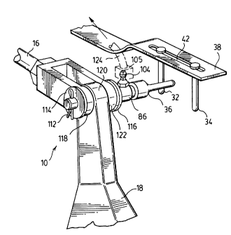
As shown in Figures 9, 10 and 11 clevis pin 64 of the present
invention has been designed to prevent, or reduce the tendency of,
clevis pin 64 seizing in push rod 16 and/or brake arm 18. Clevis pin 64
is designed to operatively and pivotally connect yokes 118 and 122 of
pushrod 16 to yoke 120 of brake arm 18 such that the contact surfaces
(which define pivoting surfaces) are provided with lubricant to
facilitate smooth independent movement of these brake system
components.
Clevis pin 64 preferably comprises a substantially cylindrical
elongate body so as to define a pivot surface for yokes 118 and 122 of
pushrod 16 and yoke 120 of brake arm 18. Clevis pin 64 has an outer
CA 0224~28~ 1998-08-10
- 16-
surface 80, a first end 84 and a second end 82.
If clevis pin 64 is to be used in conjunction with the brake
adjustment indicator discussed herein, the clevis pin 64 preferably has
an enlarged portion 86, preferably of cylindrical shape, located in the
region of first end 84 for receiving bore 94. In this embodiment, clevis
pin 64 may also have a knob 88, preferably of substantially cylindrical
shape, located at first end 84 and a recessed groove 90, preferably of a
circumferential nature, located between enlarged portion 86 and knob
88. Knob 88 and recessed groove 90 define a mounting base on which
flexible indicator 36 may be securely attached. Alternately, indicator 36
may be integrally formed with clevis pin 64 in which case, knob 88 and
groove are not required.
Clevis pin 64 is preferably provided with a lubrication
channel network comprising a plurality of passageways to provide a
lubricant to at least some of the pivoting surfaces and, preferably, to all
of the pivoting surfaces. As shown in Figure 9, three passageways,
namely first lubricant channel 92, threaded cross-bore 94, and second
lubricant channel 96 are provided. First lubricant channel 92 extends
generally axially within clevis pin 64. First lubricant channel 92 may be
prepared by drilling in a longitudinal fashion through first end 84 to an
intermediate point between first end 84 and second end 82. Threaded
cross-bore 94 extends inwardly from the outer surface of enlarged
portion 86 to the axis of clevis pin 64, such that threaded cross-bore 94 is
positioned over, and communicates with, first lubricant channel 92.
Second lubricant channel 96 extends transversely through clevis pin 64
between lubricant holes 98 and 100. Second lubricant channel 96
intersects first lubricant channel 92 such that lubricant holes 98 and 100
on outer surface 80 are in flow communication with first lubricant
channel 92.
Threaded cross-bore 94 is dimensioned to securely receive a
grease fitting 102, such as a threaded grease fitting (eg. a commercially
available Welsh plug). In turn, grease fitting 102 is dimensioned to
CA 0224~28~ 1998-08-10
- 17-
receive a commercially available grease nipple 104. Accordingly,
enlarged portion 86 is preferably dimensioned so that threaded cross-
bore 94 provides sufficient thread depth to properly secure grease fitting
102 therein.
Threaded cross-bore 94 permits ready communication and
transmittal of lubricant from grease nipple 104 to first lubricant
channel 92, which in turn provides lubricant through second lubricant
channel 96 to surface 80 of clevis pin 64 through lubricant holes 98 and
100. Accordingly, first lubricant channel 92, threaded cross-bore 94 and
10 second lubricant channel 96 provide a continuous path for lubricant to
flow from grease nipple 104 to outer surface 80 of clevis pin 64 adjacent
lubricant holes 98 and 100.
Lubricant holes 98 and 100 are preferably located on the
section of outer surface 80 of clevis pin 64 which are oppo~d to yokes
15 118 and 122 of pushrod 16 and/or yoke 120 of brake arm 18. It should be
apparent that more than one second lubrication channel 96 may be
provided within clevis pin 64 so as to provide additional deposits of
grease at altemate locations along the length of clevis pin 64. If only
one second lubrication channel 96 is provided, it is preferably
20 positioned opposed to yoke 120 of brake arm 18.
In the embodiment of Figure 9, a threaded axial opening
106 is provided along the inner surface of first lubrication channel 92,
projecting inwardly from first end 84. Axial opening 106 is
dimensioned to receive a threaded plug 108 which is preferably used to
25 prevent lubricant from leaking out of the opening 106 during use of
clevis pin 64. If flexible indicator 36 is not secured to clevis pin 64, then
a grease fitting and grease nipple may be secured within axial opening
106 as an alternative to the use of threaded bore 94.
Preferably a retention channel 110 having ends 111 extends
30 through clevis pin 64, transversely to the axis of clevis pin 64 with both
ends 111 communicating with outer surface 80 in the region of second
end 82. Retention channel 110 is adaptable to receive a retention
CA 0224~28~ 1998-08-10
..
- 18-
member such as a cotter pin. Accordingly, clevis pin 64 may be
removably mounted within the yokes of push rod 16 and brake arm 18.
Figure 11 shows clevis pin 64 installed and in use with
vehicle brake adjustment indicator system 10. When it is desired to
grease clevis pin 64, a grease gun or a greasing tube 109 of an automatic
greasing system of a truck may be affixed to grease nipple 104 which in
turn provides lubricant automatically to outer surface 80 of clevis pin
64 adjacent lubricant holes 98 and 100. As the yokes of pushrod 16 and
the yoke of brake arm 18 rotate around clevis pin 64 during the
operation of brake system, grease is distributed along the section of
outer surface 80 which is in direct moveable contact with the yokes of
pushrod 16 and brake arm 18.
Cotter pin 112 at second end 82 of clevis pin 64 is shown
providing retention for clevis pin 64 within the yokes of push rod 16
and brake arm 18.
Spacer rings 114 and 116 may be provided as shown, each
having an inner diameter which conforms to the diameter of outer
surface 80 of clevis pin 64. Accordingly, spacer ring 114 may be
positioned between cotter pin 112 and first yoke 118 of pushrod 16; yoke
120 of brake arm 18 may be operatively connected to clevis pin 64
between first and second yokes 118 and 122 of pushrod 16; and, spacer
ring 116 may be positioned between second yoke 122 and enlarged
portion 86.
As shown, knob 88 is provided at first end 84 of clevis pin
64. Knob 88 with recessed grove 90 together provide a mounting base
on which flexible indicator 36 may be securely attached. Since flexible
indicator 36 consists of a hollow elastomeric member, when opening 66
is placed over knob 88, outer edge of opening 66 may be secured within
recessed groove 90 due to the elasticity of flexible indicator 36.
Grease nipple 104 may be attached to an automatic greasing
system for a truck in order to ensure a regular and continuous supply
of lubricant to clevis pin 64 through a greasing tube 124. Automatic
~ CA 0224528~ 1998-08-10
- 19 -
greasing syslems are typically run by electronic control units which
control the sequence interval and the pressurization time of the
lubricant delivery to parts within a truck. Fixed doses of lubricant can
be supplied by the system through greasing tube 124 to meet the
5 particular lubricant need of clevis pin 64. In this way, regular
lubrication of clevis pin 64 will reduce the seizing of clevis pin 64
within the yokes of pushrod 16 or brake arm 18.
It will be appreciated by those skilled in the art that other
modifications may be made to the brake adjustment indicator and are
10 within the scope of this invention.