Note: Descriptions are shown in the official language in which they were submitted.
CA 0224~299 1998-08-19
-
Title: Grid-like building panel framework and members for
making such panel framework.
Backqround of the invention.
l.Field of the Invention
The present invention relates to building panels,
particularly for the construction of houses. The invention
is particularly concerned with a framework or skeleton panel
which is formed as a grid of intersecting members, usually
of wood-based material. The term "panel" will be used herein
to include such a panel framework, and does not imply that
this is a finished panel with insulation and/or facing
sheets.
2.Prior Art
It is known to construct houses, and other buildings,
from panels which are factory made, and which usually
contain insulation. Examples of patents showing such panels
are as follows:
U.S.Pat.No.4,671,032, whichissued Jun.9,1987 to
Reynolds;
U.S.Pat.No.4,765,105, whichissued Aug.23,1988 to
Tissington et al.;
U.S.Pat.No.4,894,974, whichissued Jan.23,1990 to
Mayhew et al.
U.S.Pat.No.5,157,892, issued Jun.9,1987 to Ryther; and
U.S.Pat.No.5,167,700, issued Apr.8,1997 to Wright et
al.
Applicant has had considerable experience both with the
panels of the last-mentioned '700 patent, of which he is co-
inventor, and with those of the Tisssington et al. patent.
Both these patents are concerned with factory made panels
having a framework made of wood members, and insulated with
CA 0224~299 1998-08-19
rigid foam insulation injected between the wood members in
the factory. In the last-mentioned patent, dimensional
lumber is used to provide strength, while in the Tissington
et al patent it is preferred to use board such as oriented
strand board (OSB). OSB is cheaper than standard dimensional
lumber and is more resistant to warping. These panels have
been used to construct over one thousand buildings of many
different types, with great success.
Panels of the type shown in the Tisssington et al.
patent and in the '700 patent have great potential in export
markets, since buildings can be erected with these panels
using largely unskilled labor. However, it has become
apparent that a serious drawback of these and similar
panels, i.e panels fully assembled and insulated in the
factory, is that the bulkiness of the insulation leads to
high shipping costs which are disadvantageous for export
markets. The shipping costs could be much reduced if it were
possible to ship a kit of structural members which could
easily be assembled into a panel on site, without the need
to ship the insulation.
The present invention accordingly is concerned with a
panel in the form of a framework which can be shipped in
disassembled form, without any insulation. The basic
structural members of the panel occupy about one-fifth of
the volume occupied by a fully assembled and insulated,
factory produced panel. The structural members of the panel
can easily be assembled on site by unskilled workers to form
a rigid panel framework. Insulation, and facing sheets for
example of plywood, OSB, and many other materials, can be
added in accordance with local requirements and
availability.
The present invention makes use of novel structural
members which can easily be put together to form a grid.
Panels formed as grids of crossing, interlocking members,
CA 0224~299 1998-08-19
are not new per se, and the Mayhew and Ryther patents, as
well as the '700 patent aforesaid, show such panels.
However, the prior art panels have various drawbacks.
One drawback of many of the prior art designs is that
the grid forming members, as for example in Mayhew et al.
and Ryther, are too thin for their edges to reliably receive
nails for the facing sheets.
Another drawback has been the need to use structural
members additional to those of the basic panel itself.
Firstly, such panels have generally needed some kind of
rails or studs or side pieces to improve the appearance of
any exposed edges of the panels, which otherwise show the
ends of the lateral members. Such rails or studs are shown
for example at 240 in Fig.2 of Mayhew, and as 28 in Fig.1 of
Ryther. Secondly, the grid forming members in many cases
have not been stiff enough to be used exclusively to form
the panel; in Mayhew et al. the members 240 are in the
nature of studs which add strength and stiffness.
Accordingly, these prior constructions all require the use
of members other than the basic grid forming members to
complete the panel framework.
One special feature of this invention is that a panel
framework can be entirely formed from a plurality of
structural members of novel design, which can be all
identical or can be of only two different designs. These
basic members are used not only for the horizontal and
vertical members of the panel grid, but also form its four
edges, i.e. the side edges and end (e.g. top and bottom)
edges of the panel, where they provide smooth relatively
uninterrupted edge surfaces, while producing a panel of good
strength and rigidity. The panel also has adequate nail
receiving surfaces on both sides, even when formed of
relatively thin material such as 3/4 inch thick OSB.
Insulation and facing sheets can be added after assembly.
CA 0224~299 1998-08-19
Furthermore, the novel structural members can also be
used to produce beams and joists needed for building a
house, and also floor panels which need higher strength than
the basic wall panels. In fact it is possible to construct
houses almost entirely from panels, joists and other parts
produced from these one or two types of structural member,
along with facing sheets, and insulation if required, which
can be obtained locally. This avoids the need to organise
shipments of the many different structural members usually
I0 needed to make a house, and avoids problems which frequently
occur if there is a shortage or breakage of one or two
structural members of a specialized design.
Summary of the Invention
In accordance with one aspect of the invention, a
I5 building panel framework, having opposite first and second
sides, is formed of a plurality of primary and secondary
structural members, each of which has a web and a flange
providing the member with a T-shaped cross-sectional shape,
and each of which has a series of transverse notches spaced
along its web.
The panel includes a first series of the primary
members which are spaced apart and parallel to each other
with their flanges defining the first side of the panel, and
a second series of the secondary members, usually cross
members, spaced apart and parallel to each other and
extending transversely to the members of the first series,
and with their flanges defining the second side of the
panel. The primary members have the transverse notches of
their webs engaging areas of the opposing webs of the
secondary members adjacent their transverse notches, so that
the primary and secondary members form a grid with their
flanges defining the opposite sides of the panel.
The use of T-shaped structural members means that each
CA 0224~299 1998-08-19
member has a flange on one side or the other of the panel
and these flanges can readily receive nails, or other fixing
means for facing sheets. Also, T shaped structural members
are of course more rigid than the flat members used in the
panels of Mayhew and Ryther, referred to above.
Another advantage of the use of T-shaped members is
that, where the members have similar dimensions, they allow
a double interlock to be made between the crossing members,
which prevents unwanted twisting of the members. For this
purpose notches in the webs of the members each have an
inner, relatively narrow, portion for receiving part of the
web of the crossing member, and an outer, relatively wide
portion for receiving part of the flange of the crossing
member, and the flanges of the members have opposed side
notches which engage with parts of the web of the crossing
member at the ends of the notch outer portions. Thus, each
member engages another member not only at the web but also
at the flange.
Yet another advantage of the use of T-shaped members is
that these same members can also form edge members for the
panel, and which present smooth, relatively uninterrupted
edge surfaces. These the edge members are the same as other
members making up the panel but are, in effect, rotated
about their axes through 90~ so as to have their flanges
facing outwardly from the lateral edges of the panel and
lying in planes perpendicular to the opposed first and
second panel sides. These members thus have their webs
projecting inwardly towards the center of the panel and
disposed parallel to and between the opposed sides of the
panel, the transverse notches of the inwardly facing webs
being engaged with the ends of the webs of the members
forming the grid. For this purpose the ends of the webs can
be provided with longitudinal notches.
Preferably, each structural member has its web off-set
-
CA 0224~299 1998-08-19
from the center of its flange, such that one side of the web
is at the center of the flange. This allows the edge members
to include a first pair of edge members at opposite side
edges of the panel having their webs nearer to the first
side of the panel than the second side, and a second pair of
edge members at opposite end edges, e.g. top and bottom
edges, of the panel, the webs of the second pair being
nearer to the second side of the panel than the first side,
the webs of the second pair overlapping the webs of the
first pair, and with the edges of the flanges of all the
edge members being coplanar.
In a particular case, the panel of the invention is
formed of a plurality of identical structural members, the
primary and secondary structural members only differing in
their orientation. This is obviously advantageous from a
production point of view, and leads to minimum difficulty in
assembly, and minimum supply problems with missing or broken
members.
Having all the structural members identical is suitable
where all or most of these are used to produce wall panels;
it will be understood that there may be local reasons for
using other members, perhaps available locally, for roofs or
floors. However, if the structural members of this invention
are also needed for roofs and floors, the use of identical
members has the drawback that all have a relatively deep
notch, about one half the depth of the web, and are
therefore somewhat weak in bending. One solution to this
problem is to combine the structural members with other such
members, or with other local materials, to make suitably
strong beams or roof or floor panels. However, a more
satisfactory solution is to provide two distinct primary and
secondary structural members, with the primary members
(which will be the vertical members or props when used in a
wall panel and will be the longitudinal members in a floor
panel) having a large web with shallow notches and good
CA 0224~299 1998-08-19
strength, and the secondary members (the cross members in a
wall or floor panel) having a narrower web and lesser
strength. The notches in the primary member are preferably
less than one-third the total height of the member, and in
practice may be less than one-quarter the total height of
the member. Either, or preferably both, members are used for
the panel edges.
In order for the members which constitute the edge
members to fit together, the ends of the edge member flanges
are preferably rabbeted, i.e. formed with recesses so as to
have end projections which can fit into the recess of an
adjoining member. Also, the ends of the members may each
have a peg which, when used as an edge member, engages in an
aperture in the mating edge member.
Brief DeQcription of the Drawings.
Preferred embodiments of the invention will now be
described by way of example with reference to the
accompanying drawings, in which;
Fig.1 shows a perspective view of one form of the novel
structural member, which can be used with identical members
to form a panel;
Fig.2 is a perspective view of a joint between two of
the structural members of Fig.1,
Fig.3 shows a perspective view of a partly constructed
panel formed of these members;
Fig.4 is an end view of a beam formed of two structural
members of Fig.1;
Fig.5 is a perspective partial view of primary and
secondary types of members of different design which can be
used to produce panels in accordance with the invention;
Fig.6 is a side view of portions of the members shown
in Fig.5 before assembly;
Fig.7 is a side view of a joint between the members of
Figs.5 and 6, and incorporating a splice member;
CA 0224~299 1998-08-19
Fig.8 is a further view of the same joint, on lines 8-8
of Fig.7;
Fig.9 shows part of a panel framework constructed of
the members shown in Fig.5, with parts of an adjacent panel;
5Fig.10 is a fragmentary detail view of Fig.9 of the
joint between two edge members;
Fig.11 is a view of the primary member of Fig.5 which
has been modified to receive an additional flange part;
Fig.12 shows the side view of parts of panel frameworks
of Fig.5, when incorporated into a floor panel;
Fig.13 is a view similar to Fig.12 of an alternative
joint construction between two floor panels,
Fig.14 shows a top view of portions of an alternative
floor panel construction, and
15Figs.15 to 19 show end views and end portions of beams
and posts formed using the structural members of this
invention.
Detailed DescriPtion.
The structural members 10, 10' and 10'' shown in Figs.1
to 4, which are all identical, each comprises a flange 12
and a web 14 both formed of 3/4 inch (1.9 cm) thick oriented
strand board (OSB). The flange 12 has a width W (indicated
in Fig.4) of about 4 inches (10.16 cm), and has a dado
groove which receives the edge of the web; the web is
dimensioned to give the member an overall height H of about
5 1/2 inches (14 cm). The web is off-set so that one of its
sides is at the center of the flange, and so that the web of
one member can be overlapped with and secured to the web of
another member, as shown in Fig.4, while the flanges of the
two members have edges lying in common planes.
The web 14 has notches 16 evenly spaced along its
length; with the member having an overall length of 8 feet
(2.43 metres), the notches would be spaced on 2 foot (61 cm)
centers. The notches each have an inner, relatively narrow
CA 0224~299 1998-08-19
portion 16a suitable for receiving the 3/4 inch (1.9 cm)
wide web 14 of an identical crossing member, indicated at
10' in Fig.2, and each notch has an outer, relatively wide
and shallow recess 16b for receiving part of the flange of
the crossing member. At the same longitudinal locations
along the structural members the flanges 12 are provided
with small symmetrical notches 18 on their opposite sides,
which are 3/4 inches (1.9 cm) wide and 5/8 inches (1.6 cm)
deep. The arrangement is such that, as shown in Fig.2, two
identical structural members can be fitted together, when
extending perpendicularly to each other and with their webs
opposed and flanges facing outwardly, a notch portion 16a of
the first member web engaging an area of the opposed web of
the crossing member adjacent one of its notches, and the
recesses 16b of the first member web accommodating parts of
the flange 12 of the second member between its notches 18.
With this arrangement, the outer face of the flange of the
first member is coplanar with the outer edge of the web of
the second member, and vice versa. Also, the arrangement
provides a double interlock between the two members, at the
web and flange of each members, preventing twisting such as
can occur with the usual single interlock shown in the prior
art grid arrangements.
It will be seen with reference to Fig.3 that a
framework panel or grid of the members 10, 10' etc. can be
built up in this way, having a first series of primary
members 10 parallel to each other with their flanges 12
coplanar and effectively forming one side of the panel, and
a second series of identical, secondary members 10'
extending parallel to each other and perpendicular to the
members of the first series, and with their flanges forming
the second, opposite side of the panel, and with the outer
edges of the webs of first type of member being co-planar
with the flanges of the other type of members.
_ With the two series of members engaged as described,
CA 0224~299 1998-08-19
the ends of the members protrude from the sides of the
panel. A unique feature of the grid or framework of this
invention is that additional identical members 10'' can be
used as edge members to provide smooth, relatively
uninterrupted edges to the panel. For this purpose the ends
of the webs are provided with longitudinal notches or slots
20 of 3/4 inch (1.9 cm) width and about 3 1/2 inches (8.9
cm) deep, and the ends of the flange are formed with rabbets
or recesses 22 leaving projecting end parts 22a. The
projecting end parts 22a are associated with small
projections 23 near the flange edges of the webs, and
similar small projections 24 are formed near the outer edges
of the webs. The slots 20 receive the areas of the webs of
edge members 10'' under their notches 16a; these members
10'' are rotated 90~ about their axes relative to the
orientations of the other members so that their webs project
inwardly, being parallel to the panel faces, and their
flanges face outwardly of the panel edges and are orientated
perpendicularly to the sides of the panel. The off-set
nature of the webs allows one pair of opposite edge members
to have their webs nearer the first side than the second
side, and the other edge members to have their webs nearer
to the second side than the first side, while at the corners
the two adjacent ends of the edge members have their webs
overlapping and in contact with each other while their
flanges have coplanar edges. Also at the corners, the
projecting end portions 22a of one edge member fit into the
recess or rabbet of an adjoining member. The projecting end
portions 22a of the members forming the grid extend over the
flanges of the edge members, and can be fixed thereto, while
the small projections 23 and 24 engage in the side notches
18 of the edge member flanges. The ends of the webs 14 also
have recesses 26 formed in their outer corners, these being
1 3/8 inch (3.5 cm) in length and 3/4 inch (1.9 cm) in
depth. When these members are used vertically in a wall
panel, these recesses 26 can accommodate the notched
portions of the flange of a further reinforcing member laid
CA 0224~299 1998-08-19
along the top of the panel.
The members may be held together with staples or glue,
preferably both. Nails are preferably avoided in the
construction of the framework, since there is often a need
to cut into the members of a completed panel, for example to
provide window openings. The assembled members provide a
panel with good rigidity, even before facing sheets and
nails are applied.
The panel framework can be finished by applying
insulation, if needed, electrical wiring, and facing sheets
or siding may be nailed onto the flanges on the opposed
sides. The insulation may be batts fitted in between the
members. The facing sheets may be material locally such as
stucco grid or plywood sheets. Unlike in prior art patents
showing grid construction, the facing sheets can be attached
with nails, since these can be driven into the relatively
wide flanges 12, and one does not have to rely on driving
nails into the narrow edges of the OSB material.
The panel produced as described has a length and height
of 8 feet (2.43 metres). The formation of longer panels by
joining similar members is discussed below.
Fig.4 shows an end view of a joist, formed of two
members 10 having their webs 14 held together side-by side;
this forms an I beam. It will be seen that the off-set
nature of the webs is such that with the webs connected
together, the edges of the flanges are co-planar. Stronger
and more complex beams are described below.
The use of identical members is suitable for wall
panels, and is obviously advantageous from a production
point of view, and simplifies construction. However, in
order for the edges of the webs of these members to be co-
planar with the flanges of the crossing members, the webs
CA 0224~299 1998-08-19
need to be notched to one-half the member height (H), and
this makes the panel undesirably weak for use as floor or
roof panels. When this is desired, there are two ways of
improving the bending strength of the members and panels
formed therefrom, i.e.:
a) using identical members which have notches of less
than one half their depth, so that in the assembled panel
the flanges on each side of the panel stand out beyond the
edges of the webs on that side; or
b) using two types of members, both similar to the
single type previously described in each having a flange and
a web, with spaced notches in the web, but in which a series
of primary members each have a large web and small notches,
capable of providing good bending strength lengthwise of the
panel, while secondary members each have a small web, also
with small notches, and which provides adequate strength for
the lateral direction of the panel.
The latter form of the members, which is preferred,
will now be described in relation to Figs.5 to 10 of the
drawings.
As shown in Fig.5 a primary structural member 30 has a
flange 32 of 4 inches (10.16 cm) width, with a dado groove
which receives a web 34 giving the member a total height of
5 1/2 inches (14 cm). As before, the web has one of its
sides coincident with the center of the flange so that the
webs of two members can lie side-by-side with the edges of
their flanges aligned. The web 34 has notches 36, one of
which is seen in Fig.6, which are similar to notches 16,
except that the narrow portions 36a of the notches are
relatively shallow, being only 1 3/8 inches (3.5 cm) in
depth, i.e. less than one-quarter the total height of the
member. The wider, shallower notch portions 36b are 2 3/4
inches (6.98 cm) wide and 3/4 inches (1.9 cm) deep. The web
34 has end slots 40 similar to those of member 10, and which
are 3 1/2 inches (8.9 cm) deep. Also, the end of each web
CA 0224~299 1998-08-19
34, between the notch 40 and the web outer edge, has a
longitudinally projecting rectangular peg 35, and a recess
46 which serves the same purpose as recess 26 in the first
embodiment. Also, spaced below the slot 40 is a projection
41 which is flush with a projecting end portion 42a of the
flange 32; the other end portion 42 of the flange is
recessed to form a rabbet. As before, the flange 32 has side
notches 38, these being 5/8 inch (1.6 cm) in depth and 3/4
inch (1.9 cm) in width.
The secondary member 50 shown in Fig.5 is again similar
to member 10, except in the form of its web and end
formations. It has a flange 52 which is similar to that of
the member 10, having the same side notches shown at 58,
which are the same dimensions as notches 38. Its web 54 is
much shallower than web 34, so that the total height of the
member 50 is only 2 inches (5.08 cm). The notches 56 in the
web 54 include a primary notch 56a of 3/4 inch (1.9 cm)
depth and the same width, adjoining an auxiliary notch 56b
of 1/2 inch (1.27 cm) depth and 3/4 inch (1.9 cm) width. The
auxiliary notch has a chamfered side portion shown at 56c.
Another difference over the members 10 is that the
outer surface of the flange 52 has chamfered outer surfaces
52a near its edges, as seen in Figs.6, 7 and 8.
As before, the ends of the flanges 52 of the secondary
member have rabbets, shown at 60, but here the rabbet also
has a notch 62, close to the side of the web, and further
has a circular hole 63 longitudinally aligned with this
notch. The notch 62 and hole 63 are positioned and sized to
receive, respectively, the projection 41 and the peg 35 at
the end of the primary member when the two members are used
as edge members and meet at a corner of the panel as shown
in Fig.10.
Figs.7 and 8 indicate how the joints between the
CA 0224~299 1998-08-19
primary and secondary members are formed, with the notched
areas of the primary web 34 engaging the notched areas of
the secondary web 54, and the side notches 58 of the flange
52 engaging the web 34 at the sides of the outer portions
36b of the notches. This construction can be used to build
up a panel as shown in Fig.9.
Figs.7 and 8 also show a further use of the secondary
member 50; a short length, for example a 2 foot (61 cm)
length, of such member 50' can be used as a splice for
connecting two primary members end-to-end. As shown, the
member 50' is fitted with the outer surface of its flange 52
lying against the webs 34 of the two connecting primary
members, this being possible since the width of the flange
52 (about 4 inches or 10.16 cm) is the same or no wider than
the space provided by the primary member web between its
flange 32 and the flange 52 of the grid-forming secondary
member 50. A notch 58 of the flange 52 of member 50' engages
the web 54 of the member 50 at its auxiliary notch 56b. The
member 50' is inserted by a tilting action, as indicated in
broken lines, this being made possible by the chamfered
outer surface of the flange 52 of the member 50' and the
chamfered side 56c of the auxiliary notch of the grid-
forming member 50. The member is secured to the web 34 to
provide a splice connecting the primary members end-to-end.
Preferably the member 50' is a snug fit between the opposed
flanges 32 and 52.
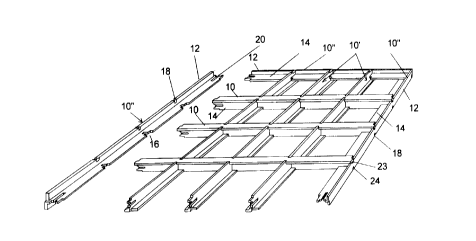
Fig.9 shows how the primary and secondary members are
assembled into a floor panel, and indicate members 50' which
can be used to connect the primary members of this panel to
similar members, such as member 30', of another panel. The
stronger primary members 30 are used longitudinally, and the
secondary members 50 are used as cross members of the grid.
At opposite sides of the each panel further secondary type
members 50'', rotated 90~ about their axes, are used as edge
members. The grid forming secondary members have the edges
CA 0224~299 1998-08-19
of their webs secured to sides of the webs of the edge
members 50'', and do not require slots as do the primary
members.
At the near end of the panel (as shown) the primary
members 30 of the grid mate with a primary member 30'' used
as an edge member, having its web 34 engaging the slots 40
in the members 30, and with the pegs 35 and projections 41
at the ends of members 30 engaging the side notches 38 of
the member 30''. Also, as shown in Fig.10, the pegs 35 and
projections 41 at the ends of the member 30'' fit into the
notches 62 and hole 63 at the ends of the side edge members
50'', with the web 34 of member 30'' lying beside the webs
54 of the side edge members.
It is also possible to use four of the primary members
30 as edge members for a panel, but in this case it is
necessary to cut off pegs 35 which cannot be accommodated by
mating flanges.
The type of panel shown in Fig.9 can also be a wall
panel, in which case the primary members 30 will be used as
vertical members, comparable to building studs. Apart from
providing a panel which is better able to resist vertical
forces than that of Fig.4, the Fig.9 panel also has the
advantage that is easier to insulate. When an outer facing
sheet has been applied to the flanges 32, insulation can be
applied to the interior of the panel by being slid into the
space behind the cross members 50; a clear space 3 1/2 (8.9
cm) deep being provided behind these members.
Fig.11 shows a variation 130 of the primary member 30
which is suitable where the wall surface adjacent the edges
of the webs 134 is to be finished with gypsum type wallboard
or so-called "dry-wall". The outer edge of the web 134 is
cut back by 1/2 inch (12 mm) from the usual outer edge
position, which is shown in broken lines. This allows
CA 0224~299 1998-08-19
additional flange parts 132, which are narrow strips about
2 or 3 D (5 or 7.5 cm) width having a central dado groove
1/2 inch (6 mm) deep, to be applied to the outer edges of
the web 134, between the crossing secondary members 50, thus
giving a flat support surface for the wallboard.
Fig.12 shows how the members shown in Fig.5 can be used
to build up a strong, double thickness, floor panel. As
shown, one upper panel P, similar to that of Fig.9, is
placed on top of the abutting end portions of two lower
panels P' and P''. The members 30 of the top panel overlie
abutting end portions of members 30' and 30'' of the lower
panels, and members 30' and 30'' are joined end-to-end by a
portion of a secondary member 50' acting as a splice member,
as in Figs.7, 8 and 9.
Thus, the joints in this floor panel only rely not only
on splice members 50', but on an upper or lower panel part
which is continuous above or below the joint. Using upper
and lower staggered joints in this way allows a long floor
of good strength to be produced.
It will be noted from Fig.12 that the centerline
spacing of the secondary members 50 at adjacent ends of the
lower panels P' and P'' is the same, namely 2 feet (61 cm),
as the spacing of the members of the upper panel P. The end
portions of the grid forming members 30 and 50 are
dimensioned so that this spacing is maintained whenever a
panel is joined to another panel.
While Fig.12 shows the primary members of the upper and
lower panels aligned, this is not essential, and the primary
members of the upper panel may be aligned with secondary
members of the lower panel. This alignment gives some
advantages in terms of the space for ducting which is
provided in the combined panels, and in terms of the cross-
wise stiffness.
CA 0224~299 1998-08-19
Fig.13 shows a floor construction having an upper panel
P and a lower panel P', in which the primary members of the
upper and lower panels are aligned, as in Fig.12, but in
which secondary members 50 are arranged to be shared between
the two panels. In building up the lower panel P', the
members 50 are rotated 90~ about their axes from the usual
orientation, and have their side notches 58 engaged with the
notch portions 36a of the members 30', while the notched
area of the web 54 of these members engages the sides of the
webs 34 at the ends of the notch portions 36b. The upper
primary member 30 also has its web engaged with the side
notches 58 of the members 50. This has the advantages of
locking together the upper and lower primary members, and of
providing additional bending strength in the cross-wise
direction, while using only half the number of secondary
members as compared to the Fig.12 type construction.
Fig.14 shows another way that a long panel may be
produced, particularly if this is to have only a single
thickness, rather than the double thickness of Figs.12 and
13. As in Fig.9, members 50' are used to produce joints
between the abutting ends of members 30, but here the joints
J are staggered across the panel so that each panel width
has only one joint at each longitudinal location. As before,
the dimensioning of the end portions of the members means
that a 2 foot centerline spacing is maintained across the
panel whether or not there is a joint.
Figs.15 to 19 show some of numerous beams and posts
which can be produced using the members of this invention,
and which have various uses in buildings.
Fig.15 is somewhat similar to Fig.4, but has two of the
members 30, rather than members 10, and uses these in
association with flat strips 60 of OSB to give greater
distance between the flanges 32, and therefore better
bending strength.
CA 0224~299 1998-08-19
Fig.16 shows a post formed of two complete primary
members 3Oa and 3Ob, combined with the web and part of the
flange of a third primary member 30c. The broken lines
indicate the flange part of the member 30c which has been
cut off. Fig.17 shows a square post formed of one primary
member 30, three secondary members 50a, 50b, and 50c,
combined with two flat strips 62, 63, of OSB.
Figs.18 and 19 show beams which can be made using
primary or secondary members 30 or 50, along with other
parts including steel bracket parts 70. The latter may be
similar to material available commercially for shelf
brackets, and having a series of straight sections connected
by right angle corners to produce a zig-zag configuration.
As shown in Fig.18, upper and lower secondary members 50
have their webs coplanar and projecting towards each other,
and joined by short lengths of secondary members 50'. On one
side of the webs there extends a steel zig-zag member 70
which has its corners fixed, as by screws 71, to the inner
faces of the flanges 52. An even stronger beam is shown in
Fig.18, where two primary members 30 have abutting webs 34
joined by short lengths of secondary member 50' extending
between their flanges 32, these flanges again being joined
by attachment to the corners of the member 70.