Note: Descriptions are shown in the official language in which they were submitted.
CA 0224~470 1998-08-2
SPECIFICATION
HYDROGEN BURNING TURBINE PLANT
BACKGROUND OF THE INVENTION:
Field of the Invention:
The present invention relates to a hydrogen burning
turbine plant for burning hydrogen and oxygen to generatesteam
for thereby driving a turbine, and specifically to such of
turbine plant in which a turbine operation at starting time is
facilitated and a steam utilizing efficiency is enhanced.
Description of the Prior Art:
Aconceptofahydrogenburningturbineplant inwhich
hydrogen and oxygen are burned at a combustion apparatus to
generate steam of about 3,000~C for thereby driving a turbine
is presently being studied and systems thereof having various
features are known now. But in the practical usethereof, there
are various problems so that it is the present situation that
an ensured technology has not been obtained yet. Examples of
such a hydrogen burning turbine plant will be shown in Figs.
5 and 6 with outlined description as herebelow.
In a system of Fig. 5, which is disclosed in the
Japanese laid-open patent No. Hei 6(1994)-299805, a cycle of
steam is constructed such that a low temperature steam from a
compressor 52 becomes a high temperature steam at a hydrogen
CA 0224~470 1998-08-2~
oxygen combustor 50 and enters a turbine 53 for driving it so
that power is generated at a generator 54, and then the steam
which has become a low temperature steam flows in a heat
exchanger 55 and returns to the compressor 52. On the other
hand, the low temperature steam which has come out of the
turbine 53 drives a condensing turbine 63 for thereby driving
a generator 64 for power generation and is condensed to water
at a condenser 65. Also, another cycle of steam is constructed
such that water fed by a pump 62 is heated at the heat exchanger
55 to become steam and enters an expansion turbine 56 for
thereby driving a generator 57 for power generation, and then
the steam which has become a low temperature steam is heated
to a high temperature at a hydrogen oxygen combustor 58, enters
a condensing turbine 59 for thereby driving a generator 60 for
power generation and is condensed to water at a condenser 61,
and then flows to the heat exchanger 55 again via the pump 62.
In the present system, exhaust heat is recovered downstream of
the turbines and two units of the hydrogen oxygen combustors
are provided, to thereby aim at a higher efficiency.
Fig. 6 shows another example of system using a
hydrogen oxygen combustor. In the figure, a cycle of steam is
constructed such that steam fed through a low pressure
compressor 100, an intercooler 101 and a high pressure
compressor 102 enters a hydrogen oxygen combustor 104 through
a first heat exchanger 103, is heated there to a high
CA 0224~470 1998-08-2~
temperature to drive a first turbine 105 for thereby driving
a generator114 forpower generationand then flows inthe first
heat exchanger 103 and a second heat exchanger 106 for giving
exhaust heat, and after flowing through a third heat exchanger
107, the steam on one hand drives a second turbine 109 for
thereby driving a generator 115 for power generation and the
steam on the other hand flows through a fourth heat exchanger
108 to enter the low pressure compressor 100 again. The steam
which has become a low temperature steam after flowing in the
second turbine 109 is condensed to water at a condenser 111,
is heated at a first feedwater heater 117 and a second feedwater
heater 118, flows in the fourth and third heat exchangers 108,
107 via a pump 112 to be heated by the exhaust heat and further
to be heated to a high temperature at the second heat exchanger
106 and drives a third turbine 110 for thereby driving a
generator 116 for power generation, and then the steam which
has becomea lowtemperaturesteam is partiallyused forcooling
of the first turbine 105 and remaining steam is returned to an
outlet side of the high pressure compressor 102 to flow in the
first heat exchanger 103. Numeral 119 designates the cooling
steam forthe firstturbine105. Inthepresentsystem, inorder
to attain a high efficiency of the compressors without making
the pressure ratio higher, the system is so constructed that
there are provided the heat exchangers for making heat
exchanges between the upstream side of the hydrogen oxygen
CA 0224~470 1998-08-2~
combustor and the downstream side of the first turbine and the
exhaust heat is made use of efficiently.
As mentioned in the prior art examples of Figs. 5 and
6, with respect to the system having the combustion apparatus
for burning hydrogen and oxygen to generate a high temperature
steam for thereby driving a turbine, there are considered and
studied systems having various features for making effective
- use of the high temperature heat generated there for obtaining
a high efficiency. In order to make practical use thereof,
however, because the steam generated by burning hydrogen and
oxygen is of a high temperature of about 3,000~C, it becomes
necessary to obtain a means of operation by which said high
temperature steam at starting time is diluted and reduced to
a temperature which is able to be introduced into the turbine.
But, however various systems are considered at present, it is
an actual situation that there is no established system yet for
appropriate start and rise of such systems.
Also, unless the control system is appropriate for
starting time until the steam condition of pressure and
temperature is established at each portion of the cycle, wet
steam comes in thecompressor orturbine and there arises a risk
of breakage thereof. It is necessary, therefore, to obtain an
established system for watching conditions at each portion of
the plant and controlling flows of steam there appropriately.
In the present state hydrogen burning turbine plant, although
CA 0224~470 1998-08-2~
systems having various features are disclosed, there is
established yet no sufficient control system for effecting an
operation as an actual plant.
Further, in a prior art hydrogen burning turbine
plant shown in Fig. 7, while a portion of exhaust gas (steam)
coming out of a third turbine 110 is sued as a cooling steam
for turbine blades etc. of a first turbine 105, in order to
obtain a higher efficiency of this turbine plant, it becomes
necessary to reduce the cooling steam of the first turbine 105
as much as possible or to employ such a cooling system as having
less lowering rate of a gross thermal efficiency.
SUMMARY OF THE INVENTION:
It is therefore an object of the present invention
to provide a hydrogen burning turbine plant for burning
hydrogen and oxygen to generate a high temperature steam for
thereby driving a turbine, the plant comprising a start system
such that the high temperature steam generated at a combustion
chamber is diluted at starting time until a self-sustaining
operation using the steam generated at the combustion chamber
itself can be started.
Also, in view of the fact that wet steam comes in the
compressor or turbine resulting in a risk of breakage thereof
unless thecontrol system is appropriate at starting timeuntil
the condition of steam pressure and temperature is established
CA 0224~470 1998-08-2~
at each portion of the cycle, it is necessary to obtain an
established system for watching conditions at each portion of
the plant and controlling flows of steam there appropriately.
Therefore, it is also an object of the present invention to
provide a hydrogen burning turbine plant for burning hydrogen
and oxygen to generate a high temperature steam for thereby
driving a turbine, the plant having a function of control for
detecting pressure and temperature of steam at each inlet
portion of the turbine or compressor at starting time and
discharging the steam at each said inlet portion outside via
a drain valve until dryness ofthesteam to the extent allowable
as the steam condition at each said inlet portion is detected.
Furthermore, it is an object ofthe present invention
to provide a controllingsystem for controlling steam flow rate
in a compressor or a high pressure turbine and low pressure
turbine and controlling fuel flow rate in a combustionchamber,
to thereby make a safe operation possible and make effective
use of a cooling steam.
In order to attain said objects, the present
invention provides the means mentioned in (1) to (18) below:
(1) A hydrogen burning turbine plant for burning
hydrogen and oxygen to generate a high temperature steam for
thereby driving a turbine, characterized in being constructed
to form a semi-closed cycle such that hydrogen and oxygen are
burned in a combustion chamber for generating a high
CA 0224~470 1998-08-2~
temperaturesteam,said hightemperaturesteam issupplied into
a turbine for drive thereof, an exhaust steam from said turbine
is fed into a heat exchanger for giving an exhaust heat, the
steam flown out of said heat exchanger is fed into a compressor
and a compressed steam from said compressor is returned into
said combustion chamber.
(2) A hydrogen burning turbine plant as mentioned
in (1) above, characterized in that said semi-closed cycle is
added with an auxiliary boiler and said high temperature steam
generated at said combustion chamber is diluted for a
predetermined time at starting of said semi-closed cycle by
steam generated at said auxiliary boiler.
(3) A hydrogen burning turbine plant as mentioned
in (2) above, characterized in that said auxiliary boiler
supplies a high pressure steam either into an outlet of said
compressor or into a casing surrounding said combustion
chamber.
(4) A hydrogen burning turbine plant as mentioned
in (2) above, characterized in that said auxiliary boiler
supplies a low pressure steam into an inlet of said compressor
or, if said compressor is divided into a low pressure part and
a high pressure part, either into an inlet of said compressor
or into midway ofsaid lowpressure part and high pressurepart.
(5) A hydrogen burning turbine plant for burning
hydrogen and oxygen to generate a high temperature steam for
CA 0224~470 1998-08-2~
thereby driving a turbine, characterized in being constructed
to form a semi-closed cycle such that hydrogen and oxygen are
burned in a combustion chamber for generating a high
temperaturesteam,said hightemperaturesteam issupplied into
a turbine for drive thereof, an exhaust steam from said turbine
is fed into a heat exchanger for giving an exhaust heat, the
steam flown out of said heat exchanger is fed into a compressor
and a compressed steam from said compressor is returned into
said combustion chamber, characterized in being constructed
such that the exhaust heat recovered at said heat exchanger is
given in an inlet flow passage of a high pressure turbine
provided separately from said semi-closed cycle, a portion of
the steam flowing from said turbine into said heat exchanger
is extracted from a flow passage leading to said compressor to
besent to alowpressureturbineprovidedseparately and return
steam of said low pressure turbine is returned to a condenser,
and characterized in that there are provided in the plant a
steam pressure sensor, a steam temperature sensor and a drain
valve and a control unit which effects a control at starting
of the plant such that detected signals from both said sensors
are inputted and, based on such inputted signals, said drain
valve is opened so that steam is discharged until a dry steam
condition of predetermined steam pressure and steam
temperature is satisfied.
(6) A hydrogen burning turbine plant as mentioned
CA 0224~470 1998-08-2~
in (5) above, characterized in that said steam pressuresensor,
steam temperature sensor and drain valve are provided on an
inlet side of said high pressure turbine provided separately.
(7) A hydrogen burning turbine plant as mentioned
in (5) above, characterized in that said steam pressuresensor,
steam temperature sensor and drain valve are provided on an
inlet side of said compressor.
(8) A hydrogen burning turbine plant as mentioned
in (5) above, characterized in that said steam pressuresensor,
steam temperature sensor and drain valve are provided on an
inlet side of said low pressure turbine provided separately.
(9) A hydrogen burning turbine plant as mentioned
in (5) above, characterized in that a portion of return steam
from said high pressure turbine is extracted to be used as a
blade cooling steam for said turbine and said steam pressure
sensor, steam temperature sensor and drain valve are provided
in a system to effect such an extraction.
(10) A hydrogen burning turbine plant as mentioned
in (5) above, characterized in that said steam pressuresensor,
steam temperature sensor and drain valve are provided on the
inlet side of said high pressure turbine, on the inlet side of
said compressor, on the inlet side of said low pressure turbine
and on an outlet side of said high pressure turbine and said
control unit controls all of said drain valves.
(11) A hydrogen burning turbine plant for burning
CA 0224~470 1998-08-2~
hydrogen and oxygen to generate a high temperature steam for
thereby driving a turbine, characterized in being constructed
to form a semi-closed cycle such that hydrogen and oxygen are
burned in a combustion chamber for generating a high
temperaturesteam,saidhightemperaturesteam issupplied into
a turbine for drive thereof, an exhaust steam from said turbine
is fed into a heat exchanger for giving an exhaust heat, the
steam flown out of said heat exchanger is fed into a compressor
and a compressed steam from said compressor is returned into
said combustion chamber, characterized in being constructed
such that the exhaust heat recovered at said heat exchanger is
given in an inlet flow passage of a high pressure turbine
provided separately from said semi-closed cycle, a portion of
the steam flowing from said turbine into said heat exchanger
I5 is extracted from a flow passage leading to said compressor to
be sentto alowpressureturbineprovidedseparately and return
steam of said low pressure turbine is returned to a condenser,
and characterized in that there is provided in the plant a
control unit which is able to control a steam flow rate based
on a predetermined steam condition and a fuel flow rate based
on a predetermined fuel condition.
(12) A hydrogen burning turbine plant as mentioned
in (11) above, characterized in that a portion of stationary
blades of said compressor is made in variable blades and said
control unit controls said variable blades to control steam
-- 10 _
CA 0224~470 1998-08-2~
flow rate and pressure of said compressor.
(13) A hydrogen burning turbine plant as mentioned
in (11) above, characterized inthat said control unitcontrols
a valve provided onan inlet side ofsaid high pressureturbine,
controls rotations of a pump in a steam flow passage on said
inlet side andcontrols anoutput ofsaid highpressureturbine.
(14) A hydrogen burning turbine plant as mentioned
in (11) above, characterized inthat said control unitcontrols
a valve provided on an inlet side of said low pressure turbine.
(15) A hydrogen burning turbine plant as mentioned
in (11) above, characterized in that a portion of return steam
from said high pressure turbine is extracted to be used as a
blade cooling steam for said turbine and said control unit
controls a valve provided in a system to effect such an
extraction.
(16) A hydrogen burning turbine plant as mentioned
in (11) above, characterized in that said control unit detects
for input a steam temperature of said turbine and controls a
hydrogen and oxygen supply valve of said combustion chamber so
as not to exceed a predetermined turbine inlet temperature.
(17) A hydrogen burning turbine plant as mentioned
in (11) above, characterized in that said control unit watches
and controls a portion or all of variable blades of said
compressor, an inlet valve of said high pressure turbine, an
inlet valve of said low pressure turbine, an inlet valve of
CA 0224~470 1998-08-2~
blade cooling steam system of said turbine and a hydrogen and
oxygen supply valve of said combustion chamber.
(18) A hydrogen burning turbine plant for burning
hydrogen and oxygen to generate a high temperature steam for
thereby driving a turbine, characterized in being constructed
to form a cycle such that hydrogen and oxygen are burned in a
combustor for generating a high temperature steam, said high
temperature steam is supplied into a first turbine for drive
thereof, an exhaust steam from said first turbine is fed into
a heat exchanger for giving an exhaust heat, the steam flown
out of said heat exchanger is fed into a compressor and a
compressed steam from said compressor is returned into said
combustor, characterized in being constructed such that the
exhaust heat recovered at said heat exchanger is given in an
inlet flow passage of a third turbine provided separately from
said cycle, a portion of the steam flowing from said first
turbine into said heat exchanger is extracted from a flow
passage leading to said compressor to be sent to a second
turbine provided separately and return steam of said second
turbine is returned to a condenser, and characterized in that
there is provided in the plant a recovery type cooling system
in which steam extracted from an outlet of said third turbine
is supplied into said first turbine as a recovery type cooling
steam for cooling of turbine blades and the steam used for the
cooling and temperature-elevated is recovered into an inlet of
CA 0224~470 1998-08-2
said combustor.
According to the present invention constructed as
mentioned above, such function and effect as mentioned below
are obtained.
In the invention of (1) above, a semi-closed cycle
is constructed by the passages connecting the compressor,
combustion chamber, turbine and heat exchanger, thereby
thermal energy of the high temperature steam of the plant in
which hydrogen and oxygen are burned to generate the high
temperature steam for thereby driving the turbine can be made
use of effectively and application of the system with enhanced
efficiency can be done easily.
In the invention of (2) above, at starting time of
the semi-closed cycle of (1) above, the auxiliary boiler is
operated, the steam generated thereby is introduced into the
combustionchambertotherebydilutethe hightemperaturesteam
of about 3,000~C generated in the combustion chamber and the
auxiliary boiler is continuously operated until the steam
generated at the combustion chamber itself can be supplied so
that the semi-closed cycle may become self-sustained, thus the
hydrogen burning turbine plant can start and rise smoothly
until steady operation is attained.
In the invention of (3) above, the auxiliary boiler
of (2) above is such one as to generate a high pressure steam
of 5 to 100 kg/cm2a and this auxiliary boiler can be connected
CA 0224~470 1998-08-2~
to the outlet of the compressor or to the casing surrounding
the combustion chamber, hence burden at starting time of the
compressor can be mitigated.
In the invention of (4) above, the auxiliary boiler
of (2) above is such one as to generate steam of nearly
atmospheric pressure of 0.5 to 5 kg/cm2a and this auxiliary
boiler is connectedforoperationtothe inletofthecompressor
or, if the compressor is divided into a low pressure part and
a high pressure part, either to the inlet of the compressor or
to midway of the low pressure part and the high pressure part,
thereby the auxiliary boiler can be made smaller and the
facilities can be simplified.
Generally in the hydrogen burning turbine plant,
hydrogen and oxygen are burned and a high temperature steam of
about3,000~C is generated, and it is necessary intheoperation,
therefore, to dilute this high temperature steam using steam
of the auxiliary boiler, for example, so that the high
temperature of the steam is reduced to an allowable temperature
for the turbine. So, at starting time until the cycle may stand
independently withthesteamcondition(pressure, tempera-ture)
being established, risk of breakage due to wet steam flowing
into the turbine or compressor must be avoided. In the
invention of (5) above, there are provided the steam pressure
sensor and the steam temperature sensor in the steam flow
passage and the detected signals at both sensors is inputted
- 14 -
CA 0224~470 1998-08-2~
into the control unit. In the control unit, control is done,
for example, such that steamcondition (pressure, temperature)
of necessary dryness for the steady operation of the plant is
set in advance, is compared with the detected signals from both
sensors at starting time forjudgement of whether the necessary
steam condition for the steady operation is satisfied or not
and, if the steam condition is not satisfied, the drain valve
is opened so that the steam is discharged outside. If the
detected signals both satisfy the steam condition, the drain
valve is closed and the cycle stands independently to move into
the steady operation. Thus, the steam is discharged outside
via the drain valve until the steam becomes dry to the extent
to satisfy the condition (pressure, temperature) of the steam
flowing into each portion at the starting time of the plant,
hence the wet steam is prevented from flowing into the turbine
or compressor at starting time and risk of breakage thereof can
be avoided and a safe starting becomes possible.
Also, the steam pressure sensor, steam temperature
sensor and drain valve may be provided in the flow passage on
the inletsideofthehighpressureturbineprovidedseparately,
on the inlet side of the compressor and on the inlet side of
the low pressure turbine provided separately as mentioned in
the inventions of (6), (7) and (8) above, respectively, so that
the steam flowing into these devices may be controlled
individually accordingtocharacteristics ofrespectiveplants
CA 0224~470 1998-08-2~
Also, as in the invention of (10) above, the steam pressure
sensor, steam temperature sensor and drain valve may be
provided on the inlet and outlet sides of the high pressure
turbine, on the inlet side of the compressor and on the inlet
side of the low pressureturbine, respectively, and thecontrol
unit watches and controls each of these devices at one time and
thus thecontrolmaybedonecorrespondingto capabilityofeach
device of the plant or to characteristics of the system.
Further, in the inventionof (9) above, exhaust steam
of the high pressure turbine provided separately is extracted
partially to be used for cooling of turbine blades or used as
a sealing steam and, on the inlet side of such blade cooling
steam also, there are providedthe steam pressure sensor, steam
temperature sensor and drain valve, so that the drain valve is
controlled by the control unit at starting time and steam is
discharged outside via the drain valve until the steam
condition is met, thus safety at starting time of the plant is
further strengthened.
In the hydrogen burning turbine plant, hydrogen and
oxygen are burned and steam generated thereby has temperature
of about 3,000~C and this high temperature steam is used for
driving a turbine, hence construction of the plant becomes
complicated such that the steam of about 3,000~C is diluted to
a lowtemperaturewhich is allowable fortheturbineatstarting
time and is thensupplied into the turbineor there areprovided
- 16 -
CA 0224~470 1998-08-2~
facilities for making effective use of the high temperature
steam so generated for a higher efficiency. Accordingly,
control of the steam flow passages in such a complicated plant
is important and a control system which enables safe operation
hasbeenwanted. Thus,accordingto the inventionof(ll)above,
there is added the control unit effecting a control such that
the condition of steam flow rate etc. at each device is set in
the control unit in advance, so that the steam flow rate at each
device is controlled based on the set steam condition and the
condition of fuel flow rate is set likewise, so that the fuel
flow rate also is controlled, thereby safe operation is
secured.
In the invention of (12) above, in order to control
the steam pressure in the compressor, stationary blades of the
compressor are made in variable blades and each of the variable
blades is constructed, for example, to rotate around one point
as centeronthebladechord. Characteristicsoftherotational
angle of the variable blade and the steam pressure are stored
in the control unit in advance and the angle of the blade is
controlled so as to satisfy the set condition. Also, in the
invention of (13) above, the valve is providedon the inlet side
of the high pressure turbine, predeterminedcharacteristics of
the opening of the valve and the steam pressure are stored in
the control unit and the valve and rotations of the pump can
be controlled by the control unit so as to satisfy the set steam
CA 0224~470 1998-08-2~
condition. Further, as mentioned inthe inventionof(14)above,
the valve is provided on the inlet side of the low pressure
turbine, the opening of the valve is controlled by the control
unit, same as mentioned above, and the steam pressure at the
inlet of the low pressure turbine can be controlled.
In the invention of (15) above, a portion of return
steam of the high pressure turbine is extracted to be used for
cooling ofturbine blades and the valve is provided inthe steam
flow passage of the extracted steam, thereby the opening of the
valve is controlled by the control unit, same as in the
inventions of (13) and (14) above. Also, in the invention of
(16) above, the control unit detects for input and watches the
steam temperature of the turbine and controls the hydrogen and
oxygen supply valve of the combustion chamber so as not to
exceed the predetermined turbine inlet temperature, thereby
the turbine can be operated safely.
Furthermore, as mentioned in the invention of (17)
above, the control unit can watch and control the variable
blades of the compressor, the inlet valve of the high pressure
turbine, the inlet valve of the low pressure turbine, the inlet
valve of the turbine blade cooling steam and the hydrogen and
oxygen supply valve of the combustion chamber, in all of them,
or in a portion of them in combination of ones necessary for
safe operation of the plant, hence the steam flow rate and
pressure in the plant can be controlled securely and safely.
- 18 -
CA 0224~470 1998-08-2~
In the hydrogen burning turbine plant mentioned in
the invention of (18) above, the cooling steam is led from the
third turbine into the first turbine through the recovery type
coolingsystemand is recovered intothe inletofthecombustor,
thus the amount of the cooling steam flowing into the gas path
of the first turbine is reduced by the amount of the recovery.
In the present hydrogen burning turbine plant, therefore, the
mixing amount of the cooling steam in the turbine gas path is
reduced, the temperature lowering of the fluid in the gas path
and the pressure loss caused by mixing of the cooling steam and
the fluid in the gas path can be reduced and the heat obtained
by cooling the first turbine is recovered in the combustion
chamber so that the flow rate of the fuel may be reduced, thus
the gross thermal efficiency is enhanced.
BRIEF DESCRIPTION OF THE DRAWINGS:
Fig. 1 is a diagrammatic view of a hydrogen burning
turbine plant of one embodiment according to the present
invention.
Fig. 2 is a diagrammatic view of a steam control
system of the hydrogen burning turbine plant of Fig. 1.
Fig. 3 is a diagrammatic view of control of flow
control valves of the hydrogen burning turbine plant of Fig.
1.
Fig. 4 is a diagrammatic view of a hydrogen burning
CA 0224~470 1998-08-2~
turbine plant of another embodiment according to the present
invention.
Fig. 5 is a diagrammatic viewofone exampleofa prior
art hydrogen burning turbine plant.
Fig. 6 is a diagrammatic view of another example of
a prior art hydrogen burning turbine plant.
Fig. 7 is a diagrammatic view which is same as Fig.
7 and is added with reference numerals 225 to 245 of measuring
positions in comparison with Fig.4 in which referencenumerals
201 to 224 of measuring positions are included.
DESCRIPTION OF THE PREFERRED EMBODIMENTS:
Herebelow, embodiments according to the present
invention will be described concretely with reference to
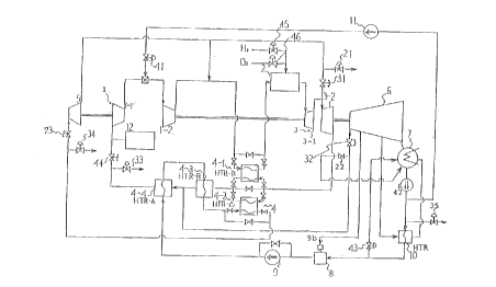
figures. Fig. 1 is a diagrammatic view of an entire hydrogen
burning turbine plant of one embodiment according to the
present invention. In Fig. 1, a compressor 1 consists of a low
pressure compressor 1-1 and a high pressure compressor 1-2 and
steam coming out of the high pressure compressor 1-2 flows
through a heat exchanger 4-1, enters a combustion chamber 2,
where oxygen and hydrogen as fuel are burned, to be heated to
become a high temperature steam of about 3,000~C and flows into
a turbine 3. The turbine 3 consists of a high temperature high
pressure turbine 3-1 and a high temperature low pressure
turbine 3-2. The high temperature high pressure turbine
- 20 -
CA 0224~470 1998-08-2~
3-1 is operated at about 1,700~C as steam flowing thereinto is
diluted by return steam at steady operation time and the high
temperature low pressure turbine 3-2 is driven by exhaust steam
of the high temperature high pressure turbine 3-1, and exhaust
steam of the high temperature low pressure turbine 3-2 gives
its exhaust heat to a condensed water at heat exchangers 4-
3, 4-4 and returns to the low pressure compressor 1-1. Thus,
a cycle is so constructed.
A portion of the steam coming out of the heat
exchanger 4-3 drives a low pressure turbine 6 and, after having
become a low temperature steam, flows through a heat exchanger
10 to give its heat to a condensed water and then enters a
condenser 7 to be condensed to water. On the other hand, the
steam which has driven the low pressure turbine 6 and has been
condensed to water flows into a deaerator 8 as it is.
A portion of the water from the condenser 7 is led
into the heat exchanger 10 by a pump 42 to be heated there and
enters the deaerator 8 to be joined with water coming from the
low pressure turbine 6 and deaerated and then flows through the
heat exchangers 4-4, 4-3 via a feedwater pump 9 and, a valve
being switched as the case may be, flows through a heat
exchanger 4-2 to be heated further and enters a high pressure
turbine 5.
A portion of the steam which has worked to drive the
high pressure turbine 5 joins with an outlet side steam of the
CA 0224~470 1998-08-2~
high pressure compressor 1-2 to give heat at the heat exchanger
4-1 and return to the combustion chamber 2, and the remaining
steam is sent to the high temperature low pressure turbine 3-2
to be used as a cooling steam thereof.
The water from the condenser 7 is carried by a pump
11 to an inlet side of the high pressure compressor 1-2 and is
sprayed by an intercooler spraying valve 41 into the steam
entering the high pressure compressor 1-2 so that the
temperature of the steam there is adjusted.
There are provided a governor valve 23 and a drain
valve 34 on the inlet side of the high pressure turbine 5, a
governor valve 31 and a drain valve 21 on the inlet side of the
high temperature low pressure turbine 3-2, a governor valve 32
and a drain valve 22 on the inlet side of the low pressure
turbine 6 and a shut-off valve 44 and a drain valve 33 on the
inlet side of the low pressure compressor 1-1, thereby flow
adjustment and drain discharge are effected respectively.
In the construction of the hydrogen burning turbine
plant as mentioned above, there is provided an auxiliary boiler
12 on the inlet side of the low pressure compressor 1-1, which
auxiliary boiler 12 is used at starting time of the plant.
Hydrogen andoxygenas fuelareburned inthecombustionchamber
2 and the high temperature steam of about 3,000~C is generated,
and if this steam of about 3,000~C flows as it is into the high
temperature high pressure turbine 3-1 at the starting time, it
- 22 -
CA 0224~470 1998-08-2~
is beyond an allowable temperature to be introduced into the
turbine, hence it is necessary that the steam is diluted to be
introduced into the turbine.
Thus, at the starting time, the auxiliary boiler 12
is operated so that a low temperature steam is fed to the inlet
side of the low pressure compressor 1-1 to be supplied further
to the combustion chamber 2 via the high pressure compressor
1-2 and the heat exchanger 4-1, and the high temperature steam
generated at the combustion chamber 2 is diluted to a
temperature below 3,000~C, to about 1,700~C for example, which
is allowable to be introduced into the high temperature high
pressure turbine 3-1 and is supplied into the high temperature
high pressure turbine 3-1 for operation.
That is, at the starting time, the auxiliary boiler
12 is operated and then the system having such a semi-closed
cycle as consisting of thecompressor 1, thecombustionchamber
2 and the heat exchanger 4 becomes operable by the steam
generated at the combustion chamber 2 itself, and once a steady
operation state comes, operation of the auxiliary boiler 12 is
stopped and the steady operation is continued by the steam
generated at the combustion chamber 2 itself.
It is to be noted that Fig. 1 shows an example where
the auxiliary boiler 12 is positioned to be connected to the
inlet side of the low pressure compressor 1-1 so as to supply
steam thereto and this example is appropriate for a case where
CA 0224~470 1998-08-2~
the steam generated at the auxiliary boiler 12 has a pressure
near the atmospheric pressure of 0.5 to 5 kg/cm2a and the
auxiliary boiler 12 having such a pressure range may be
connected midwayofthelowpressurecompressorl-landthe high
pressure compressor 1-2.
If the auxiliary boiler 12 has a capacity of
generating steam of a high pressure range of 5 to 100 kg/cm2a,
there being no need to make it further pressurized, the
auxiliary boiler 12 may be connected to an outlet of the high
pressure compressor 1-2 or to a casing surrounding the
combustion chamber 2.
According to the hydrogen burning turbine plant of
the embodiment described above, in the system for burning
hydrogen and oxygen to generate a high temperature steam for
thereby driving a turbine, sucha semi-closed cycle as consists
of passages of the compressor 1, the combustion chamber 2, the
turbine 2 and the heat exchanger 4 is constructed and the
auxiliary boiler 12 provided therein is operated at starting
time of the plant so that the high temperature steam is diluted
by the steam of the auxiliary boiler 12 for start and rise of
the operation, hence the start can be done smoothly and a start
system of the hydrogen burning turbine plant has been thus
established and practical use of the system has become
possible.
Fig. 2 is a diagrammatic view of a steam control
- 24 -
CA 0224~470 1998-08-2~
system of the hydrogen burning turbine plant described with
respect to Fig. 1. In Fig. 2, the drain valve 34 and a pressure
sensor Pl, a temperature sensor Tl and a moisture sensor Ml of
the steam areprovided at the inlet ofthe highpressureturbine
5. Likewise, the drain valve 33 and a pressure sensor P2, a
temperature sensor T2 and a moisture sensor M2Of the steam are
provided at the inlet of the compressor 1. Also provided are
the drain valve 22 and a pressure sensor P3, a temperature
sensor T3 and a moisture sensor M3 of the steam at the inlet
of the low pressure turbine 6 and further the drain valve 21
and a pressure sensor P4, a temperature sensor T4 and a moisture
sensor M4 ofthesteam at the outlet ofthe highpressureturbine
5.
Said drain valves 34, 33, 22, 21, pressure sensors
Pl to P4, temperature sensors Tl to T4 and moisture sensors M
to M4 are connected to a control unit 48-1 via A/D converters
47-1 to 47-4, respectively, and the control unit 48-1, being
inputted detected signals of the pressure sensors Plto P4, the
temperature sensors Tl to T4 and the moisture sensors Ml to M4
of respectivesystems viatheA/Dconverters47-lto47-4,sends
signals to open the drain valves 34, 33, 22, 21 to thereby
discharge the steam until such a steam condition of pressure,
temperature and moisture as to correspond to a normal operation
of the respective systems is attained and to close the
corresponding drain valves 34, 33, 22, 21 when the condition
- 25 -
CA 0224~470 1998-08-2~
is met, thus the drain valves are so controlled.
In the control unit 48-1, a dry steam condition
(pressure, temperature, moisture) of normal operation time is
stored for respective systems at the high pressure turbine 5
inlet, the compressor 1 inlet, the low pressure turbine 6 inlet
and the high pressure turbine 5 outlet. Setting of the
condition is inputted from an input unit 49-1 so as to be set
in a storage of the control unit 48-1, and valves so set may
be corrected as the case may be.
The control unit 48-1, upon start of the plant, takes
detected signals of the pressure sensors P1 to P4, the
temperature sensors Tl to T4 and the moisture sensors M1 to M4
of respective systems, compares whether or not the stored dry
steamcondition(pressure,temperature, moisture)required for
normal operation time is satisfied all for the respective
systems and, ifthecondition is notsatisfied, outputsasignal
to open the corresponding drain valves 34, 33, 22, 21 and, if
the condition is satisfied, outputs a signal to close the
corresponding drain valves.
It is to be noted that, in the above, an example where
the pressure sensors, temperature sensors, moisture sensors
and drain valves are provided at four places and the four drain
valves are controlled by the control unit has been described,
but the present invention is not limited thereto but the drain
valve to be controlled may be provided at necessary places or
CA 0224~470 1998-08-2~
inappropriatecombinationofvalvesaccordingto requirements,
plant characteristics, etc.
In the present embodiment, as mentioned above, the
auxiliary boiler is operated at starting time, the steam
generated at the combustion chamber 2 is diluted and then the
plant operation is started, but until the cycle becomes
self-sustained and thesteamcondition (pressure, temperature,
moisture) of the respective systems is established, if a wet
steam which does not satisfy the steam condition enters the
compressor or turbine, there is a risk of breakage thereof.
Byperformingthecontrolas describedabove, however,
at starting time of the plant, the drain valve corresponding
to the system which does not satisfy the steam condition is
openedso that thesteam is discharged outsideand, ifthesteam
condition is satisfied, the drain valve is closed, and a steady
operation is realized. Thus, a safe and secure starting is
carried out.
Intheabove, an exampleofusingthepressuresensors
Pl to P4, temperature sensors T1 to T4 and moisture sensors M
to M4 has been described, but the moisture sensor may not
necessarily be provided and if the pressure sensor and the
temperature sensor are provided, function of the present
invention may be attained such that pressure and temperature
are measured, steam condition is set and the drain valves 34,
33, 22, 21 are controlled by the control unit 48-1. by use of
- 27 -
CA 0224~470 1998-08-2~
the moisture sensors Ml to M4, however, the present invention
may be realized with a higher accuracy.
Fig. 3 is a diagrammatic view of control of flow
control valves of the hydrogen burning turbine plant of the
embodiment of Fig. 1. In Fig. 3, there are provided a governor
valve 23 on the inlet side of the high pressure turbine, a
rotation control unit 9a of the feedwater pump 9 in the flow
passage on the inlet side of the high pressure turbine 5 and
a bypass valve 9b disposed in parallel with the feedwater pump
9, and control lines of these units are connected to a control
unit 48-2.
Also, there are provided a variable blade drive unit
147 for the compressor 1, stationary blades thereof being
variable blades partially,a governorvalve32onthe inlet side
of the low pressure turbine 6 and a hydrogen supply valve 45
and an oxygen supply valve 46 of fuel to be supplied into the
combustion chamber 2 and control lines of these valves are
connected to the control unit 48-2. Also connected to the
control unit 48-2 via an A/D converter 47-5 is a temperature
sensor T for measuring steam temperature at the outlet of the
high temperature high pressure turbine 3-1 of the turbine 3.
Further, there is provided a governor valve 31 in
a passage of steam, extracted from return steam of the high
pressure turbine 5, for cooling blades of the turbine 3, and
a control line thereof is connected to the control unit
CA 0224~470 l998-08-2
48-2.
Inthecontrolsystemsconstructedas mentionedabove,
the control unit 48-2 controls the variable blade drive unit
147 SO astodriverotativelythevariableblades,saidvariable
blades being portion of thestationary blades ofthecompressor
1 and each thereof being constructed to rotate around one point
as center on a blade chord so as to make flow rate therethrough
variable. The control is done such that characteristics of the
rotational angle of the variable blades and the steam pressure
at the compressor 1 outlet in relation to the flow rate are
stored in advance in the control unit 48-2 and, in accordance
with the steam flow rate and pressure condition set in an input
unit 49-2, the control unit 48-2 controls the variable blade
drive unit 147 SO as to set the angle of the variable blades.
Also, the control unit 48-2 controls the governor
valve 23 at the high pressure turbine 5 inlet so that outlet
steam pressure of the high pressure turbine 5 is controlled.
The control is done such that characteristics of the opening
of the governor valve and the outlet steam pressure of the high
2 0 pressure turbine 5 are stored in advance in the control unit
48-2 and, in accordance with the high pressure turbine
operationcondition set inthe input unit 49-2, thecontrolunit
48-2 controls the opening of the governor valve 23 SO that the
outlet steam pressure at the high pressure turbine 5 is
controlled. Also, the control unit 48-2 controls rotations of
- 29 -
CA 0224~470 1998-08-2~
the feedwater pump 9 via the rotation control unit 9a or
controls opening of the bypass valve 9b so that the steam flow
rate of the high pressure turbine 5 is controlled in accordance
with the condition set in advance.
Also, the control unit 48-2 controls the governor
valve 32 at the low pressure turbine 6 inlet so that the inlet
steam pressure and flow rate of the low pressure turbine 6 are
controlled, and the control unit 48-2 controls the governor
valve 31 of the blade cooling steam flowing into the high
temperature high pressure turbine 3-1 and the high temperature
low pressure turbine 3-2 of the turbine 3 so that the flow rate
and pressure of the steam returning from the high temperature
high pressure turbine 3-1 and the high temperature low pressure
turbine 3-2 to the compressor 1 are controlled. These controls
aredonealso, likethosementionedabove,suchthattheopening
of the respective governor valves is controlled in accordance
with the condition set in advance in the control unit 48-2.
Further, the control unit 48-2 controls the hydrogen
supply valve 45 and the oxygen supply valve 46 of the fuel of
hydrogen and oxygen to be supplied into the combustion chamber
2. In the control unit 48-2, characteristics of control
temperature at the high temperature high pressure turbine 3-1
inlet inrelationto fuelratio, flow rate,openingofthevalve,
etc. are set and stored in advance, and the control unit 48-2
is inputted a signal of the temperature sensor T provided at
- 30 -
CA 0224~470 1998-08-2~
the outlet of the turbine 3 or midway therein and, while
watching this detected signal, controls the opening of the
hydrogen supply valve 45 and the oxygen supply valve 46 in
accordance with the set condition so as not to exceed the set
temperature.
It is to be noted that, in the above, an example where
the control is done such that the entire system of the high
pressure turbine 5 inlet, the variable blades of thecompressor
1, thelow pressureturbine 6 inlet, the turbine 3 coolingsteam
inlet and the combustion chamber 2 is controlled by the control
unit 48-2 has been described, but the present invention is not
necessarily limited thereto but the control unit may be
selected so that eachofthe systems is controlled individually
or combination of necessary systems only is controlled
according to requirements, plant characteristics, etc.
Fig. 4 is a diagrammatic view of a hydrogen burning
turbine plant of another embodiment according to the present
invention. In Fig. 4, same reference numerals as those in Fig.
6 of the prior art plant designate same or similar construction
parts. The present embodiment is featured in that a recovery
type cooling steam system is added to the cooling system of the
first turbine 105 such that, in addition to the first turbine
cooling steam 119 of the prior art, a first turbine recovery
type cooling steam 120 is extracted from an outlet of the third
turbine 110 to be introduced into the first turbine 105 for
CA 0224~470 1998-08-2~
cooling thereof and the steam used for cooling is mixed into
an outlet steam of the heat exchanger 103 (inlet steam of the
combustor 104).
Examples of cycle calculations in the hydrogen
burning turbine plant are shown in Table 1 with respect to the
present invention and in Table 2 with respect to the prior art.
In Tables 1 and 2, flow rate, temperature and pressure at
respective positions shown by reference numerals 201 to 245 in
Fig. 4 and Fig. 7, which figure is same as Fig. 6, are shown,
wherein Fig. 4 includes reference numerals 201 to 224 and Fig.
7 includes reference numerals 225 to 245.
As understood from Tables 1 and 2, while in the
present invention the total value of the cooling medium
proportion of the first turbine increases from 0.15 to 0.172
as compared with the prior art, 0.109 out of said 0.172 is
replaced by the recovery type cooling steam and the value of
the cooling steam mixing into the gas path of the first turbine
reduces from 0.15 (prior art) to 0.063 (present invention),
thereby there is obtained an effect that the gross thermal
efficiency increases from 60.3% to 61.0% with relative
enhancement of 1.2%, using presumptions of calculation shown
in Table 3.
That is, if the usual cooling system using the first
turbine cooling steam 119 and the recovery type cooling system
using the first turbine recovery type cooling steam 120 are
- 32 -
CA 0224~470 1998-08-2~
compared with each other, there is an advantage in the recovery
type cooling system that temperature lowering of the fluid in
the gas pathdueto mixingofthecoolingmedium intotheturbine
gas path and pressure loss due to mixing of the cooling medium
and the fluid in the gas path are eliminated and there is
obtained an effect that the turbine output lowering due to the
cooling is mitigated. Also, the heat obtained from the turbine
by the recovery type cooling is recovered upstream of the
combustor, thereby fuel flow rate can be reduced, which is also
one reason for enhancing the gross thermal efficiency.
- 33 -
CA 0224~470 l998-08-2
Ta~le 1
Refer- Flow Temper- First turbine
ence rate ature Pressure inlet temperature: 1700CC
numeral (kg/s) t~C) (10 Pa) Cooling medium proportion =
Nos. First turbine cooling steam
201237 1700 45.1 (0.063) + First turbine
recovery type cooling
202252 756 1.2 steam(0.109) = 0.172
203252 528 1.1
204116 235 1.1 Items Output
205116 105 1.0 (MW)
206116 234 3.1 Low pressure compressor 28.9
207125 139 3.1 High pressure compressor 101.6
208125 550 50.0 First turbine 543.6
209186 700 47.5 Second turbine 63.7
210 75 82 408 Third turbine 36.0
211 75 177 388 Machine loss 5.1
212 75 473 368 Generator loss 7.6
213 75 593 350 Total output 500
214 75 291 50
Gross therm~l effic;e~cy 61.0%
215136 235 1.1 (~V reference)
216130 33 0.05
217130 33 1.2
218 75 77 1.0
219 9 33 1.2
220 9 33 3.1
221 15 269 34.1
222 26 291 50.0
223 26 291 50.0
224160 716 47.5
- 34 -
CA 0224~470 l998-08-2
Table 2
Refer- Flow Temper- First turbine
ence rate ature Pressure inlet temperature: 1700~C
numeral (kg/s) (~C) (lOsPa) Cooling medium
Nos. proportion = 0.15
225237 1700 45.1
2276272 526 1.12 ItemsOutput
228134 300 1.1 Low pressure compressor 34.5
229138 105 1.0 High pressure compressor 121.1
230138 234 3.1 First turbine 563.8
231149 140 3.1 Second turbine 70.5
232149 550 50.0 Third turbine 34.0
233185 682 47.5 Machine loss 5.1
234 71 70 408 Generator loss 7.6
235 71 248 388 Total output 500
236 71 486 368
239 71 593 350 Gross therm~1 efficiency 60.3
(~V reference)
238 71 291 50
237134 300 1.1
240130 33 0.05
241130 35 0.3
242 72 70 0.3
243 11 35 1.0
244 11 35 3.1
245 36 269 34.1
CA 0224~470 1998-08-2
Table 3
Compressor adiabatic efficiency 0.89
Turbine adiabatic efficiency 0.93
Combustor combustion efficiency 1.0
Combustor pressure loss 5% of inlet pressure
Pump work disregarded
Machine efficiency 0.99
Generator efficiency 0.985
First turbine inlet temperature (~C) 1700
0.15 of the first
Cooling medium proportion turbine inlet flow
rate
Third turbine inlet pressure (lOsPa) 350
Third turbine inlet temperature (~C) 593
It is understood that the invention is not limited
to the particular construction and arrangement herein
illustrated and described but embraces such modified forms
thereof as come within the scope of the following claims.
- 36 -