Language selection

Search

Patent 2245753 Summary

Third-party information liability

Some of the information on this Web page has been provided by external sources. The Government of Canada is not responsible for the accuracy, reliability or currency of the information supplied by external sources. Users wishing to rely upon this information should consult directly with the source of the information. Content provided by external sources is not subject to official languages, privacy and accessibility requirements.

Claims and Abstract availability

Any discrepancies in the text and image of the Claims and Abstract are due to differing posting times. Text of the Claims and Abstract are posted:

  • At the time the application is open to public inspection;
  • At the time of issue of the patent (grant).
(12) Patent: (11) CA 2245753
(54) English Title: QUICK RELEASE BOW-TO-CABLE CONNECTOR FOR A COVERING SYSTEM
(54) French Title: CONNECTEUR RAPIDE ARCEAU-CABLE POUR SYSTEME DE RECOUVREMENT
Status: Expired
Bibliographic Data
(51) International Patent Classification (IPC):
  • B60P 7/04 (2006.01)
  • B60P 7/02 (2006.01)
(72) Inventors :
  • BREWER, ROBERT RAY (United States of America)
  • SWANSON, BRADFORD PAUL (United States of America)
(73) Owners :
  • SHUR-CO, LLC (United States of America)
(71) Applicants :
  • SHUR COMPANY (United States of America)
(74) Agent: RIDOUT & MAYBEE LLP
(74) Associate agent:
(45) Issued: 2002-03-05
(22) Filed Date: 1998-08-25
(41) Open to Public Inspection: 1999-02-26
Examination requested: 1998-08-25
Availability of licence: N/A
(25) Language of filing: English

Patent Cooperation Treaty (PCT): No

(30) Application Priority Data:
Application No. Country/Territory Date
08/920,093 United States of America 1997-08-26

Abstracts

English Abstract


A connector is provided between a bow end and a
cable system that moves the bow across the opening of a
container or truck box. One end of the connector is adapted
to mate with the end of the bow. The other end of the
connector has a bore through which the cable passes. A first
open slot in the connector communicates with the bore and is
oriented transversely of the bore. A second open slot
extending through a first side of the connector communicates
with both the bore and the first open slot and opens in a
first direction relative to the connector. A third open slot
extending through a side of the connector opposite the first
side communicates with both the bore and the first open slot
and opens in a second direction relative to the first
direction. The connector may be conveniently attached to the
cable by passing the cable through the first slot into
transverse alignment with the bore to the point where it is
parallel to the transverse slots. Subsequent lateral
rotation of the connector allows the cable to simultaneously
pass through the second and third slots and to become
longitudinally aligned within the bore. Because the
subsequent mating of the bow end with the opposite end of the
connector restricts lateral rotation in the opposite
direction, movement of the connector in a direction other
than along the cable is prevented. This construction permits
the connector and associated bow to be readily removed and
re-attached to the cable without disassembly of the cable
system.


French Abstract

Connecteur fourni entre l'extrémité d'un arceau et un système de câbles qui déplace l'arceau à travers l'ouverture d'un conteneur ou d'une caisse de camion. Une extrémité du connecteur est adaptée pour se raccorder à l'extrémité de l'arceau. L'autre extrémité du connecteur a un alésage dans lequel passe le câble. Une première fente ouverte dans le connecteur communique avec l'alésage et est orientée transversalement vers l'alésage. Une deuxième fente ouverte se prolongeant à travers le premier côté du connecteur communique à la fois avec l'alésage et la première fente ouverte et s'ouvre dans une première direction en rapport au connecteur. Une troisième fente ouverte se prolongeant à travers un côté du connecteur à l'opposé du premier côté communique à la fois avec l'alésage et la première fente ouverte et s'ouvre dans une deuxième direction en rapport à la première direction. Le connecteur peut être fixé au câble sans inconvénient en passant le câble à travers la première fente dans l'alignement transversal à l'alésage au point où il est parallèle aux fentes transversales. Une rotation latérale ultérieure du connecteur permet au câble de passer simultanément à travers les deuxième et troisième fentes et de s'aligner longitudinalement à l'alésage. Puisque le raccord ultérieur de l'extrémité de l'arceau avec l'extrémité opposée du connecteur restreint la rotation latérale dans la direction opposée, le déplacement du connecteur en une direction autre que le long du câble est ainsi empêché. Cet assemblage permet d'enlever facilement le connecteur et l'arceau connexe et de les fixer à nouveau au câble sans défaire le système de câbles.

Claims

Note: Claims are shown in the official language in which they were submitted.


- 11 -
WHAT IS CLAIMED IS:

1. A bow-to-cable connector for an accordion-style
system covering the top opening of a container or
vehicle, the system including a covering supported by bows
that are moved between an open and closed position by cables,
each bow having two ends, the bow spanning between the sides
of the opening, the connector comprising:
a first portion adapted to engage a bow
end, the first portion having a side adapted for slidable
movement along the sides of the opening while maintaining
said bow in spanning relationship across the width of said
container; and
a second portion containing a bore
therethrough for slidable engagement with the cable, the bore
communicating with slots, said slots configured to allow
removal of said connector from cable when the first portion
is disengaged from the bow end and upon manual rotation of
said connector relative to said cable.


2. The connector of claim 1 wherein the side
of the first portion is a planar bearing surface.


3. The connector of claim 2 wherein the
second portion projects and extends downwardly from said
planar bearing surface when said connector is supported on
the side of the opening.


- 12 -
4. The connector of claim 1 wherein the slots
comprise a first open slot in communication with said through
bore and oriented transversely of said through bore, a second
open slot in communication with both said through bore and
said first open slot extending through a first side of said
connector and open in a first direction relative to said
connector, and a third open slot in communication with both
said through bore and said first open slot extending through
a side of said connector opposite said first side and open in
a second direction relative to said first direction.


5. The connector of claim 4 wherein said
connector is installed on said cable by passing said cable
through said first slot into transverse alignment with said
through bore, then rotating said connector such that said
cable simultaneously passes through said second and third
slots and becomes longitudinally aligned within said through
bore.


6. The connector of claim 1 wherein the first
portion and second portion are approximately perpendicular to
one another.

7. A system for covering an open top of a
container comprising:
a plurality of parallel spaced bows each having
opposed free ends;


- 13 -

a connector attached to each free end of each
bow, said connector having a bearing surface for slidably
supporting each bow on opposed upper rails of the container;
a flexible cover attached to said bows at
spaced intervals along said cover;
a pair of pulleys journaled for rotation on
opposite sides of the container, said pairs of pulleys each
supporting and endless cable for translational movement
parallel and in closely spaced relation to said rails;
a through bore through each connector for
receiving one of said cables and configured to permit said
connectors and associated bows to move translationally along
said cables and said rails;
means for rotating said pulleys;
means for fixedly securing the connectors of
one bow to said cables; and
slot means communicating with the through bore
of each connector and being configured to permit manual
removal of said connector from said cable upon rotational
movement of said connectors relative to said cable.

8. The system of claim 7 wherein said slot
means comprises a first open slot in communication with said
through bore and oriented transversely of said through bore,
a second open slot in communication with both said through
bore and said first open slot extending through a first side
of said connector and open in a first direction relative to


-14-

said connector, and a third open slot in communication with
both said through bore and said first open slot extending
through a side of said connector opposite said first side and
open in a second direction relative to said first direction.


9. The system of claim 8 wherein said
connector is installed on said cable by passing said cable
through said first slot into transverse alignment with said
through bore, then rotating said connector such that said
cable simultaneously passes through said second and third
slots and becomes longitudinally aligned within said through
bore.


10. A trailer for hauling aggregates, asphalt,
gravel, foodstuffs or other material having a body assembly
with an open top and a cover system for selectively covering
said open top, the cover system comprising:
a plurality of parallel spaced bows each having
opposed free ends;
a connector attached to each free end of each
bow, said connector having a bearing surface for slidably
supporting each bow on opposed upper rails of the container;
a flexible cover attached to said bows at
spaced intervals along said cover;
a pair of pulleys journaled for rotation on
opposite sides of the container, said pairs of pulleys each


-15-

supporting and endless cable for translational movement
parallel and in closely spaced relation to said rails;
a through bore through each connector for
receiving one of said cables and configured to permit said
connectors and associated bows to move translationally along
said cables and said rails;
means for rotating said pulleys;
means for fixedly securing the connectors of
one bow to said cables; and
slot means communicating with the through bore
of each connector and being configured to permit manual
removal of said connector from said cable upon rotational
movement of said connectors relative to said cable.


11. The trailer of claim 10 wherein said slot
means comprises a first open slot in communication with said
through bore and oriented transversely of said through bore,
a second open slot in communication with both said through
bore and said first open slot extending through a first side
of said connector and open in a first direction relative to
said connector, and a third open slot in communication with
both said through bore and said first open slot extending
through a side of said connector opposite said first side and
open in a second direction relative to said first direction.


12. The trailer of claim 11 wherein said
connector is installed on said cable by passing said cable


-16-

through said first slot into transverse alignment with said
through bore, then rotating said connector such that said
cable simultaneously passes through said second and third
slots and becomes longitudinally aligned within said through
bore.


13. A method of attaching a bow to a cable,
the bow being of type for supporting a retractable tarpaulin
cover over a box container, the method comprising the steps
of:
providing a connector for attachment of a bow
to a cable, said connector having means for connection to
said bow and being provided with a through bore through which
a cable passes;
providing slot means in said connector in
communication with said bore, said slot means being
configured to receive said cable and allow said cable to pass
into said bore only upon rotation of said connector relative
to said cable;
inserting said cable into said slot means; and
rotating said connector relative to said cable
whereupon said cable passes into said bore.


14. The method of claim 13 wherein said slot
means comprising a first open slot in communication with said
through bore and oriented transversely of said through bore,
a second open slot in communication with both said through


- 17 -

bore and said first open slot extending through a first side
of said connector and open in a first direction relative to
said connector, and a third open slot in communication with
both said through bore and said first open slot extending
through a side of said connector opposite said first side and
open in a second direction relative to said first direction.


15. The method of claim 14 wherein said
connector is attached to said cable by passing said cable
through said first slot into transverse alignment with said
through bore, then rotating said connector such that said
cable simultaneously passes through said second and third
slots and becomes longitudinally aligned within said through
bore.


Description

Note: Descriptions are shown in the official language in which they were submitted.


CA 0224~7~3 1998-08-2~


TITLE OF THE INVENTION

QUICK Rr~lr~A~E BOW-TO-CABLE CONNECTOR FOR A COVERING SYSTEM

BACKGROUND OF THE I~v~NllON

1. Field of the Invention
The present invention relates generally to
systems for covering open top vehicles or containers and more
particularly to the interconnection between bows that support
such coverings and cables that move the bows.

2. Description of the Prior Art
It is desirable to use tarpaulins or other
coverings on grain hauling trucks and dump trucks. The
tarpaulins serve not only to shelter the container contents
against the elements, but also to maintain the contents in
the container during high speed transportation.
A number of systems exist for covering truck
and trailer containers with tarpaulins such that the
tarpaulins may be extended from an open position, exposing
the interior of the container, to a closed position covering
the container. Typically, these systems involve the use of
metal bows that span the width of the opening to support the
tarpaulin at parallel spaced intervals. For some
applications, it is desirable to provide a system wherein

CA 0224~7~3 1998-08-2~


the bows are at least partially displaceable from over the
opening to provide greater access to the container interior.
One such system is disclosed in U.S. Patent No. 5,487,584,
issued to Jespersen. In that system, the tarpaulin rolls up
lengthwise along a side of the container and the bows, joined
by a ridgepole, pivot at least partially out the way of the
container opening.
Another design, which we will refer to as the
"accordion-style tarp system," employs a plurality of
parallel spaced bows to which the tarpaulin is fastened. The
ends of the bows are attached to a cable arrangement running
lengthwise on both sides of the container. Operation of the
cables acts to slide the bow ends along upper side rails of
the container such that the tarpaulin may be moved in
accordion fashion between the open and closed positions. The
cable in this system can be supported on pulleys which, when
actuated by a crank, draw a lead bow across the container
opening with the other bows passively drawn by the tarpaulin
attached between the bows. The operation is much the same as
that of a typical curtain rod.
The cable of the accordion-style tarp system is
threaded through the bow ends. Should a bow become damaged
and require replacement, the entire cable must be unthreaded
from the bow ends and adjacent bows and rethreaded through a
new bow. This disassembly necessarily involves significant
manual labor and consequent downtime of the vehicle
equipment.


CA 0224~7~3 1998-08-2~


Accordingly, it is an object of the present
invention to provide a connector between the bow end and the
cable that allows removal and replacement of the bow without
unthreading and rethreading of the cable. Further, it is an
object of the invention to provide such a connector that is
capable of being adjusted to various widths of trailers, can
be manufactured as a single piece, and is readily molded in a
cost effective manner.


SUMMARY OF THE lNv~NllON


The present invention provides an improved
connector between a bow end and a cable system that moves the
bow across the opening of a container or truck box. One end
of the connector is adapted to mate with the end of the bow.
The other end of the connector has a bore through which the
cable passes. A first open slot in the connector
communicates with the bore and is oriented transversely of
the bore. A second open slot extending through a first side
of the connector communicates with both the bore and the
first open slot and opens in a first direction relative to
the connector. A third open slot extending through a side of
the connector opposite the first side communicates with both
the bore and the first open slot and opens in a second

direction relative to the first direction.
The connector may be conveniently attached
to the cable by passing the cable through the first slot into

CA 0224~7~3 1998-08-2~


transverse alignment with the bore to the point where it is
parallel to the transverse slots. Subsequent lateral
rotation of the connector allows the cable to simultaneously
pass through the second and third slots and to become
longitudinally aligned within the bore. Because the
subsequent mating of the bow end with the opposite end of the
connector restricts lateral rotation in the opposite
direction, movement of the connector in a direction other
than along the cable is prevented. This construction permits
the connector and associated bow to be readily removed and
re-attached to the cable without disassembly of the cable
system.


BRIEF DESCRIPTION OF THE DRAWINGS


The foregoing and other novel features and
advantages of the invention will be better understood in
light of the following detailed description and accompanying
drawings, wherein:
FIG. 1 is a front side perspective view of a
truck trailer having a container covered by a tarpaulin in
accordance with the invention;
FIG. 2 is a partial cross-sectional view of the
covered container taken substantially along the line 2-2 of

FIG. 1;


CA 0224~7~3 1998-08-2~


FIG. 3 is a front side perspective view of a
truck trailer showing the tarpaulin retracted from over the
container;
FIG. 4 is a detail view of a bow-to-cable
connector as installed in accordance with the invention;
FIG. 5 is an end view of the bow-to-cable
connector illustrating an initial alignment in preparation of
installation on a support cable;
FIG. 6 is a side view of the bow-to-cable
connector illustrating the beginning of a first second stage
in its installation on a support cable;
FIG. 7 is a view of the bow-to-cable connector
end opposite the view of FIG. 5 illustrating the conclusion
of the first stage in the installation of the connector on a
support cable;
FIG. 8 is a cross-sectional view taken along
the line 8-8 of FIG. 7;
FIG. 9 is a cross-sectional view similar to
FIG. 8 illustrating the connector after the second, lateral
rotation stage of installation on the cable;
FIG. 10 is a partial side perspective view
showing the cover as retracted from over the trailer
container; and
FIG. 11 is a partial perspective view

illustrating the attachment method for the rearward most
connectors.


CA 0224~7~3 1998-08-2~


DETAILED DESCRIPTION OF THE PREFERRED EMBODIMENTS


Referring now to the drawings and initially to
FIG. 1, a truck trailer is designated generally by the
reference numeral 10 and includes as a principal component an
open top container or box 12. The illustrated truck trailer
10 is of a type particularly suitable for hauling asphalt,
aggregate, or the like. However, the present invention is
not limited to such a truck trailer and may also be used
advantageously on grain trailers, dump truck boxes or refuse
hauling containers, for example, or stationary open top
containers. The container 12 is shown in FIG. 1 as being
covered by a tarpaulin 14 extended over its open top.
The tarpaulin may be fabricated from a variety of suitable
materials such as an open weave mesh or vinyl. FIG. 2 shows
the tarpaulin 14 attached by suitable fasteners 16 to bows 18
extending across the width of the container 12. The bows 18
are, in turn, attached at their opposite ends to bow-to-cable
connectors 20 which will be described in detail hereinafter.
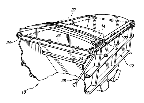
Turning now to FIG. 3, the tarpaulin 14 is
shown in the open position over the top of container 12

exposing the interior of the container. The system for
retracting the tarpaulin includes continuous cables 22
supported on pulleys 24 on opposite upper sides of the
container 12. A shaft 26 connects the pair of forward
pulleys 24; one pulley 24 is provided with a crank lever 28
and associated universal joint 29. The connectors 20, as

CA 0224~7~3 1998-08-2~


best seen in FIG. 4, are threaded on the cables 22 as to
slide freely thereon, except for the two connectors 23 (only
one shown in Figs.) associated with the rearward bow which
are fixed to the cables 22 as described below (see FIG. 10).
By this arrangement, an operator can manually turn the crank
lever 28 causing the cables 22 to rotate about the pulleys.
This action pulls the connectors 23 associated with the
rearward-most connectors toward the front of the container 12
compressing the tarpaulin 14 and associated free bows 18 in
accordion fashion into a retracted or open position at the
front of the container 12.
Details of the connector 20 can be seen in FIG.
4. The connector 20 is generally L-shaped having
a downwardly projecting leg portion 30 and a laterally
projecting portion 32. The laterally projecting portion 32
is provided with a cylindrical, blind bore 34 adapted in
depth and cross-section to receive and mate with a bow
end 18. The bow 18 is rigidly attached to the connector 20
by one or more screws or bolts 36. The bore 34 has
sufficient depth to allow for receipt of and attachment to
bows 18 and to be adjustable for varying widths of trailers.
The laterally projecting portion 32 is provided with a
generally planar lower, relatively low friction surface 38 to
freely slide on an upper rail 40 of the container 12.
Molding the inventive connector of a hard plastic will
accomplish a suitable friction surface. The bow end 18 is
supported by the connector 20 such that the bow 18 is in a


CA 0224~7~3 1998-08-2~


generally upright position when viewed from the side. The
tarpaulin 14 may be secured to the connector 20 by a suitable
screw 42.
In accordance with the invention, and as best
seen in FIGS. 5-9, the connector 20 is designed to be
attachable to the cable 22 without any removal of the cable
22 system from the container 12. To this end, the connector
20 is provided with a through bore 44 through which the cable
22 freely passes when the connector 20 is installed on the
cable 22. However, an open slot 46 is formed in the
projecting portion 30 running longitudinally of the connector
20 and in communication with the through bore 44. Also,
extending laterally through a first side of the projecting
portion 30 into communication with both the slot 46 and the
bore 44 is a second open slot 48. Further, extending
laterally through a second side of the projecting portion 30
into communication with both the slot 46 and bore 44 is a
third open slot 50. By this arrangement of the slots 46, 48
and 50, together with the through bore 44, the connector 20
may be readily installed on the cable 22 by guiding the cable
22 first into the longitudinal slot 46 (see FIGS. 5-8) until
the cable 22 is in transverse alignment with the bore 44.
Then the connector 20 may be rotated through ninety degrees
whereupon the cable passes through both slots 48 and 50
simultaneously and becomes trapped within the bore 44 ready
for use. Only reverse lateral rotation will allow any
movement other than slidable movement along the cable. Such


CA 0224~7~3 1998-08-2~


reverse rotation will be prevented when the bow end 18 is
mated with bore 34.
FIG. 10 shows further details of the system
illustrating a plurality of connectors 20 moved to a stored
position. A rearward most connector 23 is shown in FIG. 11
as locked longitudinally of the cable 22 by a pair of opposed
cable clamps 54. The clamps 54 are of a common type
including U-bolts 56 and cooperating plates 58 which are
tightened onto the cable 22 by suitable nuts 60. In a
preferred form, the rearward most connectors 23 are provided
with transverse stabilizing pins 62 extending parallel to the
cables 22, and the cable clamps 54 are dimensioned to clamp
over both the pins 62 and the cables 22 simultaneously.
It is contemplated that a tarp system using the
inventive bow-to-cable connector also may use wind guards.
Wind guards can be attached to the bow connectors (through
the tarpaulin) to mate with an appropriately located
anchor(s) on the side of the box when the system is in the
closed position. Such wind guards are conventional, have
been known in the art for fifteen years or more, and can be
adapted to work with a system using the inventive bow
connectors by those ordinarily skilled in the art.
It can now be appreciated that a bow-to-cable
connector 20 in accordance with the invention offers
considerable advantages over the prior art. Should a bow 18
or connector 20 become damaged in use, the bow end 18 is
simply slid out of the bore 34 of the connector 20. This


CA 0224~7~3 1998-08-2~


- 10 -

leaves the connector 20 free to be rotated relative to the
cable 22 whereupon the cable 22 simply passes out of the slot
46 and the connector 20 is completely released.
Reinstallation of the connector 20 is readily accomplished in
reverse manner. Thus, the manual labor involved in
disassembling the cable 22 system and unthreading and
rethreading connectors is completed avoided. While other
means could be used to provide a detachable connector, such
as brackets and screws, for example, the present connector 20
may be readily molded as a single part from suitable plastic
and requires no auxiliary hardware or moving parts to detach
it and re-attach it about the cable. Plastic is desirable
also as it can provide a low friction surface for the
connector's contact with the side rail. Accordingly, the
connector 20 is highly cost effective and convenient to
manufacture while also being sturdy in construction to have
relatively long life.
While the present invention has been described
in connection with a preferred embodiment thereof, it will be
apparent to those skilled in the art that many changes and
modifications may be made without departing from the true
spirit and scope of the present invention. Accordingly, it
is intended by the appended claims to cover all such changes
and modifications as come within the spirit and scope of the
invention.

Representative Drawing
A single figure which represents the drawing illustrating the invention.
Administrative Status

For a clearer understanding of the status of the application/patent presented on this page, the site Disclaimer , as well as the definitions for Patent , Administrative Status , Maintenance Fee  and Payment History  should be consulted.

Administrative Status

Title Date
Forecasted Issue Date 2002-03-05
(22) Filed 1998-08-25
Examination Requested 1998-08-25
(41) Open to Public Inspection 1999-02-26
(45) Issued 2002-03-05
Expired 2018-08-27

Abandonment History

There is no abandonment history.

Payment History

Fee Type Anniversary Year Due Date Amount Paid Paid Date
Request for Examination $400.00 1998-08-25
Registration of a document - section 124 $100.00 1998-08-25
Application Fee $300.00 1998-08-25
Maintenance Fee - Application - New Act 2 2000-08-25 $100.00 2000-08-25
Maintenance Fee - Application - New Act 3 2001-08-27 $100.00 2001-08-21
Final Fee $300.00 2001-12-13
Maintenance Fee - Patent - New Act 4 2002-08-26 $100.00 2002-08-02
Maintenance Fee - Patent - New Act 5 2003-08-25 $150.00 2003-08-21
Maintenance Fee - Patent - New Act 6 2004-08-25 $200.00 2004-07-19
Maintenance Fee - Patent - New Act 7 2005-08-25 $200.00 2005-08-04
Maintenance Fee - Patent - New Act 8 2006-08-25 $200.00 2006-07-05
Maintenance Fee - Patent - New Act 9 2007-08-27 $200.00 2007-07-16
Maintenance Fee - Patent - New Act 10 2008-08-25 $250.00 2008-07-10
Maintenance Fee - Patent - New Act 11 2009-08-25 $250.00 2009-08-20
Maintenance Fee - Patent - New Act 12 2010-08-25 $250.00 2010-08-24
Maintenance Fee - Patent - New Act 13 2011-08-25 $250.00 2011-08-25
Maintenance Fee - Patent - New Act 14 2012-08-27 $250.00 2012-07-19
Maintenance Fee - Patent - New Act 15 2013-08-26 $450.00 2013-08-15
Maintenance Fee - Patent - New Act 16 2014-08-25 $450.00 2014-02-27
Maintenance Fee - Patent - New Act 17 2015-08-25 $450.00 2015-07-29
Registration of a document - section 124 $100.00 2015-10-23
Maintenance Fee - Patent - New Act 18 2016-08-25 $450.00 2016-08-04
Maintenance Fee - Patent - New Act 19 2017-08-25 $450.00 2017-08-02
Owners on Record

Note: Records showing the ownership history in alphabetical order.

Current Owners on Record
SHUR-CO, LLC
Past Owners on Record
BREWER, ROBERT RAY
SHORMA COMPANY
SHUR COMPANY
SWANSON, BRADFORD PAUL
Past Owners that do not appear in the "Owners on Record" listing will appear in other documentation within the application.
Documents

To view selected files, please enter reCAPTCHA code :


To view images, click a link in the Document Description column. To download the documents, select one or more checkboxes in the first column and then click the "Download Selected in PDF format (Zip Archive)" or the "Download Selected as Single PDF" button.

List of published and non-published patent-specific documents on the CPD .

If you have any difficulty accessing content, you can call the Client Service Centre at 1-866-997-1936 or send them an e-mail at CIPO Client Service Centre.


Document
Description 
Date
(yyyy-mm-dd) 
Number of pages   Size of Image (KB) 
Cover Page 1999-03-18 2 102
Drawings 2001-03-27 3 120
Abstract 1998-08-25 1 38
Description 1998-08-25 10 336
Claims 1998-08-25 7 204
Drawings 1998-08-25 3 106
Cover Page 2002-01-29 1 60
Representative Drawing 2002-01-29 1 24
Representative Drawing 1999-03-18 1 23
Fees 2001-08-21 1 33
Fees 2000-08-25 1 32
Correspondence 2001-12-13 1 36
Assignment 1998-08-25 8 323
Prosecution-Amendment 2001-03-27 4 161
Fees 2009-08-20 1 35
Fees 2010-08-24 1 37