Note: Descriptions are shown in the official language in which they were submitted.
CA 0224~819 1998-08-10
DESCRIPTION
WATER BED TYPE MASSAGING MACHINE
TECHNICAL BACKGROUND
The present invention relates to a water bed type massaging
machine so adapted as to massage the body of a person. More
particularly, the present invention rèlates to a water bed type
massaging machine with a water bed filled with water or hot
water, so designed as to enable massaging the entire body of a
person lying on the water bed.
BACKGROUND TECHNOLOGY
Hitherto, International Application No. PCT/US90/03505
(International Publication No. WO90/15585) discloses a massaging
machine of a bed type which can massage the entire body of a
person.
This massaging machine includes a housing constituting a
massaging chamber within the interior thereof with its top side
open, a flexible sheet disposed on the open top side of the
housing for supporting a person lying thereon, a fluid jet
apparatus disposed in the massaging chamber for blowing jet
streams towards the flexible sheet, and a pressurized fluid
supply unit for supplying pressurized fluid to the fluid jet
apparatus.
The fluid jet apparatus is constructed in such a manner
that it can slide in a lengthwise direction through the inside
of the massaging chamber and that it can massage the entire body
of the person lying on the flexible sheet by allowing the jet
streams to come into touch with the body of the person from the
back side of the flexible sheet while sliding the fluid jet
apparatus.
The conventional massaging machine as disclosed in the
above-mentioned International Application No. PCT/US90/03505
CA 0224~819 1998-08-10
(International Publication No. WO90/15585~, however, allows the
fluid jet apparatus to move only in the lengthwise direction
within the massaging chamber.
Generally, when massaging the body of a person, higher
massaging effects can be achieved by stimulating the areas of
the body of the person being massaged, which are symmetrical on
the left- and right-hand sides in a breadthwise direction of the
person's shoulders with respect to the person's backbone by an
appropriate magnitude of temperature. Accordingly, where the
fluid jet apparatus can be moved only in the lengthwise
direction within the massaging chamber, the such massaging
machine cannot be said that it can provide sufficient massaging
effects.
The such conventional massaging machine suffers from the
disadvantages that the fluid supply apparatus and a device such
as a pipe or the like for supplying pressurized fluid to the
fluid supply apparatus are forced to become larger in size
because it is so constructed as to support the person being
massaged with the flexible sheet alone, so that the flexible
sheet has to be sufficiently thick enough from the point of view
of strength to support the body of the person being massaged yet
it has to be sufficiently thin enough to allow the blowing
pressure to be transmitted to the body of the person being
massaged through the thickness of the flexible sheet.
Further, the flexible sheet having such a somewhat thick
dimension may have the problems that it provides a poor feeling
of resting on the flexible sheet and it cannot be fitted
comfortably to the shape of the body of the person being
massaged.
Although it is generally known that a higher massaging
effect can be gained by carrying out the massaging while warming
the body of the person being massaged, the thick flexible sheet
is unlikely to be warmed readily by heating the fluid so that
such a cold flexible sheet may reduce the massaging effects to a
CA 0224~819 1998-08-10
great extent.
Moreover, as the conventional massaging machine is equipped
with no device for forcibly cooling down the temperature of warm
water or the like filled in a water container, it may present
the defect that the massaging cannot be carried out at an
optimal temperature for a long period of time because the
temperature of hot water or the like in the water container is
caused to arise due to friction of the water filled therein when
the massaging machine is operated continually for a long time.
DISCLOSURE OF THE INVENTION
Therefore, the present invention provides a water bed type
massaging machine, having a water bed formed in a box-shaped
water container with an opening portion formed on top thereof in
which water or warm water is filled, and a flexible sheet
disposed extending over the opening portion thereof in a water-
tightly closed manner so as to allow a person to lie on the
upper side of the flexible sheet, in which left and right
nozzles are disposed in the interior of the water container to
sprinkle water or warm water onto the bottom side of the
flexible sheet and the left and right nozzles are disposed so as
each to move, including rotate, in the heightwise direction of
the height of a person being massaged while lying on the
flexible sheet and in the breadthwise direction of the shoulder
of the person being massaged.
In a preferred embodiment of the present invention, there
is provided a water bed type massaging machine having a water
bed formed in a box-shaped water container with an opening
portion formed on top thereof in which water or warm water is
filled, and a flexible sheet disposed extending over the opening
portion thereof in a water-tightly closed manner so as to allow
a person to lie on the upper side of the flexible sheet, in
which a pair of left and right nozzles are disposed in the
interior of the water container to sprinkle water or warm water
onto the bottom side of the flexible sheet and the left and
CA 0224~819 1998-08-10
right nozzles are disposed in a relationship spaced apart along
the breadthwise direction of the shoulders of the person being
massaged while lying on the flexible sheet so as to be movable
in the heightwise direction of the height of the person being
massaged and further in which the pair of the left and right
nozzles are disposed so as to be movable, including movable
rotatably, which are symmetrically transversely on the left and
right sides in the breadthwise direction of the shoulders of the
person being massaged.
In another preferred embodiment, the present invention
provides a water bed type massaging machine having the pair of
the nozzles disposed so as to move, including rotate, in such a
manner that the carrier is disposed in the water container so as
to be movable in the heightwise direction of the person being
massaged, a pair of gears for moving the nozzles are supported
axially in an engaging state on the upper side of the carrier so
as to be rotatable, and the pair of the nozzles are disposed on
the pair of the gears.
The water bed type massaging machine is further provided
with a temperature adjustment means for adjusting the
temperature of water or warm water filled in the water
container.
BRIEF DESCRIPTION OF THE DRAWINGS
Fig. 1 is a side view showing a water bed type massaging
machine according to an embodiment of the present invention.
Fig. 2 is a plan view for describing the water bed type
massaging machine according to the embodiment thereof.
Fig. 3 is a plan view showing a jet device.
Fig. 4 is a partially cut-away plan view of the jet device.
Fig. 5 is a plan view showing a mechanism for transferring
the jet device.
CA 0224~819 1998-08-10
Fig. 6 is a sectional view when taken along line I-I of
Fig. 4.
Fig. 7 is a sectional view showing the construction of
mounting a sheet.
Fig. 8 is a plan view showing a jet device according to
another embodiment of the present invention.
Fig. 9 is a plan view showing a mechanism for transferring
a jet device according to the another embodiment of the present
invention.
Fig. 10 is a plan view showing a jet device according to an
other embodiment of the present invention.
Fig. 11 is a plan view showing a jet device according to an
other embodiment of the present invention.
Fig. 12 is a plan view showing a jet device according to an
other embodiment of the present invention.
Fig. 13 is a plan view showing a mechanism for transferring
the jet device according to the other embodiment of the present
invention.
Fig. 14 is a plan view showing a jet device according to an
other embodiment of the present invention.
Fig. 15 is a plan view showing a mechanism for transferring
the jet device according to the other embodiment of the present
invention.
Fig. 16 is a side view for describing a water bed type
massaging machine according to an other embodiment of the
present invention.
Fig. 17 is a plan view for describing the jet device
according to the other embodiment of the present invention.
Fig. 18 is a plan view showing the jet device according to
CA 0224~819 1998-08-10
the other embodiment of the present invention.
Fig. 19 is a side view for describing a water bed type
massaging machine according to an other embodiment of the
present invention.
Fig. 20 is a plan view showing the jet device according to
the other embodiment of the present invention.
Fig. 21 is a view for describing loci of massaging
locations when nozzles are transferred in a reciprocal way in
the heightwise direction of a person being massaged.
Fig. 22 is a view for describing loci of massaging
locations when nozzles are transferred in a reciprocal way in
the breadthwise direction of the shoulders of a person being
massaged.
Fig. 23 is a view for describing loci of massaging
locations when nozzles are rotated.
Fig. 24 is a view for describing loci of massaging
locations when nozzles are transferred in the heightwise
direction of a person being massaged while rotating the nozzles.
Fig. 25 is a view for describing loci of massaging
locations when nozzles are transferred in the heightwise
direction of the person being massaged while transferring the
nozzles reciprocally in the breadthwise direction of the
shoulders of the person being massaged.
Fig. 26 is a view for describing loci of massaging
locations when jet streams are blown intermittently from nozzles
while transferring the nozzles in the heightwise direction of
the person being massaged.
Fig. 27 is a view ~or describing loci of massaging
locations when nozzles are transferred in the breadthwise
direction of the shoulders of the person being massaged, too,
while transferring them reciprocally in the heightwise direction
CA 0224~819 1998-08-10
of the person being massaged.
Fig. 28 is a view for describing loci of massaging
locations when nozzles are transferred reciprocally in the
breadthwise direction of the shoulders of the person being
massaged for the upper half of the body thereof and when the
nozzles are transferred reciprocally in the heightwise direction
for the lower half of the body of the person being massaged.
Fig. 29 is a view for describing loci of massaging
locations when nozzles are transferred in the heightwise
direction of the person being massaged while rotating the
nozzles for the upper half of the body of the person being
massaged and when the nozzles are transferred reciprocally in
the breadthwise direction of the shoulders of the person being
massaged for the lower half of the body of the person being
massaged.
Fig. 30 is a view for describing loci of massaging
locations when nozzles are transferred in the heightwise
direction of the person being massaged while rotating the
nozzles for the right side of the body of the person being
massaged and when the nozzles are transferred reciprocally in
the breadthwise direction of the shoulders of the person being
massaged for the left side of the body of the person being
massaged.
BEST MODE FOR CARRYING OUT THE INVENTION
The present invention will be described in more detail with
reference to the accompanying drawings.
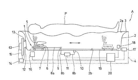
Figs. 1 and 2 are schematic views illustrating a usage
status of the water bed type massaging machine according to an
embodiment of the present invention. A water bed type massaging
machine A according to the embodiment of the present invention
is constructed with a water bed having a rectangular box-shaped
water container 2 with an opening portion 2a on top thereof in
which water or warm water is filled, and a flexible sheet 3
CA 0224~819 1998-08-10
mounted extending over the opening portion 2a in a water-tight
manner. On the bottom surface 2b of the water container 2 is
mounted a jet device 1 so as to be movable in a reciprocal way
toward the heightwise direction and the breadthwise direction of
the shoulders of a person P being massaged while lying on the
flexible sheet 3.
A detailed description will now be made of the construction
of each portion of the water bed type massaging machine A.
As shown in Figs. 1 and 2, the water container 2 is formed
with a water inlet 10 in the bottom surface 2b thereof and a
water outlet 9 in a side wall 2c thereof. Between the water
inlet 10 and the water outlet g is interposed a circulating pump
11 in a relationship spaced therefrom. With the water outlet 9
are communicated nozzles 5 and 5 disposed in the jet device 1 so
as to be associated therewith. In the drawings, reference symbol
8a stands for a flexible water discharge hose capable of
following the reciprocal movement of the jet device 1 and
branched off into two sections which in turn are connected to
the nozzles 5 and 5 and reference symbol ab stands for a
connecting pipe.
Driving the circulating pump 11 allows a suction of warm
water or the like in the water container 2 through the water
inlet 10 and a jetting of warm water or the like from the
nozzles 5 and 5.
As shown in Fig. 2, the water container 2 is also provided
with a drive pulley 24 and a follower pulley 23 at the both
lengthwise ends of the bottom surface 2b and a belt 25 for
transferring the jet device is wound between the follower pulley
23 and the drive pulley 24. A rail 19 is disposed beneath and in
parallel to the belt 25 for transferring the jet device and a
spline shaft 22 for transferring the nozzles 5 and 5 in the
breadthwise direction of the shoulders of the person on the side
of and along the belt 25 for transferring the jet device.
CA 0224~819 1998-08-10
Then, a description will be made of the construction of the
jet device 1 by breaking it down into the construction for
transferring the nozzles 5 and 5 in the heightwise direction of
the person P being massaged and the construction for
transferring them in the breadthwise direction of the shoulders
of the person.
First, a description will be made of the construction of
the jet device 1 for transferring the nozzles 5 and 5 in the
heightwise direction of the person P being massaged.
As shown in Figs. 3 and 4, the jet device 1 has a pair of
gears 6 and 6 for transferring the nozzles disposed on an upper
side of a carrier 7 and rolling wheels 30 and 30 on a bottom
side of the carrier 7.
The carrier 7 has support members 7d and 7d for supporting
the rolling wheels mounted suspending down from a bottom side
surface of a base table 7b in the form of a flat plate and the
rolling wheels 30 and 30 are supported axially with the support
members 7d and 7d for supporting the rolling wheels. In the
drawings, reference numeral 31 stands for a rotary shaft.
The carrier 7 is also provided with belt support members 7a
and 7a upstanding on the upper side surface of the base table 7b
and the belt 25 for transferring the jet device is clamped with
the belt support members 7a and 7a. In the drawing, reference
numerals 34 and 35 stand for a fixing bolt and a fixing nut,
respectively.
Now, a description will be made of a mechanism for
rotatably transferring the belt 25 for transferring the jet
device with reference to Fig. 5. The belt 25 for transferring
the jet device is associated with and connected to a motor 16
for driving the belt disposed at the bottom side of the water
container 2 through the drive pulley 24. More specifically, a
pulley shaft 47 is associated with and connected to the motor 16
for driving the belt and the drive pulley 24 is mounted on the
CA 0224~819 1998-08-10
top of the pulley shaft 47 with which in turn is installed the
belt 25 for transferring the jet device. The pulley shaft 47 is
supported with a cylinder 50 for supporting the pulley shaft
mounted through a throughhole 2e formed in the bottom surface 2b
of the water container 2 so as to be rotatable. In the drawing,
reference numeral 4 a stands for a drive bevel gear mounted on an
output shaft 56 of the belt-driving motor 16, reference numeral
49 for a follower bevel gear engageable with the drive bevel
gear 48, reference numeral 51 for a packing member, reference
numeral 52 for a bearing, reference numeral 53 for a mounting
nut, and reference numeral 64 for an oil seal.
The belt 25 for transferring the jet device is rotated by
driving the belt-driving motor 16 to allow a reciprocal movement
of the jet device 1 connected to the belt 25 in the lengthwise
direction of the water container 2 along the rail 19, in other
words, in the heightwise direction of the person P being
massaged while lying on the flexible sheet 3.
At a bottom edge portion of the pulley shaft 47 is disposed
a rotary encoder 54 to specify the position of the jet device 1
by measuring an amount of rotation of the pulley shaft 47. In
the drawing, reference numeral 55 stands for a detecting disk
mounted on the bottom edge portion of the pulley shaft 47.
Then, a description will be made of the construction of the
jet device 1 for transferring the nozzles 5 and 5 in the
breadthwise direction of the shoulders of the person P being
massaged.
As shown in Figs. 3 and 4, the jet device 1 is axially
supported on an upper side of the carrier 7 in a state that a
pair of the gears 6 and 6 for transferring the nozzles are
engaged with each other. More specifically, shaft support
cylinders 36 and 36 are disposed upstanding on the upper surface
of the base table 7b of the carrier 7 and rotating shafts 29 and
29 of the respective gears 6 and 6 for transferring the nozzles
are inserted into hollow portions of the shaft support cylinders
CA 0224~819 1998-08-10
36 and 36. On the upper surface of the gears 6 and 6 for
transferring the nozzles are mounted the nozzles 5 and 5 so as
to be rotatable axially about the rotary shaft 5b. In the
drawing, reference symbol 5a stands for a blow-off outlet of the
nozzle 5.
A description will now be made of a mechanism for rotating
the gears 6 and 6 for transferring the nozzles with reference to
Figs. 4 and 6. The gears 6 and 6 for transferring the nozzles
are associated with and connected to the spline shaft 22 which
in turn is spline-engaged with a driving bevel gear 40 to allow
an association with and a connection to the gears 6 and 6 for
transferring the nozzles. The driving bevel gear 40 is supported
axially with a gear holder 21 disposed next to a side portion of
the carrier 7. In the drawing, reference numeral 32 stands for
an intermediate gear engageable with the gear 6 for transferring
the nozzle, reference numeral 41 for a follower bevel gear
integrally formed with the intermediate gear 32, reference
numeral 44 for a driving gear mounted on an output shaft 57 of
the motor 17 for transferring the nozzles, reference numeral 43
for a follower gear engageable with the driving gear 44, and
reference numeral 45 for a key for spline-engagement of the
driving bevel gear 40 with the spline shaft 22.
By driving the motor 17 for transferring the nozzles in the
construction as described hereinabove, the spline shaft 22 is
rotated and the driving bevel gear 40 is also rotated. Further,
a pair of the gears 6 and 6 for transferring the nozzles are
allowed to rotate in the directions opposite to each other to
transfer a pair of the nozzles 5 and 5 in the directions in
which they come closer to each other or they become separated
from each other, more specifically, to transfer the nozzles 5
and 5 in the breadthwise direction of the shoulders of the
person P being massaged while lying on the flexible sheet 3 and
symmetrically in the left and right directions.
In Fig. 6, reference numeral 46 stands for a potentiometer
mounted on a one end of the spline shaft 22 to allow the
CA 0224~819 1998-08-10
determination of the positions of the nozzles 5 and 5 by
measuring the amount of rotation of the spline shaft 22.
As described hereinabove, the water bed type massaging
machine A can offer higher massaging effects by stimulating
various locations of the person P being massaged on the areas
symmetrically on the left- and right-hand sides in the
breadthwise direction of the shoulders with respect to the
backbone of the person P being massaged, because the nozzles 5
and 5 are disposed so as to be transferred in a reciprocal
manner in the heightwise direction and in the breadthwise
direction of the shoulders as well as symmetrically in the left
and right directions of the person P being massaged while lying
on the flexible sheet 3.
Further, in this embodiment, two pieces of the gears 6 and
6 for transferring the nozzles are used which are equal in size
to each other so that the jet device 1 can be constructed in a
simple arrangement. Moreover, as the gears 6 and 6 for
transferring the nozzles can be made equal in size to each
other, the jet device 1 can also be made simple in construction
and eventually the water bed type massaging machine A can be
assembled in a ready manner and made superior in maintenance.
Then, a description will be made of the construction of
mounting the flexible sheet 3.
As shown in Fig. 7, the flexible sheet 3 is disposed to
cover the peripheral edge of the opening portion 2a of the water
container 2. More specifically, the opening portion 2a of the
water container 2 is formed at its peripheral edge with a flange
58 which is provided with a peripheral groove 59 in which the
edge portion of the flexible sheet 3 is once folded and inserted
and with which a sealing frame 60 is engaged. The sealing frame
60 is then pressed with a lock plate 62 to allow the fixing of
the edge portion of the flexible sheet 3 in the peripheral
groove 59. The lock plate 62 is fixed through the flange 58 to a
frame 4 with a bolt 61.
CA 0224~819 1998-08-10
With the arrangement as described hereinabove, the water
container 2 can hold water and so on therein in a water-tight
manner and prevent the water and so on from leaking outside the
water container 2.
The flexible sheet 3 is made of a flexible rubber material
which is thin and has elasticity so as to comfortably adapt the
shape of the body of a person ~eing massaged and it can support
the body of the person being massaged in association with the
water or the like in the water container 2.
The arrangement of the flexible sheet 3 can provide a
comfortable feeling of resting thereon upon lying on the
flexible sheet 3 and transmit the pressure of the jet streams
from the ~et device 1 to the person e being massaged, thereby
realizing a comfortable massaging.
Now, a description will be made of the construction of
maintaining the temperature of the hot water or the like in the
water container 2 at an optimal level.
As shown in Figs. 1 and 2, a side wall 2d of the water
container 2 is provided with a suction opening 12 and a
discharge opening 13, and a suction pump 14 and a radiator 15
are interposed between the suction opening 12 and the discharge
opening 13. On the radiator 15 is mounted a cooling fan 63. The
side wall 2c of the water container 2 is provided with a heater
18. In the drawing, reference numeral 33 stands for a connecting
pipe.
Hot water or the like in the water container 2 can be
allowed to cool by sucking the hot water or the like from the
suction opening 12 with the suction pipe 14, forcibly cooling it
with the radiator 15 and the cooling fan 63, and then supplying
the cooled water or the like again into the water container 2
from the discharge opening 13. The hot water or the like in the
water container 2 can also be warmed with the heater 18.
In this arrangement, a water temperature sensor is disposed
CA 0224~8l9 l998-08-lO
14
in the water container 2 to measure the temperature of the hot
water or the like in the water container 2, thereby enabling the
temperature of the water or the like in the water container 2 to
be maintained always at an optimal level by heating or cooling
the water or the like and leading to an increase in massaging
effects. As the water or the like in the water container 2 can
be sustained at the optimal temperature in the manner as
described hereinabove, the person P being massaged while lying
on the flexible sheet 3 can enjoy a pleasant feeling because the
flexible sheet 3 can be maintained at a temperature that can be
perceived by the person P being massaged as being not too hot or
too cold.
Further, as the water bed type massaging machine A is
arranged such that the hot water or the like in the water
container 2 can be cooled even if the temperature of the water
or the like therein would be elevated due to a friction of the
hot water or the like in the water container 2 caused by the jet
streams blown thereinto from the jet device 1, the water bed
type massaging machine A can be operated continuously for a long
period of time.
In this embodiment, although the hot water or the like in
the water container 2 can be cooled with the radiator 15 and the
cooling fan 63, it is also possible to cool the hot water or the
like in the water container 2 with a pipe mounted in the inside
of the water container 2 by passing cooling water through the
pipe.
In the water bed type massaging machine A with the above
arrangement, as shown in Figs. 1 and 2, the water bed type
massaging machine A is installed with a controller 20 for
controlling the operations of the circulating pump 11, the motor
16 for driving a belt, the motor 17 for transferring the
nozzles, the suction pump 14 and the heater 18 as well as with
an operation panel 26 for operating the controller 20.
In the arrangement as described hereinabove, a variety of
CA 0224~819 1998-08-10
controls can be implemented, which may include controls over the
pressure of the water to be blown from the nozzles 5 and 5, the
positions of the nozzles 5 and 5, and the temperature of the
water in the water container 2, among others. In particular, as
the water bed type massaging machine A in the above arrangement
can provide the person P being massaged with continuously
varying stimuli by varying the magnitude of the jet streams
blown from the nozzles 5 and 5 periodically or in a random
fashion, the water bed type massaging machine A can offer higher
massaging effects without allowing the person P being massaged
to get used to an action produced by monotonous stimuli.
Therefore, the water bed type massaging machine A can
provide a various manner of massaging appropriately in
accordance with situations and preferences of the person P being
massaged (referring to Figs. 21 to 27~.
Fig. 21 shows loci S of the massaging locations obtained
when the nozzles 5 and 5 are transferred in a reciprocal manner
in the heightwise direction of the person P being massaged. In
this case, only the carrier 7 is transferred reciprocally in the
heightwise direction of the person P being massaged. As shown in
Fig. 21, this way of massaging enables jet streams blown from
the nozzles 5 and 5 to provide stimuli onto effective spots for
effectively producing stimuli, which are present over a wide
area extending continually from the head to the feet of the
person P being massaged.
Fig. 22 indicates loci S of massaging locations when the
nozzles 5 and 5 are transferred in a reciprocal way in the
breadthwise direction of the shoulders of the person P being
massaged. In this case, the carrier 7 is transferred in an
appropriate way in the heightwise direction of the person P
being massaged to transfer the nozzles 5 and 5 reciprocally in a
straight way in the heightwise direction of the person P being
massaged, the nozzles 5 and 5 being transferred in an arc-shaped
manner by the rotation of the gears 6 and 6 for transferring the
nozzles. Then, as shown in Fig. 22, jet streams blown from the
CA 0224~8l9 l998-08-lO
16
nozzles 5 and 5 stimulate a variety of effective spots of the
person P being massaged for effectively producing stimuli, which
are present continually on the left-hand and right-hand sides
with the backbone of the person P being massaged centered
therebetween.
Fig. 23 illustrates loci S of massaging locations when the
nozzles 5 and 5 are rotated. In this case, only the gears 6 and
6 for transferring the nozzles are rotated at given locations of
the person P being massaged. Further, as shown in Fig. 23, jet
streams blown from the nozzles 5 and 5 are designed so as to
provide stimulation around effective spots for effectively
producing comfortable stimuli as if massaging by hands, the
effective spots being present on the back of the person P being
massaged.
Fig. 24 shows loci S of the massaging locations when the
nozzles 5 and 5 are transferred in the heightwise direction of
the person P being massaged while rotating the nozzles 5 and 5.
In this case, the carrier 7 is transferred in the heightwise
direction of the person P being massaged while rotating the
gears 6 and 6 for transferring the nozzles. As shown in Fig. 24,
jet streams blown from the nozzles 5 and 5 are designed so as to
stimulate as a whole effective spots for effectively producing
comfortable stimuli, the effective spots being present on the
back of the person P being massaged.
Fig. 25 indicates loci S of massaging locations when the
nozzles 5 and 5 are transferred in the heightwise direction of
the person P being massaged while transferring the nozzles 5 and
5 reciprocally in the breadthwise direction of the shoulders of
the person. In this case, the carrier 7 is transferred in an
appropriate way in the heightwise direction of the person P
being massaged in order to transfer the nozzles 5 and 5 in the
heightwise direction of the person P being massaged, too, while
reciprocally transferring them in a linearly straight manner in
the breadthwise direction of the shoulders of the person, the
nozzles 5 and 5 being in an arc-shaped way by the rotation of
CA 0224~819 1998-08-10
the gears 6 and 6 for transferring the nozzles. Further, in this
case, as shown in Fig. 25, a variety of effective spots for
effectively providing comfortable stimuli can be stimulated as a
whole by jet streams blown from the nozzles 5 and 5, the
effective spots being present continually on the both light-hand
and right-hand sides of the person P being massaged with respect
to the backbone of the person P being massaged.
Fig. 26 illustrates loci S of massaging locations when jet
streams are blown intermittently from the nozzles 5 and 5 while
transferring the nozzles 5 and 5 in the heightwise direction of
the person P being massaged. In this case, the circulating pump
11 is operated intermittently while only the carrier 7 is being
transferred in the heightwise direction of the person P being
massaged. As shown in Fig. 26, in this case, the jet streams
blown from the nozzles 5 and 5 can stimulate a variety of
effective spots for effectively producing comfortable stimuli in
a direct and concentrated way, the effective spots being present
in the area extending from the head portion to the feet portion
of the person P being massaged.
On the other hand, the person P being massaged may become
getting used to stimuli when the stimuli are monotonous and such
monotonous stimuli are provided continuously to the person P
being massaged. Like in this case, however, when stimuli are
provided intermittently to the person P being massaged, the
person can be prevented from having getting used to such
stimuli. Moreover, when a magnitude of blowing jet streams or an
interval of blowing jet streams from the nozzles 5 and 5 is
varied in a random manner, continuously varying stimuli are
given the person P being massaged. This can enhance massaging
effects to a higher level without causing the person P being
massaged to become getting used to such stimuli.
Fig. 27 shows loci S of massaging locations when the
nozzles 5 and 5 are transferred in the breadthwise direction of
the shoulders of the person P being massaged, too, while
transferring them reciprocally in the heightwise direction of
CA 0224~8l9 l998-08-lO
18
the person. This case of massaging is carried out by rotating
the gears 6 and 6 for transferring the nozzles after the carrier
7 has been transferred in the heightwise direction of the person
P being massaged, and then transferring the carrier 7 in the
heightwise direction of the person being massaged. As shown in
Fig. 27, in this case, jet streams blown from the nozzles 5 and
5 can stimulate a variety of effective spots for effectively
producing comfortable stimuli present over the back of the
person P being massaged as a whole.
The water bed type massaging machine A can stimulate a
variety of effective spots for effectively producing comfortable
and pleasant stimuli present over the back of the person P being
massaged by jet streams blown from the nozzles 5 and 5 in the
manner as described hereinabove. Likewise, it can provide
comfortable and pleasant stimuli to the light-hand and right-
hand sides of the person P being massaged symmetrically with
respect to the backbone of the person P being massaged. Thus, it
can produce higher massaging effects.
Now, a description will be made of another embodiment of
the jet device 1.
Figs. 8 and 9 illustrate a jet device according to a second
embodiment of the present invention. In the second embodiment,
the jet device 1 has a nozzle transferring shaft 71 disposed on
top of the carrier 7 so as to be rotatable, a right-hand screw
thread 71a formed on an outer peripheral right-hand side surface
of the nozzle transferring shaft 71, and a left-hand screw
thread 71b formed on an outer peripheral left-hand side surface
thereof, and the right-hand and left-hand screw threads 71a and
71b thread nozzle transferring members 74 and 74 fixed to the
nozzles 5 and 5, respectively. In the drawings, reference
numeral 72 stands for a shaft support member with the nozzle
transferring shaft 71 inserted therethrough rotatably and
reference numeral 73 for a mounting vis.
A one edge portion of the nozzle transferring shaft 71 is
CA 0224~819 1998-08-10
19
connected to a flexible shaft 70 so as to be associated
therewith. The flexible shaft 70 is coupled with and associated
with the motor 17 for transferring the nozzles disposed on the
back side of the side wall 2d of the water container 2 so as to
transmit the power of the motor 17 for transferring the nozzles
to the jet device 1 within the water container 2.
In the arrangement of the construction as described
hereinabove, the nozzle transferring shaft 71 is rotated via the
flexible shaft 70 by driving the motor 17 for transferring the
nozzles, thereby transferring a pair of the nozzles 5 and 5 in
the directions in which they come closer to each other or they
are separated apart from each other, in other words, in the
breadthwise direction of the shoulders of the person P being
massaged while lying on the flexible sheet 3.
Fig. 10 shows a jet device according to a third embodiment
of the present invention. In this embodiment, the jet device 1
has a nozzle transferring shaft 71 disposed on top of the
carrier 7 so as to be rotatable and a right-hand screw thread
71a formed on an outer peripheral side surface of the nozzle
transferring shaft 71, and a moving member 76 is screwed with
the right-hand screw thread 71a. The moving member 76 and a
shaft support member 72 fixed to an edge portion of the carrier
7 are connected to a pair of light-hand and right-hand
connecting members 77 and 77 via a nozzle transferring member 74
with each of the nozzles 5 and 5 fixed thereto. A one edge
portion of the nozzle transferring shaft 71 is coupled with and
associated with a flexible shaft 70 having a construction
similar to the flexible shaft 70 in the second embodiment as
described hereinabove. In the drawing, reference numeral 72
stands for a shaft support member with the nozzle transferring
shaft 71 inserted rotatably therethrough, reference numeral 73
for a mounting vis, and reference numeral 75 for a connecting
pin.
In the above arrangement, driving the motor 17 for
transferri~g the nozzles rotates the nozzle transferring shaft
CA 0224~819 1998-08-10
71 via the flexible shaft 70 and transfers the moving member 76
along the nozzle transferring shaft 71, thereby transferring a
pair of the nozzle transferring members 74 and 74 and the
nozzles 5 and 5 via the connecting members 77 and 77,
respectively, in the directions in which they come closer to
each other or they are separated apart from each other, that is,
in the breadthwise direction of the shoulders of the person P
being massaged while lying on the flexible sheet 3.
Fig. 11 indicates a jet device according to a fourth
embodiment of the present invention. In this embodiment, the jet
device 1 has a shaft support member 7e disposed upstanding on
top of the carrier 7 and a flexible shaft 70 inserted through
the shaft support member 74, which has a construction similar to
the flexible shaft 70 as in the second embodiment as described
hereinabove. To a topside end of the flexible shaft 70 is
connected a pinion gear ao so as to be associated therewith. A
pair of rack gears 78 and 78 are coupled with the pinion gear 80
mounted on top of the carrier 7 so as to be associated with the
pinion gear 80, and the rack gears 78 and 78 are provided with
the respective nozzles 5 and 5. In the drawing, reference
numeral 7g stands for a secondary support member disposed so as
to make a pair of the nozzles 5 and 5 equal to each other in
height.
In this arrangement, the pinion gear 80 is rotated via the
flexible shaft 70 by driving the motor 17 for transferring the
nozzles, thereby transferring the rack gears 78 to the left and
the right, respectively, so that a pair of the nozzles 5 and 5
are transferred in the directions in which they come closer
together or they are separated apart from each other, that is,
in the breadthwise direction of the shoulders of the person P
being massaged while lying on the flexible sheet 3.
Figs. 12 and 13 illustrate a jet device according to a
fifth embodiment of the present invention. In this embodiment,
the jet device 1 has a follower pulley 81 for transferring a
nozzle supported axially on top of the carrier 7 and a pinion
CA 0224~819 1998-08-10
gear 89 connected coaxially thereto and associated therewith on
top of the nozzle-transferring follower pulley 81. To the pinion
gear 89 are connected nozzle transferring members 83 and 83 with
the nozzles 5 and 5 mounted thereon each at a topside edge
thereof so as to be associated therewith. More specifically, the
pinion gear 89 is screwed with a rack gear 82a to a topside edge
of which is connected a connecting member 82. The connecting
member 82 is formed with guide holes 82b and 82b directed
horizontally and connected slidably to the respective base ends
of the nozzle transferring members 83 and 83. The nozzle
transferring members 83 and 83 are disposed crossing each other
in their middle positions and connected at their topside ends to
the nozzles 5 and 5, respectively. In the drawings, reference
numeral 86 stands for a shaft and reference numeral 87 for a
connectlng pln.
Fig. 13 shows a mechanism for rotating the nozzle-
transferring follower pulley 81. The water container 2 is
disposed at a right-hand edge portion thereof with a drive
pulley 90 for transferring the nozzle, which in turn is
connected to the nozzle-transferring follower pulley 81 with a
connecting member 85 connected rotatably through a pin 92. On
the pin 92 is further mounted a tension pulley 91 so as to be
rotatable, and an endless timing belt 84 is wound on the tension
pulley 91, the nozzle-transferring drive pulley 90 and the
nozzle-transferring follower pulley 81. The nozzle-transferring
drive pulley 90 is coupled with the motor 17 for transferring
the nozzles at a lower portion of the water container 2 so as to
be associated with each other, although not shown, thereby
allowing the power of the motor 17 for transferring the nozzles
to be transmitted to the jet device 1 within the water container
2.
In the arrangement of the construction as described
hereinabove, driving the motor 17 for transferring the nozzles
rotates the nozzle-transferring follower pulley 81 through the
timing belt 84 to transfer a pair of the nozzles 5 and 5 in the
CA 0224~819 1998-08-10
22
directions in which they come closer to each other or they are
separated apart from each other, that is, in the breadthwise
direction of the shoulders of the person P being massaged while
lying on the flexible sheet 3.
Figs. 14 and 15 illustrate a jet device according to a
sixth embodiment of the present invention. In this embodiment,
the jet device 1 has shaft support members 7e and 7e disposed
upstanding on top of the carrier 7 and a pair of gears 93 and 93
for transferring nozzles supported axially each in an engaged
state to the shaft support members 7e and 7e, each of the gears
93 and 93 being fixed with the nozzles 5 and 5, respectively. On
top of the carrier 7 is disposed a follower pulley 81 for
transferring the nozzle so as to be rotatable, and the nozzle-
transferring follower pulley 81 is connected coaxially to a gear
94 for transferring a nozzle, which in turn is toothed with the
respective nozzle-transferring gear 93. In the drawings,
reference numeral 88 stands for a rotary shaft.
Fig. 15 illustrates a mechanism for rotating the nozzle-
transferring follower pulley 81. The water container 2 iS
disposed at a right-hand edge portion thereof with the nozzle-
transferring drive pulley 90 and at a left-hand edge portion
thereof with a follower pulley 97, and an endless timing belt 84
is wound about the pulleys 90 and 97. The timing belt 84 is
coupled with and associated with the nozzle-transferring
follower pulley 81, and the nozzle-transferring drive pulley 90
is coupled with and associated with the motor 17 for
transferring the nozzles disposed at the lower portion of the
water container 2. This arrangement allows the power of the
motor 17 for transferring the nozzles to be transmitted to the
jet device 1 within the water container 2. In the drawing,
reference numeral 96 stands for a tension pulley.
In this arrangement as described hereinabove, the nozzle-
transferring follower pulley 81 is rotated via the timing belt
84 by driving the motor 17 for transferring the nozzles to
transfer a pair of the nozzles 5 and 5 in the directions in
CA 0224~819 1998-08-10
which they come closer to each other or they part from each
other, that is, in the breadthwise direction of the shoulders of
the person P being massaged while lying on the flexible sheet 3.
Figs. 16 to 18, inclusive, illustrate a jet device
according to a seventh embodiment of the present invention. In
this embodiment, the jet device comprises an upper-half jet
device lU for the upper half of the body of a person being
massaged and a lower-half jet device lD for the lower half of
the body thereof. As shown in Fig. 17, a water container 2 is
provided with drive pulleys 24U and 24D and follower pulleys 23U
and 23D on the respective lengthwise ends of the bottom surface
2b, and a belt 25U for transferring the jet device is wound
about the pulleys 23U and 24U while a belt 25D for transferring
the jet device is wound about the pulleys 23D and 24D. Beneath
the belts 25U and 25D for transferring the respective the jet
devices is disposed a rail 19 common for the upper-half and the
lower-half of the body of the person being massaged along and in
parallel to the belts 25U and 25D for transferring the jet
devices. A spline shaft 22U is disposed along the side of the
belt 25U for transferring the ~et device and a spline shaft 22D
is disposed along the side of the belt 25D for transferring the
jet device. In the drawings, reference symbols 9U and 9D stand
for blow-off outlets, reference symbols 10U and 10D for water
inlets, reference symbols llU and llD for circulating pumps,
reference 17U and 17D for motors for transferring the nozzles,
and reference symbols 19a, 19b and l9c each for a rail groove.
The upper-half jet device lU has a construction
substantially the same as the construction of the jet device
according to the first embodiment above, as shown in Fig. 18. In
the upper-half jet device lU, a carrier 7U is connected to and
associated with the jet device-transferring belt 25U. On the
other hand, the lower-half iet device lD has the construction
symmetrical sideways to the construction of the upper-half jet
device lU, in which a carrier 7D is connected to and associated
with the belt 25D for transferring the jet device.
CA 0224~819 1998-08-10
24
In this embodiment, the jet device-transferring belts 25U
and 25D are rotated by driving the motors 16U and 16D for
driving the belts, respectively, to reciprocally transfer the
jet devices lU and lD connected to the belts 25U and 25D,
respectively, in an independent manner in the lengthwise
direction within the water container 2 along the rail 19, that
is, reciprocally in the heightwise direction of the person P
being massaged while lying on the flexible sheet 3.
Therefore, the water bed type massaging machine A can carry
out various modes of massaging each of the upper half and the
lower half of the body of the person P being massaged in an
appropriate manner (referring to Figs. 28 and 29).
Fig. 28 shows loci S of massaging locations when the
nozzles 5 and 5 are transferred reciprocally in the breadthwise
direction of the shoulders of the person P being massaged for
the upper half of the body thereof and when they are transferred
reciprocally in the heightwise direction of the person for the
lower half of the body thereof.
Fig. 29 indicates loci S of massaging locations when the
nozzles 5 and 5 are transferred in the heightwise direction of
the person being massaged while rotating them for the upper half
of the body of the person being massaged and when the nozzles 5
and 5 are transferred reciprocally in the breadthwise direction
of the shoulders of the person being massaged for the lower half
of the body thereof.
An appropriate combination of various modes of massaging as
shown in Figs. 21 to 27 above can carry out various modes of
massaging simultaneously in accordance with the locations of the
person P being massaged.
Figs. 19 and 20 illustrate a jet device according to an
eighth embodiment of the present invention. In this embodiment,
the jet device comprises a left-side jet device lL for the left-
hand side of a person being massaged and a right-side jet device
CA 0224~819 1998-08-10
lR for the right-hand side thereof. As shown in Fig. 19, a water
container 2 is provided with drive pulleys 24L and 24R and
follower pulleys 23L and 23R on the lengthwise ends of the
bottom surface 2b, and a belt 25L for transferring the jet
device is wound about the pulleys 23L and 24L while a belt 25R
for transferring the iet device is wound about the pulleys 23R
and 24R. Beneath the belts 25L and 25R for transferring the
respective the jet devices are disposed rails l9L and 19R along
and in parallel to the belts 25L and 25R for transferring the
jet devices, respectively. A spline shaft 22L is disposed along
the side of the belt 25L for transferring the jet device and a
spline shaft 22R is disposed along the side of the belt 25R for
transferring the jet device. In the drawings, reference symbols
9L and 9R stand for blow-off outlets, reference symbols 10L and
10R for water inlets, reference symbols llL and llR for
circulating pumps, and reference 17L and 17R for motors for
transferring the nozzles.
As shown in Fig. 20, the left-side jet device lL supports
axially the nozzle-transferring gear 5 on the upper portion of a
carrier 7L and the nozzle 5 is mounted on the upper surface of
the nozzle-transferring gear 6 so as to be rotatable about the
rotary shaft 5b. In the left-side jet device lL, the carrier 7L
is connected to and associated with the jet device-transferring
belt 25L. On the other hand, the right-side jet device lR has
the construction symmetrical sideways to the construction of the
left-side jet device lL, in which a carrier 7R is connected to
and associated with the belt 25R for transferring the jet
device.
In this embodiment, the jet device-transferring belts 25L
and 25R are rotated by driving the motors 16L and 16R for
driving the belts, respectively, to reciprocally transfer the
jet devices lL and lR connected to the belts 25L and 25R,
respectively, in an independent manner in the lengthwise
direction of the water container 2 along the rails 19L and l9R,
that is, reciprocally in the heightwise direction of the person
CA 0224~819 1998-08-10
26
P being massaged while lying on the flexible sheet 3
independently for the left-half and right-half sides of the
person's body being massaged.
Therefore, the water bed type massaging machine A can carry
out various modes of massaging each of the upper half and the
lower half of the body of the person P being massaged in an
appropriate manner (referring to Fig. 30).
Fig. 30 shows loci S of massaging locations when the
nozzles 5 and 5 are transferred in the heightwise direction of
the person P being massaged while rotating them for the left-
half side of the person's body being massaged and when the
nozzles 5 and 5 are transferred reciprocally in the breadthwise
direction of the shoulders of the person P being massaged for
the right-half side of the person's body being massaged.
The water bed type massaging machine according to the
present invention can implement various modes of massaging
simultaneously in accordance with the locations of the person P
being massaged by combining various modes of massaging as shown
in Figs. 21 to 27, inclusive, in an appropriate manner.
INDUSTRIAL UTILIZABILITY
The present invention can be practiced in the manner as
described hereinabove and demonstrate the effects as will be
described hereinafter.
More specifically, the water bed is constructed with a box-
shaped water container with an opening portion disposed on top
thereof, in which water or warm water is filled, and with a
flexible sheet disposed covering the opening portion in a water-
tight manner, so as to allow a person being massaged to lie on
the upper surface of the flexible sheet. Also, the interior of
the water container is provided with light-hand and right-hand
nozzles capable of blowing water or warm water against the back
surface of the flexible sheet and the light-hand and right-hand
nozzles are disposed so as to be transferred each in the
CA 0224~819 1998-08-10
heightwise direction and in the breadthwise direction of the
shoulders of the person being massaged, including being
transferred in a rotatable way. Therefore, the person being
massaged can be massaged over the entire body thereof by
providing stimuli thereto by jet streams to the person being
massaged in a state in which the person is lying on the flexible
sheet, thereby assisting the person being massaged in recovering
or relieving from fatigue and alleviating localized stiff muscle
of the person being massaged.
Also, the water bed is constructed with a box-shaped water
container with an opening portion disposed on top thereof, in
which water or warm water is filled, and with a flexible sheet
disposed covering the opening portion in a water-tight manner,
so as to allow a person being massaged to lie on the upper
surface of the flexible sheet, wherein the water container is
provided within the interior thereof with a pair of light-hand
and right-hand nozzles so as to blow water or warm water toward
the back surface of the flexible sheet and the pair of the
light-hand and right-hand nozzles are further disposed so as to
move in the heightwise direction of the person being massaged as
well as to move in the breadthwise direction of the shoulders of
the person symmetrically in the left- and right-hand directions.
Therefore, the water bed is arranged to transfer the pair of the
nozzles in the heightwise direction and in the breadthwise
direction of the shoulders of the person being massaged,
including rotating the nozzles, thereby providing comfortable
and pleasant stimuli onto various locations symmetrically
sideways in the breadthwise direction of the shoulders with
respect to the backbone of the person being massaged centered
therebetween and consequently achieving higher massaging
effects.
Further, the water container is disposed in the interior
thereof with the carrier so as to be movable in the heightwise
direction of the person being massaged and a pair of the gears
for transferring the nozzles are rotatably disposed on top of
CA 0224~819 1998-08-10
2~
the carrier in a state in which they are engaged while the
nozzles are provided on the pair of the gears for transferring
the nozzles. Therefore, the pair of the nozzles can be
transferred, including rotating, and the jet device can be
formed into a simple structure, thereby providing the water bed
type massaging machine which can be assembled in a ready manner
and has a high degree of maintenance performance.
Furthermore, as the water bed type massaging machine is
provided with the temperature adjustment means for adjusting the
temperature of water or warm water filled in the interior of the
water container, the water or the like in the water container
can be heated or cooled to maintain the temperature of the water
or the like in the water container always at an optimal level.
In addition, the water bed type massaging machine according to
the present invention can sustain the flexible sheet at an
optimal temperature so that massaging effects can be enhanced
and the person being massaged while lying on the flexible sheet
can enjoy the massaging without undergoing an unpleasant feeling
because the flexible sheet does not become too hot or too cold.
Moreover, the water bed type massaging machine can be
operated continuously for a long period of time because the hot
water or the like in the water container can be cooled down even
if the temperature of the water or the like in the water
container would become higher due to friction of the water or
the like.