Note: Descriptions are shown in the official language in which they were submitted.
CA 02245864 2004-09-O1
CUTTING DIE AND METHOD OF FORMING
Background of the Invention
This invention relates to cutting dies and, in particular, to the
manufacture of dies for cutting various stock materials.
Cutting dies are known for cutting or severing one portion of a
stock material from another. For example, cutting dies are used for cutting
sheets of paperboard or plastic or metal into predetermined blanks. In one
form
of known cutting operation, two rotary cylinders, each having small integral
cutting blades extending radially from the cylindrical surface, are juxtaposed
so
that when rotated, the blades engage generally opposite sides of a work stock
and cooperate to sever the stock into a blank, the shape of which is
determined
by the blade configuration. One such operation is illustrated in U.S. Patent
No.
4,608,905.
The process of forming each cylindrical die requires certain
process treatments to insure the blades will provide the desired cutting
CA 02245864 1998-08-11
WO 97!29879 PCT/US97l02482
-2-
action over a tong operational life. Specifically, the blades must be very
hard in order to provide sufficient blade life before reconditioning is
required.
In one form of die preparation then, an entire die cylinder of
appropriate size is heat-treated to bring the cylinder's surface to a
requisite hardness, on the order, for example of about HRC 60 on the
Rockwell hardness scale. Since the blades are formed integrally from the
cylinder, the next process is to remove cylinder material to form and
define the integral blades which are to extend radially outwardly from the
cylinder's surface. While it might be possible to mill the surface down
to form the blades, the hardness of the cylinder makes milling a bad
choice.
Accordingly, it is known to use the process of electro
discharge machining (EDM) to form the die. In this process, a graphite
cylinder is formed in the negative configuration of the to-be-formed die
cylinder and blades. The graphite cylinder and die cylinder are
juxtaposed in an electric discharging environment so the die cylinder
metal is eaten away, leaving the hardened cutting blades extending
upwardly from the relieved cylinder surface. This is a slow process and,
where the cylinder is large, such as twelve inches or even more in
diameter and several feet long, the process can take days. '
CA 02245864 2004-09-O1
-3-
Manufacturers have attempted to form the die first, then harden
it. This reversed procedure does not work well. The cylinder and its extended
blades must be heated to austentiting temperature, which is about
1038°C
(1900°F) to 1093°C (2000°F) for D2 steel, in order to
produce the desired blade
hardness. When such a pre-formed cylinder is removed from the furnace to
cool down, it may distort or crack in the areas around or in the die blades.
This
distortion is believed to be due to several principles, including thermal
deformation and phase transformation deformation resulting from differential
cooling rates between the relative low mass blades and the high mass cylinder,
and between surface and interior of a die.
More particularly, when the cylinder cools, its surface cools faster
than the interior. Uneven volume change due to both thermal and phase
transformation causes the die to crack or distort beyond acceptable limits.
Also,
in order to produce the hardening required, the metal must be heated to the
necessary level to cause the desired phase transformation. While such phase
transformation in the blades is desired in order to produce the desired
hardness, the fast cooling required from austentiting temperature of about
1038°C (1900 ° F) to produce the phase transformation is a cause
of undesirable
cracking and distortion of the blades on the cylinder due to the varied rates
of
phase transformation between die surface and interior. These phase
transformations in the
CA 02245864 1998-08-11
WO 97!29879 . PCTlUS97/02482
-4-
metal take place at different rates due to the heat distribution throughout
the varied mass configuration of the blades and the cylinder. This
produces volumetric or density changes which can cause cracking or
distortion, particularly in the blades and on the cylinder surface.
Thus the difficulty faced by a die manufacturer is the
conflict between the need for hard blades for die Life and the preferability
of soft surface material for formation of the die blades. When the die is
first hardened, a stow, expensive and capital intensive EDM process is
required to form the blades. !f the blades are first mined, and then the
cylinder heated and cooled to harden the blades, distortion and cracking
may result.
Accordingly, it is one objective of the invention to provide
an improved process for manufacturing a cutting die.
In order to overcome certain of the foregoing difficulties,
applicant has proposed and filed on even date herewith a related
application, entitled "Cutting Die and Method of Making°', directed to
the
process of making a cutting die by first forming the blades on a die
surface such as a cylinder, and then hardening the blades by scanning
them with a laser mounted for five-axis movement and controlled by
CNC technology. This provides a process for efficiently forming cutting
dies from such material as 4150 medium carbon, low alloy steel. The '
blades are first milled before hardening and then heated and hardened by
.. < -. _ . ~,
CA 02245864 1998-08-11
WO 97129879 PCT/US97/02482
_rJ_
~ the laser so there is no undue or significant distortion or cracking. Such
process is particularly effective for materials such as 4150 medium
carbon, low alloy steel as noted.
One difficulty in that process is that of annealing portions
of previously-hardened intersecting blades and thus causing a soft spot
in such blades which might reduce die life or the functional time between
blade reconditioning.
Also, that process is somewhat material-dependent, since
it is difficult to use materials such as high carbon, high alloy steel such
as that steel known as D-2, or even higher grades of steel. Such higher
grade steel, if usable in a cutting die, would provide longer useful life.
However, if the die of D-2 steel is made by first milling and then laser
hardening is attempted, the hardening process is difficult to control. if
the laser intensity and traverse speed are controlled to produce the
desired case hardening depth, the steel blade suffers the possibility of
surface melting On the other hand, faster traverse speed or reduced .
beam intensity may not raise the temperature high enough to harden
the D-2 blade to sufficient depth. While the heat parameters might be
successfully controlled to produce desired hardening, these narrow
criteria render the process more difficult to control.
' Finally, another problem with that laser hardening process
when using higher grade steel is that of material cost. Frequently the
CA 02245864 1998-08-11
WO 97129879 PCT/US97/02482
-s-
cutting dies are formed integrally from cylinders which are ten or more
inches in diameter and several feet long. Such cylinders weigh hundreds
or thousands of pounds. Thus, use of a high grade steel such as D-2,
which may cost three to four times as much as plain carbon steel or low
alloy steel, such as 1045 or 4150 steel, for example, substantially raises
the cost of the finished die. Moreover, use of a yet higher grade of steel,
providing even longer Life, such as that steel known as CMP10V or
CMP15V may be eight times the cost of D-2 steel. Use of such even
higher grades of steel even more substantially increases material costs.
Also it is extremely difficult to direct machine these materials.
Since the blades of the cutting dies do the cutting work, it
accordingly would be preferable to select the die material based on the
parameters needed for the btade, rather than on the parameters
demanded by the response of the entire die cylinder to the heat treating
or intended machining processes, and by the blade support and
toughness factors required in the cylinder. In the case of an integral
cutting die such as the cylindrical die described, however, selection of a
higher grade steel, such as D-2, to satisfy blade parameters requires the
entire cylinder to be of the high grade, and thus a much more costly die.
Accordingly, it has been a further objective of the invention
to provide an improved process for making a cutting die having hard,
CA 02245864 1998-08-11
7
long-life blades of high grade steel at substantially the same cost as
cutting dies formed integrally of lower grade steel.
A further objective of the invention has been to provide a
process for making a cutting die which process allows for the selection
of material based on desired blade parameters and life without unduly
increasing the cost of the die.
The article "The rapid manufacture of metallic
components by laser surface cladding" by Murphy et al. in
LANE'94 Proceedings Vol II, Pages 803-814 describes a
laser cladding process comprising heating a substrate by
a laser and injecting powdered cladding metal into the
melt pool which is created.
U.S. Patent No. 3952179 describes a rotary
cutting die formed by applying a weld bead on the
peripheral surface of a blank and then machining to form
the cutting edges.
A method of forming a cutting die in accordance with
one aspect of the invention comprises cladding a blade
material onto a die surface to form a blade extending
outwardly from the surface, and shaping the cladded blade,
characterised in that the method includes the further step
of cryogenic treating the blade.
A method of forming a cutting die in accordance
with another aspect of the invention comprises cladding a
blade material onto a die surface to form a blade
extending outwardly from the surface and shaping the
~i~'Jl~i'~Jtl~ ;,i~I~G
CA 02245864 1998-08-11
;a
y
cladded blade, wherein the cladding step includes
introducing metal into a path corresponding to a desired
blade pattern to build up a die blade in the pattern,
characterised in that the cladding step further includes
scanning a laser beam along a die surface,
melting the die surface along the path, and introducing
metal in the path while heating the path.
According to one embodiment the process for
forming a cutting die includes scanning a die
surface with a laser through a desired blade pattern, introducing selected
powder into the area being scanned by the laser beam to build up an
integral blade along the scan pattern and thereafter forming the final
shape of the blade by milling, grinding, electric discharge machining
(EDM) or other suitable process. Optionally, the formed blade may then
additionally be heat treated and/or cryogenic treated, if required. The
blade is formed preferably in one laser pass wherein a blade height of
about two millimeters is produced. Additional passes might be used
where higher blades are desired. Also, lasers of higher power can be
used to build higher blades in a single pass, but the cost of higher
powered lasers than that necessary for a two millimeter blade height, can
be prohibitive.
Such a cladding process as is described above provides
numerous advantages in forming cutting dies. First, the materials for the
ANiEi~IDED S~ctT
CA 02245864 1998-08-11
WO 97129879 PCT/US97/02482
_ $ _
die blades and for the die cylinder can be selected respectively based on
the varied parameters of each, such as blade hardness and life on the
one hand, and die cylinder toughness on the other, without the huge cost
increases when the entire die body must be of the selected blade
material.
Secondly, the process produces a metallurgical bonding of
powdered blade material to the die body material. Such a bond is much
more secure than a mechanical bond as might result from conventional
surface coating techniques, and essentially produces a die btade of high
grade material integrally with a die body of lower grade, less costly
material.
Thirdly, once the blade is formed, it may be finally shaped
by any suitable technique, such as by EDM or by grinding or by milling.
EDM shaping is preferred. As compared, however, to prior processes
where the entire blade is formed by an EDM process removing cylinder
material in relief, the final shaping process is relatively quicker and less
costly. Only very small portions of the formed blade need be removed
to form the final, preferably tapered blade shape with each side inclined
about 25° to 35 °, and no cylinder material need be removed to
define
2O the blade.
i
Thus, this cladding process produces a distinct blade feature '
on a die cylinder or body, useful as a cutting blade. The powdered
''~' _ :.r. t :... _.. .._ ~.~~: ~..
CA 02245864 1998-08-11
WO 97129879 . PCT/US97/02482
-9-
material may be D-2 steel or a higher grade, such as CMP10V or
CMP15V I, for example, for producing a very hard, long-fife blade. It is
Y
not necessary, however, to use such high grade material in the die
cylinder or body, which can be made of 4150 or even 1045 steel, for
example sufficient to provide a strong die body. Material cost is
substantially reduced while, at the same time, btade performance and life
is substantially increased. Blade material is selected based on blade
performance criteria while die body material is selected based on die
body parameters, yet an integral cutting die is formed at a tower material
cost than previously attainable when enhanced blade life is desired.
These and other objectives and advantages will become
even more readily apparent from the following detailed description of a
preferred and alternative embodiment of the invention, and from the
drawings in which:
Fig. 1 is a schematic illustration of a process according to
the invention;
Fig. 2 is a schematic illustration of blade formation on a die
- cylinder by the process according to the invention;
Fig. 3 is a partial cross-sectional view of a blade formed by
the process of the invention and before shaping;
' Fig. 4 is a view similar to Fig. 3 but showing the blade
portions removed in final shaping;
CA 02245864 1998-08-11
WO 97/29879 PCT/US97/82482
-10-
Fig. 5 is an illustrative view similar to Fig. 4 but contrasting
the formation process herein with previous techniques of blade formation
from the die cylinder material; and
Fig. 6 is a view similar to Fig. 4 but illustrating an optional
heat treating or hardening step.
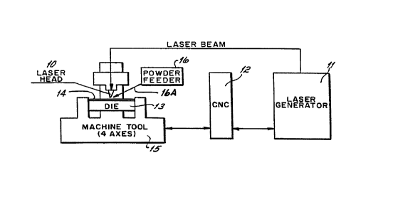
Turning now to the drawings, a diagrammatic illustration of
the apparatus and process for carrying out the invention is shown in Fig.
1. A C02 laser head 1 O and generator 11, controlled by a CNC 12, are
operationally interconnected. Such a COa laser head 10 and laser
generator 1 1 can be, for example, the laser components manufactured
by TRUMPF, Incorporated of Farmington, Connecticut according to its
mode! no. TLF 2600 turbo. The path and density of laser beam can be
controlled by the CNC 12. One such CNC is made by Boston Digital
Corp. of Boston, Massachusetts under the model no. BD85-2. The die
is mounted on a three, and preferably four, axis machine tool 15. One
r
such machine tool is made by Boston Digital Corp. under the model no.
BD85-2. Powder feeder 16 can be either a side feeder or coaxial feeder
which is preferable. Such a side feeder is manufactured by Sulzer Metco
(Wostbury, Inc) of Cincinnati, Ohio under model METCO Type 9MP. A
die cylinder 13 is shown with the blade 14 being formed therein. The die
cylinder is rotated by the machine tool 15, which is also controlled by the
CA 02245864 1998-08-11
WO 97/29879 PCT/US97/02482
- 11 -
CNC machine 12 to coordinate with the laser head 10 and the laser
generator 1 1. The powder feeder 16 is associated with the laser head
_ 7 _ ~.a. _ / _ _ ! _ J _ _ _ _ _I - - i L _ _ L - ! - 1 - _I
1 O, so as to Se~eczive~y W troauce powaer into ine area Qe~ng ciaa, as will
be described.
It will be appreciated that the movement of laser beam with
respect to die surface is controlled by CNC 12. Either laser head 10 or
die cylinder 13 moves along the path corresponding to the desired
configurations of the die blades to be extended therefrom.
Turning now to Fig. 2 there is illustrated a part of the
process of the invention. The laser beam 10 is scanned along the die
surface 13A, so as to melt or "puddle" an area 17 in the surface 13A,
along a path corresponding to the desired die blade pattern. Upon such
melting or puddling, the powder 16A is fed into the area being clad by
the laser so that in one pass along the surface 13A, as illustrated in Fig.
13, a die blade of half ellipse cross-sectional dimension is formed. The
material of the die body 13 is selected to conform to the desired_
parameters in the die body for toughness. Ordinary, medium carbon plain
steels or medium carbon low alloy steels such as 1045 or 4150 steel, for
example, may be used.
in contrast, the material which is preferably introduced in
powder form, to form the blade 14, may be of another material selected
based on the desired parameters of the die blade. This material can be a
CA 02245864 1998-08-11
WO 97/29879 PCT/US97/02482
- 12-
very high grade steel, such as CMP10V or CMP15V, or a metal-ceramic
composite, such as a nickel base superalloy plus 30-40% (volume
fraction) tungsten carbides.
Presently, the deposition of powder through a powder
nozzle, for example (not shown), forms a generally half ellipse cross-
sectional die blade 14 as illustrated in Fig. 3. It is preferable to have the
final die blade in a cross-sectional profile with edges which are
somewhat tapered such as, for example, at about 25° to about
35°.
Such die blade shapes, for example, are disclosed in U.S. Patent No.
4,608,895, which render the die blades suitable for contact with an
opposing die for cutting a work piece inserted therebetween.
Fig. 4 illustrates the desired final shape of the die blade 14.
In Fig. 4, it will be appreciated that areas 21, 22 and 23 have been
removed from the die blade 14, so the die blade 14 is of tapered or
truncated configuration in cross-section.
It will be appreciated that it is only necessary to remove the
relatively small areas 21, 22 and 23 to form the final die blade 14 from
the half-ellipse shape of the die blade as illustrated in Fig. 3. As a result
of the cladding process by which the die blade material is built up, the
die blade is formed integrally with the die body 13 and a metallurgical
bonding is produced between the die blade and the die body. Once the
CA 02245864 1998-08-11
WO 97/29879 PCT/US97/02482
-13-
blade 14 is finally shaped, as shown in Fig. 4, it can be readily used as
a cutting die.
It may be desirable to further harden the die blade and this
may be accomplished by any suitable technique, such as by raising the
die blade material to a temperature sufficient for further strengthening
that material and/or by cryogenic treating the clad tracks to eliminate the
remaining austenite in the cladding material. For example, the die blade
could be treated by scanning a laser beam along the die blades where the
parameter of the traverse speed and intensity are appropriate to produce
the optimum microstructures and hardness. It will be appreciated,
however, that by virtue of the use of very high quality steel in the
forming of the blade, such as those mentioned above, the optional heat
treating steps for strengthening die blade may be unnecessary.
Alternatively, Localized hardening might be accomplished. by induction
heating.
The final shape and size of the die blade are important. The
die blade must be high enough to provide the desired cutting of the
desired workpiece. For many applications, it has been found that a die
blade of approximately 1 .5 to 2.0 millimeters is high enough for a large
number and variety of applications. Where the die blade is to be tapered,
it has also been found that, after blade shaping, the top surface 14A of
the die blade, as shown in Fig. 4, will be approximately .035 inches
CA 02245864 1998-08-11
WO 97/29879 PCT/US97/02482
- 14-
wide. Such a die blade would be suitable for rotary pressure cuts, for
example. On the other hand, if it is desired to produce crush cut die
hlariac tha width of tho rain hlarlca tnn 1 d~ maar hn fnr ov~m.,i" n nnH
..........., ... ... ..... ~, . .... ~..,... ....... .......... «.~.. . T.~
...u ~. arar, . v. vr~a. "~,c, v.vv
0.002 inches.
It will be appreciated that the final shaping of the die blade,
as illustrated in Fig. 4, may be carried out by any suitable process. It is
preferred to use an electronic discharge machine (EDM) process to
remove the small amount of material necessary on each side of the die
blades. Of course, the die blades could be ground or milled into the
desired shape.
Turning now to the illustration of Fig. 5, there is shown a
die blade 14 formed according to the invention on a die surface 13A of
a die body 13. The phantom line 25 is used to contrast the process of
the invention with prior processes where the die blades were formed
integrally from the die body. For example, in a prior process, a die body
may have had an outer periphery 25. In order to form a die blade 14, it
was thus necessary to machine away or remove or relieve all the material
of the die body from periphery 25 down to a surface 13A, except for the
remaining blade material illustrated by the blade 14 in Fig. 5.
It will be appreciated that, according to the invention, the
starting material is a die body 13 having a surface 13A and that the die
blade 14 is built up as a feature on the die surface 13A. It is thus not
CA 02245864 1998-08-11
WO 97/29879 PCT/US97/02482
-15-
~ necessary to start with a cylinder having a periphery such as 25 and then
grind or remove away the material illustrated between the surface 13A
and the phantom line 25. Instead, the only shaping required is as
illustrated in Fig. 4, where final shaping of the sides of the die blade is
performed with only material designated at 21, 22 and 23 being
removed. It will also be appreciated that, as contrasted with the prior
processes, the die blade 14 can be formed of any suitable materials,
based on the desired parameters for the die blade itself, and is not
necessarily the same material as the die body.
Accordingly, very high grade materials can be utilized in the
formation of the die blades without purchasing an entire die cylinder
made of the same high grade and high cost steel.
Turning now to the process of this invention, it will be
appreciated that a laser of approximately two kilowatt or above is useful
in cladding or building up the die blade material. Die blades of
approximately two millimeters or somewhat greater in height may be_
produced in a single pass with such a laser. 6t would be possible to build
up the die blades by multiple laser passes assuming, of course, that the
intersections of the various layers did not present a usage or a wear
problem in the final die blade.
CA 02245864 1998-08-11
WO 97J29879 , PCT/LTS97/02482
- ~s -
It will also be appreciated that lasers of higher power could .
be utilized to build up die blades of significantly higher or greater depth
in a single pass, or blade metal with a higher melting temperature,
however, much higher performance lasers would be necessary and these
cost substantially more. The ability to manufacture cutting dies having
blades of exceedingly hard material and thereby increasing the useful life
of the cutting die, makes it unnecessary to produce die blades of such
height as a softer blade which would be required for a Large number of
reconditioning cycles. Presently, blades of otherwise unnecessary height
are the case with cutting dies manufactured of relatively lower grade
steels, even though they are hardened.
It should be appreciated that in this invention, a COz
laser which can locally melt die surface and powder. However, the laser
generation medium is not limited to C02 gas. Any other types of lasers
1 S which use different mediums could also be applied if they can generate
enough power.
Finally, it should be appreciated that in this invention, the
- blades can be built up via cladding using a heating source (laser beam)
and a cladding material supply (powder). However, the heating source
which is used to melt cladding material and die surface is not limited to
lasers. Any other heating sources which can quickly raise temperature
on the selected area could be used in this invention, for example, thermal
' CA 02245864 1998-08-11
I
- 1 7 -
spraying gun, ion beam, electron beam and plasma transfer arc, etc. On
the other hand, the cladding materials are not limited to powder. For
example, welding wire, gaseous materials, liquid materials, might be used
without departing from the scope of the invention.
AtVfENDED SHEET