Note: Descriptions are shown in the official language in which they were submitted.
CA 02245867 1998-08-06
WO 97/30333 PCT/US97/00941
-1-
FLOW METER WITHIN CAUSTIC FLUIDS HAVING
NON-CONTAMINATING BODY
BACKGROUND OF THE INVENTTON
. I. FIELD OF THE INVENTION
This invention relates generally to flow meters, and
more particularly, to a flow meter which may be connected
in-line within a chemically corrosive fluid flow circuit in
either a liquid or gaseous state, wherein the flow meter
includes two chemically inert pressure sensors that are
contained within a non-contaminating body on opposite sides
of a constriction and may be isolated from the fluid flow
circuit.
II. DISCUSSION OF THE RELATED ART
Frequently, caustic fluids are used in the processing
of sensitive materials. During the production of these
sensitive materials, the susceptibility to contamination is
a significant problem faced by manufacturers. The
manufacturers may, for example, process semiconductor
wafers using caustic fluids. Various manufacturing systems
have been designed to reduce the contamination of the
sensitive materials by foreign particles and generated
vapors.
The processing equipment used in the manufacturing
systems include designs that attempt to eliminate all
sources of damaging contaminants. The processing of the
sensitive materials often involves the direct contact of
the sensitive materials with the caustic fluids. Hence, it
is critical that the caustic fluids are delivered to the
processing site in an uncontaminated state. Various
components of the processing equipment are commonly
designed to reduce the amount of particulate generated and
to isolate the processing chemicals from contaminating
w inf luences .
Liquid transporting systems carry the caustic
chemicals from supply tanks through pumping and regulating
stations and through the processing equipment itself. The
liquid chemical transport systems, which includes pipes,
CA 02245867 1998-08-06
WO 97/30333 PCTILTS97/00941
-2-
tubing, monitoring devices, sensing devices, valves,
(fittings and related devices, are frequently made of
plastics resistant to the deteriorating effects of the
toxic chemicals. Metals, which are conventionally used in .
such monitoring devices, cannot reliably stand up to the
corrosive environment for long periods of time. Hence, the
monitoring and sensing devices must incorporate substitute
materials or remain isolated from the caustic fluids.
The processing equipment commonly used in
semiconductor manufacturing has monitoring and sensing
devices, such as pressure sensors and flow meters. These
monitoring and sensing devices are connected in a closed
loop feedback relationship and are used in monitoring and
controlling the equipment. These monitoring and sensing
devices must also be designed to eliminate any
contamination which might be introduced. For example, a
turbine flow meter known in the art has moving parts that
wear out and become corrupted when exposed to the caustic
fluids. Further, these turbine flow meters tend to trap
fluid that contaminate subsequent process fluids. In
avoiding the use of turbine flow meters, the monitoring and
sensing devices may incorporate sensors. These devices
must also be designed to avoid the introduction of
particulate, unwanted ions, or vapors into the processing
steps.
The general use of pressure sensors in flow meters is
known in the art. For example a venturi, nozzle, orifice, ,
or weir meter may be used for measuring or controlling the
rate of flow. A differential sensor or pitot tube with
sensors may be used, however, both these arrangements
require small ports or capillaries that can easily plug or '
trap contaminants. The prior art does not disclose a flow
meter which may be positioned in-line within a fluid flow
circuit carrying corrosive materials, and which does not
contaminate the processing fluids. Hence, a need exists
for a flow meter having non-contaminating pressure sensors
which may be positioned in-line within a fluid f low circuit
CA 02245867 1998-08-06
WO 97/30333 PCT/US97100941
-3-
carrying corrosive material. Also, a need exists for a
flow meter, wherein the accuracy of the flow meter is not
affected by thermal changes within the fluid flow circuit.
Mechanical processing equipment handling fluids are
often subject to potential leakage and such leakage can
create extremely hazardous conditions, both to the
processing of the sensitive materials or other products and
also to personnel who may have to tend and maintain the
processing equipment. Hence, the chemical transport system
must be designed such that leakage is avoided.
An in-line mechanical fluid pressure responsive gauge
separated from the fluid flow by a protective membrane is
known in the art. The gauge is contained within a housing
having a cavity filled with a sensor fluid. The cavity is
formed adjacent the fluid flow and separated by the
protective but flexible membrane. The sensor fluid
contained within the cavity is typically a silicone oil.
A change in pressure within the fluid affects the silicone
oil pressure within the cavity. The oil pressure is
detected by the mechanical pressure responsive gauge.
The fluid within the cavity typically has large
coefficient of thermal expansion, which may cause a
significant deflection in the membrane. The large
deflection changes in the protective membrane increases the
likelihood that the fluid within the cavity will leak into
the fluid flow, contaminating the flow circuit. Also, the
accuracy of the pressure gauge is negatively affected by
the large thermal expansions of the sensor fluid. Hence,
a need exists for an in-line pressure gauge that does not
leak contaminating fluids into the fluid -flow circuit.
' Also, a need exists for a pressure gauge, wherein the
accuracy is not affected by thermal changes within the
' fluid flow circuit.
Collins et al., in U.S. Patent No. 5,316,035 (the '035
patent) describes the use of a capacitance proximity
monitoring device in corrosive atmosphere environments. In
one embodiment of the '035 patent, the capacitance
CA 02245867 1998-08-06
WO 97/30333 PC'd'/L1S97/00941
-4-
proximity device is described as being incorporated into a
functional apparatus, such as a piping system including .
valves and couplings. The capacitance proximity device
serves as a functional portion of the apparatus and creates
a sensing region within a predetermined area. It i.s then
used to determine the change of electrical characteristics
within the predetermined area as various fluids flow past
the predetermined area. Monitoring changes in the current
related to the sensing field when the liquid target media
is present, versus air or gas in the piping when the liquid
target media is absent, thereby produces an indication of
the presence or absence of the target media. The complex
valving is used to control fluid flow and the possibility
exists that the fluid will leak and contaminate the
processing fluid flow.
None of the above identified prior art discloses or
even considers a device capable of determining the fluid
flow rate within the caustic chemical transport system of
chemical processing equipment. Further, none of the above
identified prior art discloses a device that determines
either or both the fluid flow rate and the pressure within
the fluid flow. Monitoring the fluid flow within the
chemical transport system is useful for several reasons.
First, a change in flow within the system may be indicative
of leakage within the system. Second, the flow within the
transport system is regulated to avoid exceeding
predetermined safety limits. Third, a change in fluid flow
may indicate an obstruction or infiltration of contaminants
into the fluid flow circuit.
Therefore, a need exists for a non-contaminating fluid
flow meter which may be positioned in-line within a fluid
flow circuit carrying corrosive materials, wherein the f low
meter determines the rate of flow based upon a pressure
differential measurement taken in the fluid flow circuit,
wherein the determination of the rate of flow is not
adversely affected by thermal changes within the fluid flow
circuit. A need also exists for a flow meter that avoids
CA 02245867 1998-08-06
WO 97/30333 PCT/LTS97/00941
_5_
the introduction of particulate, unwanted ions, or vapors
into the flow circuit. The present invention addresses
these needs.
SUMMARY OF THE INVENTION
The purpose of the present invention is to provide a
flow meter that may be coupled in-line to a flow circuit
transporting corrosive fluids, where the. rate of flow may
be determined from a differential pressure measurement
taken within the flow circuit. The flow meter includes two
pressure sensors contained within a non-contaminating body,
wherein the pressure sensors are separated in the flow
circuit by a constricting member.
The flow meter compensates for changes of temperature
within fluid flow circuit and provides a zeroing feature
which compensates for differences in pressure between the
two sensors when the fluid is at rest. In the preferred
embodiment, the components of the flow meter include a
housing, a cover, an electrical connector, pressure
fittings, isolation membranes, sealing rings, two pressure
sensors, a circuit board and electronic circuitry, spacer
rings and hold down rings.
The flow meter's housing has a bore extending
therethrough, which forms a passage or conduit through
which fluids flow, when the housing is connected in-line in
a fluid flow circuit. Aligned and sealably connected to
the opposed open ends of the bore are pressure fittings.
The pressure fittings are constructed from a chemically
inert material and are readily available and known to those
skilled in the art.
The housing also has two pressure transducer receiving
' cavities extending from an external surface thereof,
wherein each such cavity communicates independently with
' the bore. In the preferred embodiment, the bore tapers to
a constricting region located between the two cavities.
The restricted region results in a pressure drop within the
bore across points adjacent the two cavities. This change
in pressure may be detected by pressure sensor transducers
- , CA 02245867 2000-12-21
WO 97/30333 PCT/US97/00941
_6_
placed within each of the two cavities. The rate of flow
is determined from the change in pressure. The
determination of the rate of flow using the two pressure
sensors is discussed below.
An isolation membrane, pressure sensor, sealing
members, spacer ring and hold down ring are contained
within each cavity of the housing. These comz~onents and
variations thereof are discussed in-.U.S. Patent No.
5,693,887 issued December 2, ]997.
A hybrid or fully integrated electronic circuit
disposed in the housing is operatively coupled to both
pressure sensor transducers and to an electrical connector
contained in the cover. The electronic circuit develops a
signal which is a measure of the rate of flow within the
flow circuit from information sensed by both pressure
sensors. Further, the electronic circuit may develop a
signal corresponding to one or the other of the downstream
or upstream static pressures within the fluid flow circuit,
such that the orientation of the flow meter within the flow
circuit is interchangeable and the direction of flow may be
indicated by comparing the sensed pressure from each
pressure sensor. When sensing the static pressures of
gases flowing through the flow circuit, a correction may be
made to the sensed pressures to correct for non-linearities
as a result of gas density differences.
This electronic circuit may also be used in
combination with temperature sensitive components to adjust
the pressure measurement associated with each cavity based
upon temperature changes within the flow circuit. Further,
a switch may be incorporated into the electronic circuit
that allows zeroing of the flow meter by the user.
The electronic circuit is coupled by electrical leads
to the electrical connector and power may be transmitted to
the electronic circuit through the electrical leads mating
CA 02245867 1998-08-06
WO 97/30333 PCTlLTS97/00941 _
at the connector with an external power supply. Further,
an analog output such as a standard 4-20 milliamps signal
proportional to the calculated rate of flow may be
transmitted through additional electrical leads.
In an alternate embodiment, the housing comprises two
symmetric -housing halves. Each housing half includes a
longitudinal bore and counter bore for receiving a
restriction member therein. In another embodiment, a
portion of the longitudinal bore disposed between the two
cavities has a third cavity which receives a removable
insert. The insert has a channel extending therethrough,
thereby forming a passage from one bore section to the
other. In yet another alternate embodiment, a bushing is
friction fit within the bore between the two cavities to
thereby create the constriction. In a further alternate
embodiment, inert sapphire pressure transducers are
positioned within respective cavities and in direct contact
with the fluid flow, thereby eliminating the isolation
membrane.
OBJECTS
It is accordingly a principal object of the present
invention to provide a non-contaminating flow meter adapted
to be connected in-line in a fluid flow circuit.
Another object of the present invention is to provide
a flow meter, wherein inert pressure sensor components of
the flow meter may be situated in direct contact with-the
fluid flow.
Yet another object of the present invention is to
provide a flow meter having isolation members that are in
direct contact with the associated pressure sensors, the
isolation members acting to isolate the sensors and
associated electronic circuitry from potentially corrosive
' processing chemicals and precluding introduction of
contaminating substances into the processing fluids being
transported.
Still another object of the present invention is to
provide a flow meter, wherein a pressure of the flow
CA 02245867 1998-08-06
WO 97/30333 PCTIUS97/0094I
_g_
circuit is measured non-intrusively at two independent
points within the flow circuit to thereby determine the ~
rate of flow within the flow circuit.
A further object of the present invention is to
provide a non-contaminating flow meter that compensates for
initial pressure differences between the two pressure
sensor transducers when the flow rate is zero.
Yet another object of the present invention is to
provide a non-contaminating, chemically inert flow meter
l0 that determines either the rate of flow or pressure within
the fluid flow circuit.
These and other objects, as well as these and other
features and advantages of the present invention will
become readily apparent to those skilled in the art from a
review of the following detailed description of the
preferred embodiment in conjunction with the accompanying
drawings and claims and in which like numerals in the
several views refer to corresponding parts.
DESCRIPTION OF THE DRATnTINGS
Figure 1 is a side elevational view of the flow meter
made in accordance with the present invention;
Figure 2 is a top plan view of the flow meter of the
type shown in Figure 1;
Figure 3 is a partial sectional side elevational view
of the flow meter of the type shown in Figure 1;
Figure 4 is an enlarged, partial sectional side
elevational view of an alternate embodiment of the flow
meter with the cover and electric circuit removed;
Figure 5 is an enlarged, partial sectional end
elevational view of an alternate embodiment of the flow
meter; '
Figure 6 is an exploded view of the flow meter shown
in Figure 5; "
Figure 7 is a side elevational view of an alternate
embodiment of a flow meter in accordance with the present
invention;
Figure 8 is a partial sectional side elevational view
CA 02245867 1998-08-06
WO 97/30333 PCT/tJS97/00941
_g_
the f low meter of the type shown in Figure 7 with the
pressure transducer, electronic circuit, isolation membrane
hold down ring, spacer ring and seals removed for clarity;
Figure 9 is a top plan view of the flow meter of the
type shown in Figure 8, with the cover and electric circuit
removed;
Figure 10 is an enlarged sectional view of a
restriction member used in the embodiment of Figure 8;
Figure 11 is a partial sectional side elevational view
of another embodiment of a flow meter housing in accordance
with the present invention; and
Figures 12 and 13 together is a schematic diagram of
the electric circuit used in a flow meter in accordance
with the present invention.
DETAILED DESCRIPTION OF THE PREFERRED EMBODTMENT
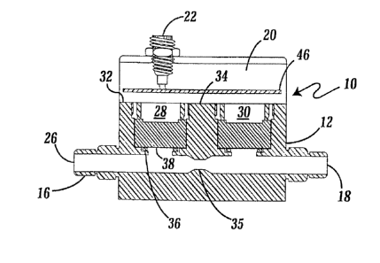
Referring first to Figures 1 and 2, the flow meter is
generally idenEi~ied by numeral 10-.- T'he- f5~ova meter 10
generally includes a housing or body 12, mounting fastener
slots 14, pressure inlet/outlet fittings 16 and 18, and a
cover 20. An electrical connector 22, of known
construction, may be removably attached in the cover 20.
The housing 12 and cover 20 are preferably manufactured
from a chemically-inert, non-contaminating polymer such as
polytetrafluoroethylene (PTFE). The cover 20 has bores 24
extending through it for mounting the cover 20 to the
housing 12 with appropriate screws (not shown). A suitable
gasket (not shown) is preferably positioned between the
cover and housing to allow the cover 20 to be sealed to the
housing 12. Without any limitation intended, a gasket or
seal manufactured from a mufti-layer fabric, sold under the
GOR-TEX~ trademark by W.L. Gore & Assoc., Inc., allows
venting of an internal area of the housing 12 for true
- atmospheric pressure reference, while restricting the f low
of liquids into the internal area of the housing 12.
Referring to Figures 3-6, the internal construction of
the flow meter 10 is shown. A longitudinal bore 26 extends
through the housing 12 forming a conduit. Thus, when the
CA 02245867 1998-08-06
WO 97/30333 PCT/US97/00941
-IO-
flow meter 10 is connected in-line with a fluid flow
circuit (not shown),~via pressure fittings 16 and 18, the
bore 26 serves as the fluid flow passage within the fluid
flow circuit. The orientation of the flow meter 10, within
the fluid flow circuit, may be reversed without affecting
its effectiveness.
First and second transversely extending cavities 28
and 30 extend all the way from an outer surface 32 of the
housing 12 to the bore 26. Those skilled in the art will
appreciate that cavities 28 and 30 may each extend into the
housing from a different sidewall of the housing. The two
cavities 28 and 30 are separated a predetermined distance
by dividing wall 34. The bore 26 also includes a
constriction or restriction 35 located between the two
cavities 28 and 30. Near the region within the housing
where each cavities 28 and 30 and bore 26 intersect, an
annular lip 36 is formed. Each lip 36 surrounds and
further defines the opening to each cavity 28 and 30 from
the bore 26.
A thin flexible polymer disk or isolation membrane 38
is positioned on the lip 36 of each cavity 28 and 30.
Without limitation, the membrane is preferably constructed
to have a thickness in a range between .001 and .040
inches. The upper surface of membrane 38 is abraded so as
to create a pattern of grooves or channels. Preferably,
the flexible membrane 38 is manufactured from
tetrafluoroethylene fluorocarbon polymers. One such
tetrafluoroethylene fluorocarbon polymer is sold under the
TEFLON~ trademark by E.I. duPont Nemours.
The isolation membranes 38 may have a t;-.z.n film formed
on its surface, to act as a buffer to any caustic chemicals
leaking into the pressure transducer cavities. The thin
film may further act as an electric shield for capacitance '
sensors, thereby obviating inaccuracy problems resulting
from changes in dielectric properties as fluids flow
through the flow meter. The thin film may for example be
a carbon powder and epoxy ink painted onto the isolation
CA 02245867 2000-12-21
WO 97/30333 PCT/US97/00941
-11-
membrane 38 or a thin film of carbon may be surface molded
into the isolation membrane. The coated disk membrane 38
is preferably molded, since spraying or manufacturing by
some other process may leave pinhole paths therein.
Alternatively, the isolation membrane may be reinforced
with carbon fibers, thereby increasing the elastic behavior
of the isolation membrane 38, and reducing the cold flow
tendencies of the PTFE isolation membrane.
When the flow meter 10 is fully assembled, the annular
surface contact between each flexible membrane 38 and each
cavity's lip 36 is such that a hermetic seal is formed
therebetween. Various features of each lip 36 and
isolation membrane 38, without any limitation intended, may
be altered as described in the aforementioned U,S. Patent
VQ, 5,693,887.
Each pressure transducer 42 and 44 is held in place
within their respective cavities 28 and 30 by spacer ring
48 and externally threaded hold down ring 50. The
isolation membranes 3;8 and transducers 42 and 44 are sealed
within the housing 12 by chemically inert o-ring seals 52
and 54. A redundant seal is created by the positioning of
o-rings 52 and 54. The seals 52 and 54 are readily
available and of known construction to those skilled in the
art . An additional spacer ring 56 (see Figure 4 ) may be
necessary, depending upon the dimensions of the pressure
transducer.
A drain or conduit 40, shown in Figures 5 and 6, may
be formed extending through the housing wall 32 into each
cavity 28 and 30 between the redundant seals 52 and 54,~
thereby draining the area between the redundant seals. In
this manner, the drain acts as a drainage, passageway or
outlet, in the event that fluids leak past seal 52 from the
fluid flow circuit. A sensor 41 is positioned within the
drain 40 and is electrically connected (by leads not shown)
to the electric circuit 46. Those skilled in the art will
appreciate that a conductive sensor, capacitive sensor or
non-electric fiber optic sensor may equally be used to
CA 02245867 1998-08-06
WO 97/30333 PCT/LTS97/00941
-12-
sense the presence of fluids in the drain 40. When fluid
leaks past the first seal, the fluid activates the sensor -
41, thereby transmitting a signal to the electric circuit
46 which subsequently sets off an alarm. ,
The redundant sealing arrangement helps prevent
exposure of the pressure transducers 42 and 44 and electric
circuit 46 from the damaging affects of the caustic fluids.
The redundant seal also further isolates the fluid flow,
thereby reducing the potential contamination of the fluids.
Additionally, a tube (not shown) may be connected to the
drain 40, to thereby carry away the caustic fluids to a
non-contaminating area.
Ref erring again to Figures 3 and 4, the pressure
sensors 42 and 44 are positioned on top of the associated
flexible isolation membrane 38. Each pressure sensor may
be of a capacitance type or piezoelectric type known to
those skilled in the art. The base of each pressure sensor
is in direct contact with the membrane 38 and may be either
in pressure contact with or bonded to the membrane by an
adhesive, thermal welding or by other known means. The
base may have a carbon film formed thereon, to act as an
additional shield against potential leakage and further to
act as electric shield.
In one embodiment, an alumina ceramic pressure sensor
may be used, wherein the alumina ceramic pressure sensor
comprises a thin, generally compliant ceramic sheet having
an insulating spacer ring sandwiched between a thicker, .
non-compliant ceramic sheet. The first thin ceramic sheet
or diaphragm is approximately .005 to .050 inches in
thickness with a typical thickness of .020 inches. The
thicker ceramic sheet has a thickness range between .100 to '
.200 inches. The spacer ring may be constructed of a
suitable material such as a glass, polymer or alternatively '
the ceramic sheets may be brazed together. The opposed
faces of ceramic disks are metalized by metals such as
gold, nickel or chrome to create plates of a capacitor. A
similar capacitive pressure transducer is described by Bell
CA 02245867 1998-08-06
WO 97/30333 PCT/US97/0094I
-13-
et al. in U.S. Patent 4,177,496 (the '496 patent). Other
capacitive pressure transducers similar to that described
in the '496 patent are available and known in the art.
It is contemplated that the flexible membrane 38 could
be eliminated if the pressure sensor used is of the
sapphire capacitive pressure transducer type. A sapphire
transducer is inert, and is resistant to wear when
subjected to caustic fluids. Having a sapphire sensor in
direct communication with the fluid flow, further enhances
the pressure measurements of each transducer.
Referring next to Figures 7-9, an alternate embodiment
of the flow meter's housing 12 is shown. The housing 12 is
split into two sections or halves 58 and 60, wherein the
downstream section 58 has a cavity 62 and longitudinal bore
66, and upstream section 60 has a cavity 64 and
longitudinal bore 68 formed therein. The longitudinal
bores 66 and 68 of each section 58 and 60 respectively,
have respective counter bores 70 and 72. The two sections
58 and 60 are aligned and engaged, such that the counter
bores 70 and 72 are aligned, thereby forming a hollow
cavity in which a restriction member 74 is inserted (see
Figures 8 and 9). The restriction member 74 has a central
opening 76 extending therethrough (see Figure 10), which is
aligned with the longitudinal bores 66 and 68. The
restrictions central opening 76 is smaller in diameter than
either section's longitudinal bores 66 and 68. The
restriction member 74 is sealably engaged with each housing
section"s bore 66 and 68 by chemically inert sealing o-
rings known in the art. Without any limitation intended,
the restriction member 74 and associated sealing rings are
preferably constructed of polytetrafluoroethylene.
Referring now to Figure 11, yet another alternate
embodiment of the housing 12 is shown. In this embodiment,
a third cavity 78 extends from a bottom outer surface of
the housing 12 and into communication with the bore 26.
The third cavity 78 is formed midway between the first and
second cavities 28 and 30_ A replaceable insert or plug
CA 02245867 1998-08-06
WO 97/30333 PC~'BJS97/0094I
-14-
80 is inserted and sealed within the third cavity 78. The
plug 80 has an opening or channel 82 (not shown) extending -
therethrough, wherein the channel 82 is aligned with the
longitudinal bore 26, thereby forming a passage from one
bore section to the other. It is contemplated that the
third cavity 78 may extend from a top outer surface of the
housing 12. In this arrangement, once the cover 20 is
sealed to the housing 12, external access to the third
cavity 78 would be limited.
The diameter of the channel 82 is less than the
diameter of either bore section 26, thereby creating the
constriction or restricted region. The plug 80 engages
with the third cavity 78, by chemically inert o-rings 84
known in the art. Without any limitation intended, the
plug 74 and sealing rings 84 are constructed of
polytetrafluoroethylene, wherein the sealing rings 84 seal
the plug 74 within the third cavity 78. The plug may
alternatively be constructed of sapphire, a material
resistant to wear from the fluid flow.
In another alternate embodiment the constriction 35 is
formed by a bushing that is friction fit between the
cavities 28 and 30. Of course, the bushing includes a bore
of smaller cross-section than longitudinal bore 26, which
interconnects the remaining bore sections. Those skilled
in the art will appreciate that the constriction 35 may be
created by a variety of forms including those discussed
above. The constriction may be constructed of sapphire,
thereby extending the longevity of the flow meter. Those
skilled in the art will appreciate that sapphire is an
inert substance, highly resistant to wear from caustic
flowing fluids.
Those skilled in the art will appreciate that the
cavities and housings of each embodiment are dimensioned to
universally accept the same pressure fittings 16 and 18,
cover 20, isolation membrane 38, pressure sensors 42 and
44, electronic circuit 46, spacer ring 48, and hold down
ring 50. Also, each embodiment has a constricting area of
CA 02245867 1998-08-06
WO 97!30333 PCT/US97/0094I
-15- ._
varying construction between the sensor receiving cavities
to create a pressure drop as the fluid flow traverses the
restriction.
Referring again to Figure 3, the electronic circuit
module 46 is positioned above the ceramic pressure
transducers 42 and 44 and is electrically coupled to the
conductive surfaces of the ceramic pressure transducers 42
and 44. The electronic circuit module 46 is also connected
by suitable leads (not shown) to internal contacts of the
connector 22 (Figure 1). In the preferred embodiment the
electrical connector 22 is made of a chemically inert
material and preferably may be of a type available from
Pneumatico, part number po3rsd-00004-24.
Referring to Figures 12 and 13, there is shown an
electrical circuit schematic diagram of the electronic
circuit module 46. The electronic circuit is used to
convert the pressure readings from the two pressure
transducers 42 and 44 to a 4-20 mA analog representation of
flow or, alternatively, a pressure reading of the
downstream pressure transducer 44. The raw analog signal
from the upstream transducer 42 is supplied to input
terminal 102 and, likewise, the raw analog transducer
output signal from the downstream transducer 44 is supplied
to the input terminal 104. Terminals 106 and 108 are power
input terminals and terminals 110 and 112 are connected to
the ground bus 114 (see Figure 12).
Connected between the +5 volt power bus 116 and the
ground bus 114 is an analog temperature compensation chip
118 which may preferably comprise a type LM 45 device
available from National Semiconductor, Inc. The
- temperature compensation chip 118 has its v' terminal
connected by conductor 120 to the +5v bus 116 and its v
input connected through a semiconductor diode 122 to the
ground bus 114. The diode 222 provides an offset, so that
the signal proportional to temperature produced on output
terminal 124 of the temperature compensation chip 118 can
go below 0°C, i.e., assuming a negative value.
CA 02245867 1998-08-06
WO 97/30333 PCT/LTS97/00941
_16_
The raw sensor signals produced on input terminals 102
and 104, together with the temperature compensation signal
produced at terminal 124 are individually applied to a four
channel sigma delta type analog to digital (A/D) converter
chip 126. The chip 126 may preferably comprise an AD7714
integrated circuit chip supplied by Analog Devices
Corporation. Those wishing details of the mode of
operation of that integrated circuit are referred to the
data sheets available from Analog Devices Corporation.
The sigma delta A/D converter 126 includes a digital
filtering capability for the analog pressure inputs where
the cut off frequency of the low pass filter is a
programmable quantity set by the software executed in the
microprocessor chip 128. Without limitation, the
microprocessor 128 may comprise a type PIC 16C73 integrated
circuit available from Microchip Technology Corporation.
T'hA ra~~at'~tra irnl tagP di tri_r3ar i _n_rl pdi ng raa~a'~y ~ i~~} and
132, which are connected between the positive bus 116 and
the ground bus 114, provide voltage compensation when the
pressure data is being linearized.
The A/D chip 126 provides its serial output data
stream on line 134 to a data input terminal 136 on the
microprocessor 128. The serial data from the A/D converter
chip 126 is clocked out, under control of timing signals
provided by a crystal controlled clock circuit indicated
generally by numeral 138. This clock circuit 138 also
provides timing pulses over line 140 to the clock input
terminal 142 of the microprocessor chip 128 for controlling
its timing.
The microprocessor 128 is programmed to compute~the
instantaneous pressure differences being picked up by the '
upstream and downstream transducers 42 and 44 and to
perform any necessary zeroing adjustments and scaling. A '
switch 143 is connected to the microprocessor 128. When
switch 143 is switched to the on position, the difference
in pressure between the two sensors 42 and 44 is
calculated. This value is then stored. Typically, the
CA 02245867 1998-08-06
WO 97/30333 PCTlUS97/0094I
_17_ ..
user will activate switch 143 to test mode when there is no
. fluid flow. Any difference in pressure during no fluid
flow will be stored in the microprocessor. The user then
de-activates the switch 143. During fluid flow, the stored
value is subtracted from the difference in pressures,
thereby performing the zeroing adjustment. A test is also
made to determine whether the thus scaled pressure
difference is above or below preestablished high/low
limits. If the pressure difference is above or below the
pre-established high/low limits, an alarm is activated.
When the pressure difference is within the preestablished
limits, the rate of flow. is computed.
It is known that, in steady-state flow, the flow rate
is the same at any point. The flow rate (I) may be
expressed as I", = pvA. Where p represents the density of
the fluid, v represents the velocity of the fluid, and A
represents the area through which the fluid travels. Using
the continuity equation Alv1=AZv2, the rate of flow within
the flow meter 10 may be found to be equal to a constant
multiplied by the P1-P2. The microprocessor 128 thus
computes the rate of flow from the data received from the
two pressure sensors. Those skilled in the art will
recognize that with laminar flow, the rate of flow
approximates more closely a constant multiplied by P: - P;.
Hence, a low flow limit could be built into the system,
such that if the "Reynolds number" is below a certain
threshold, the flow meter identify the flow rate as zero.
Figure I3 illustrates the circuitry used to convert
the rate of flow computed by the microprocessor 128 into an
analog signal falling in the range of from 4mA to 20mA for
- use by existing analog control systems. That is to say,
the digital value of flow computed by the microprocessor
- 128 is converted to an analog signal whose current
amplitude is directly proportional to the computed flow
value and is in the range between 4mA and 20mA.
In addition to providing an analog current in the
4mA to 20mA range indicative of flow, the system may also
CA 02245867 1998-08-06
WO 97/30333 PCT/US97/00941
_18_
be used to provide a 4 mA-20 mA current signal proportional
to the pressure sensed by the downstream transducer 44 or
upstream transducer 42. More particularly, as seen in
Figure 13, the circuitry is partitioned into substantially
identical upper and lower channels where the 4mA to 20mA
current signal proportional to flow becomes available
across the output terminals 144 and 146, and the 4mA - 20mA
current signal proportional to pressure becomes available
across the output terminals 148 and 150.
Referring back to Figure 12, the microprocessor 128
provides a clocking signal on line 152 which connects to a
corresponding line 152 in Figure 13. Likewise, first and
second data output lines 154 and 156, respectively, coming
from the microprocessor 128 connect to the corresponding
lines 154 and 156 at the left hand side of the schematic
Figure 13. Signals for determining which of the two
channels in Figure 13 is to be operative is also provided
by way of a digital to analog converter chip select signal
emanating from the microprocessor 128 on line 158. This
signal is provided to an opto isolator circuit 160 and 162
whose output goes to the "chip select" terminal on either
the digital-to-analog (D/A) converter chip 164 or the
digital-to-analog chip 166. In each case, the D/A
converters 164 and 166 may comprise a Z2 bit device, such
as a type MAX538 D/A converter chip available from Maxim
Corporation.
As can be seen from Figure 13, the clock signals on
line 152, as well as the data signals on Lines 154 and 156,
are also optically isolated via opto couplers 168, 170,
172, and 174 with the resulting signals being applied to
the respective D/A converters.
The circuitry to the right of the vertical-line 176
functions to convert the analog signal output, from either '
the digital to analog converter 164 or the digital to
analog converter 166, to a current signal in the range of
from 4mA to 20mA depending upon the amplitude of the
voltage output from the D/A converters 164 and 166. As can
CA 02245867 1998-08-06
WO 97/30333 PCTICTS97/00941
-19-
be seen, the output from the D/A converter 164 is coupled
through a resistor 178 to the non-inverting input of an
operational amplifier 180. The inverting input thereof is
connected to ground 194. The output of the operational
amplifier 180 is connected to the gate electrode of a FET
device 182 as are bias resistors 184 and 186.
A voltage reference for the FET device 182 and for the
D/A converter 164 is obtained by means of series connected
diodes 188 and 190 which are connected in series across the
positive voltage bus 192 and the ground bus 194. In that
the voltage to current converter circuitry associated with
the D/A converter 166 illustrated to the right of the
vertical line 176 is substantially identical to what has
already been described in association with the D/A
converter 164, it is deemed unnecessary to repeat that
description.
The output lines 196 and 198 shown coming from the
microprocessor 128 in Figure 12, are applied via
corresponding numbered lines in Figure 13 to an opto
coupler 200. The output from the opto coupler 200
indicates that power is present on lines 144 and 146 and
also on lines 148 and 150.
Referring back to Figure 12, the microprocessor chip
128 has associated with it a RS232 serial port indicated
generally by numeral 202. As such, the flow meter device
of the present invention is capable of communicating with
a variety of peripheral devices including a further central
processing unit (not shown). The electronic circuit 46 may
also adjust the pressure and flow output as the temperature
within the flow circuit changes by including a thermistor
- or like component therein. Each pressure transducer is
corrected for temperature independently. One means of
' temperature compensation is disclosed in U.S. patent
4,598,381.
In use, the user couples the flow meter 10 into a
fluid flow circuit through pressure fittings 16 and 18. As
fluid flows through the flow circuit, the pressure adjacent
CA 02245867 1998-08-06
WO 97/30333 PCT/US97/00941
-20-
each of the two cavities is detected by the electric
circuit 46, whereby the rate of flow is calculated from the
two detected pressures. The gauge pressure or absolute
pressure may equally be used. From the determination of
the flow rate, an alarm is activated if the flow rate or
downstream pressure increases or decreases above or below
predetermined limits, or the processing equipment is turned
of f .
Those skilled in the art will recognize that the flow
rate may be calibrated so that minimum desired output
values axe associated with minimum pressure and maximum
desired output pressures are associated with maximum
pressure. For example, a pressure sensor intended to
measure 0 to 100 psig (pounds per square inch gauge) can be
calibrated to read 4mA (milliamps) at 0 psig and 20mA at
100 psig.
By providing the inert Teflon isolation membrane in
intimate contact with the pressure sensors, the working
fluid does not contact the surfaces of the sensor which
could lead to contamination. The sealing arrangements
disclosed, ensures that the working fluid does not enter
the cavities of the housing 12 and adversely affect the
electronic circuitry 46.
This invention has been described herein in
considerable detail in order to comply with the patent
statutes and to provide those skilled in the art with the
information needed to apply the novel principles and to
construct and use such specialized components as are
required. However, it is to be understood that the
invention can be carried out by specifically different
devices, and that various modifications, both as to the '
equipment details and operating procedures, can be
accomplished without departing from the scope of the '
invention itself.