Note: Descriptions are shown in the official language in which they were submitted.
CA 02245998 2003-07-04
1
TITLN OF THE INVENTION:
port closure for a tank
G~
FIBLD OF THE INVE3~ITIOhI
The present invention relates to a port closure fox
1C storage and t_raneport taa~.ks arid, i.n particular a port c:Losure
that can with:~tand a pressure differential.
HACKC-~R0~7ND OF' THE INVE1 ION
Every storage tank and transport tank has an access pert.
7.5 The access port may bE~ large enough for a person to enter for
t;he purpose of inspecaing the interior of the tank or the
access part may be only large enough to permit the passage of
matter into the tank. With some commodities it is ~.mportarit
that the tanks have pvrt closures that can withstand a pressure
20 differential between internal and external pressure. For
example, in tanks used for the storage or transportation of
granular or powder foam dry bulk goods (such as, flour, salt,
cement, lime, and cereal grains) the contents are pneumatically
transferred. Pneumatic transfer systems do not work properly
25 unless the closure on the access port can maintain a pressure
differential between interior pressure and exterior pressure.
The port closures :in common u.se ~fvr such applications at
the present time consist of an external lid. This external lid
30 is held in position by a series of camlocks spaced evenly about
a circumferen~;e of the access port. These closures have a
number of problems. A first problem is that they are prone t:o
leakage. A ser_ond prob':..em is that t:r~e camlocks must be manually
xe~.eased. This requires a person tc~ climb up onto the tank, and
35 creates a potent7.al safety hazard. The severity of the hazard
depends upon the hei~:~r~.t, of the ta~ak, J.~.g:hting conditions,
weather conditions (w.ind, rain, etc), and other surrounding
CA 02245998 1998-08-26
2
circumstances. A third problem is that carp must be taken to
ensure that the pressure within the interior of the tank is
released prior to attempting to open t:he closure. If a
pressure differential exists, she closure will open under
pressure with a vio-gent force. This violent opening force has
resulted in a number of injuries and deaths as the person
opening the closure has been struck by the closure and, in some
cases , knocked c>f f of the tank .
SUMMARY OF THE INVENTION
What is required is an alterna~=ive form of port closure
for a tank.
According t.o the present invention there is provided a
port closure fir a tank. The port closure involves a
combination wh_i.c:h includes a tank, a closure member and an
actuator. The tank has defining walls, an exterior surface,
an interior su~-'ace~, an interior cavity and an access port .
The closure memx~er is disposed within the interior cavity of
the tank. The r.~losure member has an access port engaging face
that is larger than a cross-sectiona=L area of the access port.
The actuator is coupled with the closure member and moves the
closure member between a first position in which the access
port engaging fare closes the access port and a second position
laterally spaced from the access port.
The port closure, as described above, provides a number
of advantages over an externally applied cam-lock lid. As the
port closure is ins>talled within the interior cavity of the
tank, internal ~re:~sure within the tank tends to press the
closure member against the accedes port; thereby reducing the
possibility of :Leakage. The port. closure is moved between the
first position clos=i.ng the access port and the second position
by the actuator. There is no need Eor the closure member to
be manually opened. This virtualr_y eliminates the safety
hazards formerly associated with opening and closing the access
port.
CA 02245998 1998-08-26
3
There are various forms of actuators that can be used for
the remote actuation of the closure member. 'rhe preferred form
is a telescopi.<~ally extendible mernber. For example, the
telescopically ~~xte~ndible member can consist of a cylinder
connected by f:::~uid. lines to a fluid control system that
controls the supply of fluid to the c°ylinder to telescopically
expand and cont:l-act said cylinder. This enables the closure
member to be me>~red between the first positv~on and the second
position either hzrdraulically or pneumatically. With a
transport tank, the hydraulic or pneumatic lines can be run off
of the hydraulic.: or ;pneumatic systems of the t ransport vehicle .
Although beneficial results ma,r be obt:ained through the
use of a port cl:~sux-e, as described above, such a port closure
can only be instal:Led in a tank during fabrication. It is
impossible to retrofit an existing tank with such a port
closure instal=Led within the i_nte~~ior cavity of the tank
without taking she tank apart. Wh<~t is required is a port
closure that can be used to retrofit existing tanks. Even more
beneficial results may, therefore, be obtained when the closure
member consists two or more components. Individual components
are capable of being inserted through the access port but
incapable of individually covering the cross-sectional area of
the access port. However, when the two or more components are
combined they collectively form the closure member. The
closure member with two or more com~~onents can take a number
of forms, severs,l of which will hereinafter be described.
Although bEmeficial result: mafr be obtained through the
use of a port closure, as described above, there are measures
that can be taken to improve the sealing engagement between the
closure plate and the access port. Even more beneficial
results may, theref~~re, be obtained when a seal is mounted to
either the defining walls on the interior surface of the tank
circumjacent the actress port or the access port engaging face
of the closure member.
CA 02245998 1998-08-26
4
BRIEF DESCRIPTION OF THE DRAWINGS
These and other features of the invention will become more
apparent from trove f~~llowing description in which reference is
made to the appended drawings, wherE~in:
FIGURE 1 i_ a ~~utaway perspective view of a port closure
for a tank constructed in accordance with the teachings of the
present invention with the closure member in a first position
closing an access port.
FIGURE 2 i;~ a top plan view of tie port closure for a tank
illustrated in FIGURE 1.
FIGURE 3 i:> side elevation view, in section of the port
closure for a tank illustrated in FIGURE 1.
FIGURE 4 i~ a ~~utaway perspective view of a port closure
for a tank constructed in accordance with the teachings of the
present invention w_Lth the closure member in a second position
laterally spacec< from an access port.
FIGURE 5 is a top plan view of the port closure for a tank
illustrated in FIGURE 4.
FIGURE 6 i;~ side elevation view, in section of the port
closure for a tank illustrated in FIGURE 4.
FIGURE 7 is a perspective view of a closure member of the
port closure fox a tank illustrated in FIGURES 1 and 4.
FIGURE 8 i.:~ an exploded perspective view of the closure
member of the port closure for a tanl~~ illustrated in FIGURE 7,
showing a first layer and a second layer.
FIGURES 9a ~~hraugh 9f are sequential siae elevation views,
in section, of an access port ofv a 'yank, showing a manner of
inserting one c:f the first layer or the second layer through
the access port.
FIGURE 10 i5 a top perspective view of a first alternative
form of closure member constructed in accordance with the
teachings of the present invention.
FIGURE 11 is a bottom perspective view of the first
alternative form, of closure member illustrated in FIGURE 10.
FIGURE 12 ~s an exploded perspective view of the first
alternative form of closure member illustrated in FIGURE 10.
FIGURE 13 ~.s a perspective view of a second alternative
CA 02245998 1998-08-26
form of closure mE~mber constructed in ac~:~ordance with the
teachings of thEe present invention.
FIGURE 14 _..s an exploded perspective view of the second
alternative form of closure member illustrated in FIGURE 13.
5 FIGURES 15a through 15c are sequential perspective views,
of a third alternative form of closure member, showing a manner
of pivoting the components about a hinge for the purpose of
insertion throucth the access port.
DETAILED DESCRIPTION OF THE PREFERRED EMBODIMENT
The preferred embodiment, a port closure for a tank
generally identified by reference numeral 10, will now be
described with reference to FIGURES 1 through 15c.
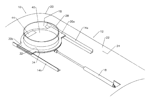
Referring to FIGURES 1 and 4, port closure 10 includes a
combination of a tank 12, a pair of guide tracks 14a and 14b,
a closure member in the form of a closure plate 16 and a
remotely controlled actuator preferably in the form of a
telescopically extendible cylinder 18. Tank 12 has defining
walls 20, an exterior surface 22, am interior surface 24, an
interior cavity 26 ~~nd an access port 28. One of the pair of
guide tracks 14a and 14b is mounted to the defining walls 20
on the interior surface 24 of the tank 12 on each of two
opposed sides of the access port 28.
Closure pa.ate 16 has a paur cf opposed track engaging
edges 30a and 3(7b. The track engaging edges 30a and 30b are
engaged with the pair of guide tracks 14a and 14b. Closure
plate 16 is movable along the guide tracks 14a and 14b between
a first positi<:~.:1 c7.osing the access. port ~8, illustrated in
FIGURES 1 through 3, and a second position laterally spaced
from the access port 28, illustivatec~ in FIGURES 4 through 6.
When a clo:;ure plate 16 is to be fitted into a new tank
12 closure plat_:e lE~ can be construe°ted frcm a single planar
sheet of material. When it is necessary to retrofit an
existing tank 12 without opening up raid tank 12 closure plate
CA 02245998 1998-08-26
6
16 is constructed inside tank 12 frorn more than one components
each of which i.s ca.pable of being passed through access port
28 as will now ke> described with reference tc> FIGURES 7 through
9.
Referring to FIGURES 7 and 8, closure plate 16 includes
a first layer 32 azd a second .Layer 34. First layer has a
first cut out portion 36 that permits first layer 32 to be
inserted througr. access port 28, as illustrated in FIGURES 9a
through 9f, but renders first layer .:.2 incapable of completely
covering the cz:~oss-sectional area o~ access port 28. Second
layer 34 has a :~eccnd cut out porti~~n 38 that permits second
layer 34 to be inserted through access port 28 in the same
manner as first layer 32 but renders second layer 34 incapable
of completely coverung the cross- sectional area of access port
28.
Referring to F:CGURE 7, first, la,,rer 32 and second layer 34
are secured in face to face relation to collectively form the
closure plate 1.E~ with an access porn engaging face 40 larger
than the cross-~;~ectional area of the access port 28. First
layer 32 and second layer 34 have interlocking members 42 and
44 respectively whi~~h, when interlocked, mare the access port
engaging face 4C. and the opposed face 46 of= closure plate 16
planar.
Referring to FIGURES 3 and 6, a seal zing 48 is mounted
to the defining wal~_s 20 on the interior surface 24 of tank 12
circumjacent t~i~=_ access port 28. Seal ring 48 sealingly
engages the accF~ss port engaging face 40 of closure plate 16
when closure p~'~~te 16 is in the first position closing the
access port 28 ~s illustrated in FIGURE 3.
Referring to FIGURES 1 through 6, a remotely controlled
actuator means such as telescopically extendible actuator
cylinder 18 is ~;~up7_ed with closure plate 16 to allow remotely
controlled movement. of closure plate 16. Cylinder 18 is
CA 02245998 1998-08-26
7
connected by fllzid lines to a remotely located fluid control
system (not shown) that controls the supply of fluid to
cylinder 18 to t~ale:~copically expand and contract cylinder 18,
thereby movinc:~ c7.osure 16 between the first position
illustrated in FIGURES 1 through 3 and the second position
illustrated in FIGURES 4 through 6.
The use and operation of port closure 10 will now be
described with reference to FIGURES 1 through 15c. In order
to retrofit an existing tank 12 with port closure 10, layers
32 and 34 are pas~.ed through acce"s port 28 in the manner
illustrated sequentially in FIGURES 9a through 9f. Then, first
layer 32 and second layer 34 are secured in face to face
relation by an a:~he~~ive to collectively form closure plate 16,
in the manner i Llu~;trated in FIGURE 7 . Closure plate 16 is
movable along guide tracks 14a and 14b between a first position
closing access port 28, as illustrated in FIGURES 1 through 3,
and a second position laterally spaced from access port 28, as
illustrated in FIGURES 4 through 6. c.'ylinder 18 telescopically
expands or contracts to move clc>surEe plate 16 from the first
position closing access port 28 to the second position
laterally spaced from access port 28. The movement of cylinder
18 is hydraulica ily or pneumatically ~Jontrolled from a remotely
located location, such as a cap of a transport vehicle or a
control room of a sl~orage facility. Should pressure increase
within tank 12, the pressure will farce access port engaging
face 40 of closure elate 16 into increased sealing engagement
with seal ring 48.
It will bE~ apparent to one ~kil.led in the art that
modifications may be made to the illu~~trated embodiment without
departing from the spirit and scope of the invention as
hereinafter defined in the Claims. Some modifications will now
be described with reference to FIGURES 10 through 15c.
Referring to FIGURES 10 through 12, there is illustrated a
first alternative form of closure member, generally identified
CA 02245998 1998-08-26
8
by reference numeral 116. Referring to FIGURE 12, Closure
member 116 has G primary component 118 with a cut out portion
120 that permits primary component 116 to be inserted through
an access port .in the same manner as illustrated in FIGURES 9a
through 9f. However, cut out portion 12o renders primary
component 118 incapable of covering the crc:~ss-sectional area
of the access port. Primary component 116 leas a plurality of
bolt receiving openings 122 positioned around a periphery of
cut out portion 120. A secondary component 124 is provided
which, when combined with primary component 116, fills cut out
portion 120. Seconc.ary component 124 has a flange 126 that has
a plurality of bolt _deceiving opening. 128. Secondary component
124 is secured to primary component 116 by a plurality of
threaded screws ~~r bolts 130 that extend through bolt receiving
openings 128 and 122. It will be apparent to one skilled in
the art that, if de~;ired, there cyan x~e more than one secondary
component 124. In. most installat-wons, only one secondary
component 124 w:i Ll be necessary. Ref~=rring to FIGURE 11, there
is illustrated tuhe manner in which bolts 130 are secured in
place by nuts 132. It is preferred for ease of handling that
secondary component 124 have an attachment member 134. The
reason for this is i~hat secondary component 124 is relatively
small and if a LinE~ is not secured to attachment member 134
there is a dan<:~er it could be accidentally dropped into the
tank. It is also preferred that: when primary component 116
consists of a ~~ingl.e plate, that reinforcing members 136 be
provided. In the embodiment illustrated in FIGURES 3 and 6, the
form of seal used i:~ a ring seal 48. Referring to FIGURES 10
and 12, there is il:Lustrated an alternative form of seal 138.
Seal 138 consists of a resilient :pealing layer secured by
adhesive to access port engaging face 140 of closure member
116.
Referring to FIGURES 13 and 14, there is illustrated a
second alternat ~~ ae form of closure member, generally identified
by reference numera_L 216. Closure m~amber 2~_6, as illustrated
consists of tw« i.nterlocking components 218 and 220. The
CA 02245998 1998-08-26
9
manner of intex:v_ock illustrated can be described as a tongue
in groove or ~~ male to fema_Le ~_nterlock. Interlocking
component 218 has a hale interlocking tongue 222. Interlocking
component 220 has a female interlocking groove 224. It would
be apparent to one skilled in t=he art that there are other
forms of interlock that would also x~e suitable.
Referring to FIGURES 15a through 15c, there is illustrated
a third altez:wnative form of closure member, generally
identified by tveference numeral 3:~6. Closure member 316
consists of twc components 318 and 320 whicro are coupled with
a hinge 322. When engaged in guide tracks 14a and 14b, closure
member 316 is ruaintained in a planar attitude as illustrated
in FIGURES 15a. FIGURES 15b and 15c illustrated how closure
member 316 can b=_ folded about hinge 322 for insertion through
an access openlr.g.
It will firl.~ll~.~ be apparent to one skilled in the art that
there are other modifications ma.y be made to the illustrated
embodiments without departing from the spirit and scope of the
invention as herein,~fter defined in the Claims.