Note: Descriptions are shown in the official language in which they were submitted.
CA 02246063 1998-08-28
ITW CASE 8205
RATCHETING CARGO LOAD BRACING BAR
FIELD OF THE l:NVENTION
The present invention relates generally to cargo
load bracing bars which are employed within cargo holds or
S spaces in order to restrain cargo loads against inadvertent or
undesirable movements during transportation of cargo loads,
and more particularly to a new and improved cargo load bracing
bar which can be operated in an easy and accurate manner when
disposed in its loading or extension mode by means of which
opposite ends of the cargo load bracing bar can frictionally
engage opposite walls of a cargo vehicle with a predetermined
amount of load or force so as to maintain the cargo load brac-
ing bar in its cargo load restraining position; which can be
easily disposed in a release mode by means of which the cargo
load bracing bar can either be rapidly longitudinally extended
to a length approximately corresponding to the distance defin-
ed between the cargo walls so as to then be ready for subse-
quent engagement with the cargo walls in accordance with the
aforenoted loading or extension mode, or alternatively, be
rapidly longitud.inally contracted so as to readily permit lon-
gitudinal collapse of the cargo load bracing bar so as to fa-
cilitate removal. of the cargo load bracing bar from the cargo
hold or space and permit storage of the cargo load bracing bar
in a compact marmer or subsequent use thereof in connection
with a subsequent cargo load bracing operation.
CA 02246063 1998-08-28
BACKG~OUND OF THE INVENTION
Cargo load bracing bars are of course we~l known and
widely employed within the transportation industry so as to
restrain movemenls of cargo loads during transportation of the
same. Such cargo load bracing bars conventionally comprise a
pair of telescoping tubular members wherein the distal ends of
the tubular members are provided with pad members fabricated
from a suitable elastomeric or other frictional material. When
the telescoping tubular rnembers are longitudinally extended
with respect to each other so as to engage opposite interior
wall surfaces of the cargo vehicle under predetermined load
conditions, the pad members frictionally engage such interior
wall surfaces of the cargo vehicle so as to retain the cargo
load bracing bar in the desired cargo restraining position
with respect to the cargo loads.
One t~e of well-known cargo load bracing bar uses a
ratchet mechanism to longitudinally extend or contract the
telescoping tubular members wherein the ratchet mechanism is
similar to that conventionally employed in connection with old
style automobile bumper jacks. As is well known, however, such
a ratchet mechanism can only longitudinally extend or contract
the tubular mem~,ers with respect to each other at a rate of
one tooth at a time whereby use of such bumper jacks has prov-
en to be quite t:edious, laborious, and time-consuming. In ad-
dition, use of such a ratchet mechanism and bumper jack alsorecluires the provision of an auxiliary lever which controls or
determines the clirection of operation of the jack, that is,
whether the jack is being longitudinally extended or contract-
ed. Operation OI- actuation of such an awciliary lever has
sometimes proven difficult, and sometimes, the lever has occa-
sionally malfunctioned.
Another type of cargo load bracing bar is disclosed
within United S~ates Patent 3,049,328 which was issued to
CA 02246063 1998-08-28
Bishop on August 14, 1962. The cargo load bracing bar disclos-
ed within this patent is seen to comprise an outer tubular
member 1, and an inner tubular telescoping mem~é,- 2, wherein
the free distal ends of the tubular members 1 and 2 are pro-
vided with frict:ional pads 3 for engaging the interior walls 4of a truck body.A rack 11, having a plurality of serially ar-
ranged teeth 13, is fixedly mounted upon the inner tubular
member 2 by means of a collar 8, and a handle 19 is pivotally
mounted upon the outer tubular member 1 by means of a sleeve
O mer~er 14. An end portion of the handle 19 is provided with a
hub or sector gear 22 comprising a plurality of teeth 23, for
example, four teeth, which are adapted to engage the teeth 13
of the rack ~1 so as to move the rack 11, and therefore the
inner tubular member 2, with respect to outer tubular member 1
when the handle 19 is moved from the position shown in FIGURE
4 to that shown in FIGURE 3. Collar 14 is provided with a
catch projection 27 and handle 19 is correspondingly provided
with a catch projection 24.
When lhe handle 19 is rotated from the position
shown in FIGURE 4 to that shown in FIGURE 3, the rack 11, and
therefore the inner tubular member 2, is moved relative to the
outer tubular member 1, and the newly extended position of the
inner tubular member 2, with respect to outer tubular member
1, is fixed and maintained as a result of the engagement of
the catch projection 24 of the handle 19 with the catch pro-
jection 27 of the collar 14 so as to prevent retrograde move-
ment of the rack 11, and therefore the inner tubular member 2,
with respect to outer tu~ular member 1. As can be readily ap-
preciated from l_he cargo load bracing bar systeIn of Bishop,
however, it is <,een that in view of the fact that the locking
or latching of the system only occurs when the handle 19 is
disposed in the position illustrated in FIGURE 3, an operative
extension stroke of the system necessarily comprises or en-
compasses a linear movement of the rack 11 and inner tubular
'35 member 2, with respect to outer tubular member 1, which cor-
CA 02246063 1998-08-28
responds to four serial teeth of rack 11. Consequently, it is
difficult to accurately or properly achieve a particularly de-
sired extension of the carg.o load bracing bar of Bishop so as
to exert a proper or predeterminedly desired load or force, by
means of its frictional pad members 3, upon the opposite in-
terior walls of the truck hody when, for example, a longitudi-
nal extension stroke merely comprises a limited distance cor-
responding to one or two serial teeth of rack 11.
Still another type of cargo load bracing ~ar system
is disclosed within United States Patent 5,443,342 which is-
sued to Huang on August 22, 1995. In accordance with this sys-
tem, a sleeve 21 is fixed to a tube 20, and a base 30 is
mounted upon the sleeve 21, the base 30 having a pivotable
handle 40 and a rotatable shaft 31 mounted thereon. A ratchet
gear 32 is fixed upon the shaft 31, and the handle 40 is pro-
vided with a catch 41 which is adapted to engage the ratchet
gear 32 so as to rotate the ratchet gear 32 when the handle 40
is moved in the clockwise direction as seen in FIGURES 1 and
3. The ratchet gear 32 is adapted to be engaged with the teeth
of a gear rack 10. A stop 33 is also mounted upon the base 30
so as to engage the teeth of the ratchet gear 32 in order to
prevent the ratchet gear 32 from rotating in the opposite di-
rection when the handle 40 is rotated in the counterclockwise
direction in preparation for a subsequent clockwise rotation
or operation in order to extend gear rack 10 further with re-
spect to tube 20.
Sleeve 21 is provided with a pair of ears 26 through
which a pivot pin 27 is disposed and by means of which the
base 30 is pivolally mounted upon the sleeve 21. Base 30 is
also provided with a pair of projections 35 through which a
pair of hooks 2:3, of a rod 22 molmted upon sleeve 21, are dis--
posed for cooperating with the pivot pin 27 in order to retain
the base 30 UpO]l sleeve 21. In order to disengage ratchet gear
32 from the gea:r rack 10 so as to permit gear rack 10 to free-
CA 02246063 1998-08-28
ly slide relative to the tube 20, the hooks 23 must be disen-
gaged from the projections 35 whereby the base 30 is then per-
mitte~ to rotate about the pivot pin 27. It can be readily ap-
preciated that with such a system, disengagement of the ratch-
et gear 32 from the gear rack 10 may be somewhat awkward anddifficult to achieve. In addition, it is also desirable to
move the actuating handle 40 to a collapsed position disposed
parallel to or atop, for example, tube 20 so as to render the
system compact once the cargo load bracing bar has been ex-
tended and fixed within the cargo space of the vehicle, aswell as for preventing the creation or presence of a potenti-
ally harmful or dangerous situation by means of the handle 40
projecting outwa.rdly or away fro~ the tube 20 as shown in
solid lines in F'IGURE 3 of the Huang patent, however, provi-
sion for such movement of the actuating handle 40 of Huang isnot provided.
A nee~1 therefore exists, in the art for a new and
improved cargo ]oad bracing bar which can be readily operated
in an easy, quick, and accurate manner in order to longitudi-
nally extend the bar to a predetermined length so as to im-
press necessary loads or forces upon the interior walls of a
cargo vehicle and thereby restrain and retain cargo loads
therein. In addition, it is desirable that the cargo load
bracing bar be ]eadily movable to a longitudinally collapsed
state for compactness and safety during cargo restraint or
storage ~odes, and to a released states for free movement
modes attendant preliminary extension of the cargo load brac-
ing bar prior to further extension of the cargo load bracing
bar for load or frictional engagement with the interior walls
of the cargo vehicle, or for longitudinal contraction of the
cargo load bracing bar for permitting removal of the cargo
load bracing bar from the cargo vehicle, and storage of the
contracted cargo load bracing bar, prior to its reuse in con-
nection with the restraint or retention of other cargo loads
within other cargo vehicles.
CA 02246063 1998-08-28
OBJECTS OF THE INrVENTION
Accordingly, it is an object of the present inven-
tion to provide a new and improved cargo load bracing bar.
Another object of the present invention is to pro-
vide a new and improved cargo load bracing bar which overcomesthe various defects, drawbacks, and disadvantages chracterist-
ic of prior art cargo load bracing bars.
A Eurt:her object of the present invention is to pro-
vide a new and improved cargo load bracing bar which can be
readily operated in an easy, quick, and accurate manner such
that the inner tube component, to which the gear rack is fix-
ed, can be longitudinally extended a lineal distance which is
e~ual to one or more gear teeth of the gear rack, and wherein
the cargo load bracing bar is also readily movable to collaps-
ed and released states so as to enhance compactness, safety,and rapid and easy longitudinal extension and contraction of
the cargo load bracing bar attendant preliminary use of the
cargo load bracing bar within a cargo vehicle in connection
with a cargo restraint operation, or removal of the cargo load
bracing bar from the cargo vehicle, and storage of the same,
upon completion of a cargo restraint operation.
SUMMARY OF THE INVENTION
The foregoing and other objects are achieved in ac-
cordance with the teachings of the present invention through
the provision oE a cargo load bracing bar assembly or system
which comprises inner and outer telescoping tubular members, a
housing fixedly secured to the outer tubular member, and an
elongated gear rack having one end thereof fixedly secured to
the inner tubular member so as to be movable with the inner
'30 tubular member when the same is telescopingly moved with re-
CA 02246063 1998-08-28
spect to the outer tubular member and an opposite end thereo~
freely disposed atop the outer tubular member so as to be
slidably movable along the outer tubular member. A pinion
gear, having gear teeth disposed thereon for engagement with
similar teeth of the gear rack, is rotatably mounted upon the
housing, as is an actuating ratchet handle. A spring-biased
ratchet is mount~ed upon the actuating ratchet handle so as to
be normally engaged with the pinion gear, and a spring-biased
pawl is confined between side wall portions of the housing and
is slidably disposed upon the gear rack such that a projecting
portion of the pawl is normally engaged with the pinion gear
so as to prevent rotation of the pinion gear in a direction
opposite that caused by the ratchet member.
When t:he actuating ratchet handle is moved in the
counterclockwise direction, the spring-biased ratchet member
is able to ratchet over one or more teeth of the pinion gear,
without rotating the pinion gear, in preparacion for causing
rotatable movement of the pinion gear which, in turn, will
cause predetermined lineal movement of the gear rack and the
inner tubular member with respect to the outer tubular member.
When the actuating ratchet handle is moved in the clockwise
direction, the ratchet causes clockwise rotation of the pinion
gear whereby a predetermined lineal extension of the gear
rack, and the inner tubular member, relative to the outer tub-
ular member is achieved. Upon completion of such rotatablemovement of the pinion gear, and the corresponding lineal
movement of the gear rack and the inner tubular member with
respect to the outer tubular member, the actuating ratchet
handle is again moved in the counterclockwise direction caus-
ing the ratchet member to again ratchet over one or more teethof the pinion gear in preparation for another operative cycle
by means of which the gear rack and the inner tubular member
can be moved a I?redetermined amount with respect to the outer
tubular member. It is noted that while the ratchet handle is
being moved in lhe counterclockwise direction, the spring-bi-
CA 02246063 1998-08-28
ased pawl mem~er engages one of the teeth of the pinion gear
so as to prevent rotation of the pinion gear in the counter-
clockwise direction thereby preventing retrograde movement of
the gear rack and contraction of the inner tubular member with
S respect to the outer tubular member.
In accordance with additionally unique features of
the cargo load bracing bar of the present invention, the
spring-biased ratchet member can be manually disengaged from
the pinion gear so as to permit the actuating ratchet handle
to be moved to a collapsed state wherein the actuating ratchet
handle is disposed above and parallel to the gear rack. This
serves to render the cargo load bracing bar relatively compact
and also eliminates a potential safety hazard in view of the
fact that the actuating ratchet handle would otherwise extend
in an angular mode outwardly away from the inner and outer
tubular me~bers. In addition, the actuating ratchet handle may
also be moved in the counterclockwise direction to a position
at which the ratchet member is disengaged from the pinion gear
and a head portion of the spring-biased ratchet member engages
the spring-biased pawl member so as to push the spring-biased
pawl member, against the biasing force of its associated
spring, out of engagement with the pinion gear. In view of the
fact that both t;he ratchet member and the pawl member are dis-
engaged from the pinion gear, the gear rack, and therefore the
inner tubular member operatively connected thereto, can be
freely moved wit;h respect to the outer tubular member whereby
the longitudina'L extension of the cargo load bracing bar can
be easily and rapidly adjusted to a length approximating the
interior expanse of the cargo hold or space of the cargo vehi-
cle in preparat:ion for subsequent accurate longitudinal exten-
sion of the cargo load bracing bar into frictional engagement
with the interior side walls of the cargo vehicle. In accord-
ance with an alternative operative mode, again, in view of the
fact that both the ratchet member and the pawl member are dis-
engaged from the pinion gear, the gear rack, and the inner
CA 02246063 1998-08-28
tubular member operatively connect,ed thereto, can be freely
moved in the oppc,site longitudinal direction relative to the
outer tubular me~er whereby the cargo load bracing bar can ~
easily and rapidl.y contracted so as to facilitate removal from
the cargo vehicle and storage of the cargo load bracing bar in
a compact state prior to its reuse in connection with a subse-
quent cargo load bracing operation.
BRIEF DESCRIPTION OF THE DRAWING~
Various other objects, features, and attendant ad-
vantages of the present invention will be more fully appreci-
ated from the fo:Llowing detailed description when considered
in connection wil_h the acco~panying drawings in which like
reference characters designate like or corresponding parts
throughout the several views, and wherein:
FIGURE 1 is a side elevational view of the new and
improved cargo load bracing bar constructed in accordance with
the principles and teachings of the present invention and il-
lustrated as being used within the cargo hold or space of a
cargo vehicle;
FIGURE' 2 is a partial, top plan view of the new and
improved cargo load bracing bar shown in FIGURE l; and
FIGURE~ 3 is a cross-sectional view of the cargo load
bracing bar shown in FIGURE 2 as taken along the lines 3-3 of
FIGURE' 2.
CA 02246063 1998-08-28
DETAILED DESCRIPTION OF THE PREFERRED EMBODIMENT
Referring now to the drawings,-~nd more particularly
to FIGURE 1 thereof, the new and improved cargo load bracing
bar constructed in accordance Wit}l the teachings and princi-
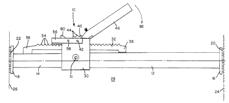
ples of the present invention is illustrated therein and isgenerally indicated by the reference character 10. The cargo
load bracing bar 10 is seen to comprise a first outer tubular
member 12, and a second inner tubular member 14 which is
adapted to be te:Lescopically movable within and with respect
to the outer tublllar member 12. The free oppositely disposed
ends of the outer and inner tubular members 12 and 14 are re-
spectively provided with pad members 16 and 18 which are in
turn provided with suitable elastomeric or frictional elements
20 and 22 for frictionally engaging interior wall surfaces 24
and 26 of a vehicle cargo hold or space 28 when the inner and
outer tubular me:mbers 12 and 14 are longitudinally extended
with respect to each other as will be more fully appreciated
hereinafter.
A housing 30 is fixedly attached to the outer tubu-
lar member 12 by means of a suitable bolt fastener or the like31, and a gear rack 32, having a plurality of serially arrang-
ed gear teeth 34, is fixedly secured at a first end 36 there-
of, by suitable means, not shown, to the inner tubular member
14 in such a manner that the gear rack 32 passes through the
housing 30 whereby a second opposite end 38 thereof is freely
slidable atop the outer tubular member 12. A pinion gear 40 is
rotatably mounted upon the housing 30 by means of another
suitable bolt fastener 42, and the pinion gear 40 is of course
provided with a plurality of gear teeth 44 disposed around its
outer periphery so as to be engageable or enmeshed with the
gear teeth 34 of the gear rack 32. An actuating ratchet handle
46 is also rotalably or pivotally mounted upon the housing 30
by means of the bolt fastener 42 such that the actuating
ratchet handle 46 is rotatable or pivotal about an axis which
. .
CA 02246063 1998-08-28
is coaxial with the rotatable axis of the pinion gear 40 as
defined by means of bolt fastener 42.
With reference now being additionally made to FIG-
I~RES 2 and 3, it is seen that the end of the actuating ratchet
5 handle 46 which is pivotally mounted upon the housing 30 by
means of the bolt fastener 42 actually comprises a clevis
structure which is defined by means of two axially spaced ears
48 and 50 between which the pinion gear 40 is disposed and re-
tained. In a similar manner, the housing 30 comprises a pair
10 of axially spaced, upstanding side walls 52 and 54 between
which the clevis structure of the actuati.ng ratchet handle 46
is disposed and retained as a result of the bolt fastener 42
passing through the housing side wall 52, the ear 48 of the
actuating ratchet handle 46, the pinion gear 40, the other ear
15 50 of the actuat.ing ratchet handle 46, and the other side wall
54 of the housir"g 30. A substantially L-shaped angle bracket
56, the purpose of which will be more fully appreciated here-
inafter, is secured to the exterior surface of housing side
wall 54 by means of bolt fastener 42 and another bolt fastener
20 58 wherein the ]atter fastener 58 likewise passes through the
upstanding housing side walls 52 and 54 as best illustrated in
FIGURE 2.
With reference now being additionally made specific-
ally to FIGURE :3, in order to operate the cargo load bracing
25 bar 10 in the desired modes, the cargo load bracing bar 10 is
seen to further comprise a ratchet member 60 which comprises a
substantially rectangular body structure 62 having a plate or
finger portion 54 projecting laterally outwardly from a side
portion of the body structure 62 such that the plate or finger
30 portion 64 is adapted to engage the teeth 44 of the pinion
gear 40. The body structure 62 of the ratchet member 60 is
provided with an internally threaded bore 66 within which the
lower end of a threaded screw or bolt fastener 68 is disposed
so as to mount the ratchet member 60 upon the actuating ratch-
~ . .
CA 02246063 1998-08-28
et handle 46. A ratchet spring 70 is disposed about the upper
end of the threaded screw or bolt fastener 68 so as to be in-
~.?rposed between an outer surface portion 72 of the actuating
ratchet handle 4G and a head portion 74 of the threaded screw
or bolt fastener 68. In this manner, the ratchet member 60 is
spring-biased in the upward direction whereby the plate or
finger portion 64 thereof is normally maintained engaged with
a tooth 44 of the pinion gear 40, and in addition, the ratchet
member 60 is able to be moved downwardly against the biasing
force of ratchet spring 70 for purposes which will be more
fully appreciated hereinafter.
On the other side of the rotational axis of pinion
gear 40, that is, on the side of the pinion gear 40 which is
opposite the side upon which the ratchet member 60 is dispos-
ed, there is disposed a pawl member 76 which comprises a flatplate portion 78 and an upstanding portion 80, wherein the
flat plate portion 78 is slidably disposed upon the upper sur-
face of the gear rack 32 and is slidably confined between the
upstanding side walls 52 and 54 of the housing 30 as best seen
in FIGURE 2. The angle bracket 56 is provided with a through-
bore 82 within which a peg or stud 84 is fixedly secured by
any suitable means. A coil spring 86 has one end thereof dis-
posed about the peg or stud 84 while the opposite end of the
spring 86 is disposed within a notched or recessed portion 88
defined within the upstanding portion 80 of the pawl member
76. In this mann.er, the pawl member 76 is spring-biased toward
the pinion gear 40 such that the right end of the flat plate
portion 78 of the pawl member 76, as viewed in FIGURE 3, is
normally engagec. or enmeshed with the pinion gear 40.
In operation, when the outer and inner tubular mem-
bers 12 and 14 of the cargo load bracing bar l0 are disposed
in a relatively extended position with respect to each other
such that the opposite ends thereof are disposed adjacent to
the side walls 24 and Z6 of the cargo vehicle and wherein it
12
CA 02246063 1998-08-28
is desired to fu:rther extend the outer and inner tubular mem-
bers 12 and 14 with respect to each other such that the fric-
tional elements :20 and 22 can engage the side walls 24 and 26
of the cargo vehicle with an increased amount of force and
thereby maintain the cargo load bracing bar 10 at a predeter-
mined position with respect to cargo loads to be restrained
thereby, the actuating ratchet handle 46 is pivoted or rotated
upwardly in the counterclockwise direction, as denoted by the
arrow 90, from its position shown in FIGURE 3 to that shown in
FIGURE 1.
As can be readily appreciated, in accordance with
such counterclockwise movement of the actuating ratchet handle
46, and in view of the spring-biased mounting of the ratchet
member 60 upon the actuating ratchet handle 46, the plate or
finger portion 64 of the ratchet member 60 is able to ratchet
over one or more teeth 44 of the pinion gear 40 depending upon
the angular extent to which the actuating ratchet handle 46 is
moved in the direction of arrow 90. At this time it is also
appreciated that; the pinion gear 40 is restrained or prevented
from undergoing any rotational movement in the counterclock-
wise direction in view of the enmeshed engagement of the flat
plate portion 7~3 of the pawl member 76 with the teeth 44 of
the pinion gear 40.
When the actuating ratchet handle 46 is then subse-
quently pivoted or rotated downwardly in the clockwise direc-
tion, as denoted by the arrow 92~ from the position shown in
FIGURE 1 to that shown in FIGURE 3, the plate or finger por-
tion 64 of the :ratchet member 60 will engage one of the teeth
44 of the pinion gear 40, depending again upon the angular ex-
tent to which t:he actuating ratchet handle 46 was initiallymoved in the counterclockwise direction 90, and as the actuat-
ing ratchet han~le 46 is moved downwardly and in the clockwise
direction 92, the plate or finger portion 64 of the ratchet
member 60 will cause angular rotation of the pinion gear 40 in
CA 02246063 1998-08-28
the clockwise direction which will, in turn, cause linear
movement of the gear rack 32 in the leftward direction as de-
noted by the arrow 94 so as to longitudinally extend the inner
tubular member 1~1 with respect to the outer tubular member 12.
It is to be noted in conjunction with the foregoing
operation that the clockwise rotation of the pinion gear 40 is
permitted and not prevented by means of the flat plate portion
78 of the pawl member 76 in view of the fact that as the pin-
ion gear 40 tends to rotate in the clockwise direction, the
teeth 44 of the ~pinion gear 40 which are serially engaged with
the flat plate portion 78 of the pawl member 76 will cause
slidable movement of the flat plate portion 78, and the pawl
member 76 itself, toward the left as viewed in FIGURE 3 and
against the biasing force of the coil spring 86. When a par-
ticular one of the teeth 44 of the pinion gear 40 then clearsthe flat plate portion 78 of the pawl member 76, the spring
biasing force of the coil spring 86 will move the pawl member
76 back toward the right as viewed in FIGURE 3 and thereby
cause the flat plate portion 78 of the pawl member 76 to
engage the next tooth 44 of the plinion gear 40.
If the pinion gear 40 continues to rotate in the
clockwise direction, then this cyclical engagement between the
pinion gear 40 and the pawl member 76 continues, however, if
there is no furt;her rotational movement of the pinion gear 40
in the clockwise direction as determined by means of the angu-
lar disposition of the ratchet member 60, then the pawl member
76 engages the pinion gear 40 so as to prevent rotational
movement of the pinion gear 40 in the counterclockwise direc-
tion and retrograde lineal movement of the gear rack 32 in the
contraction direction as denoted by the arrow 96. Repeated
cyclical movements of the actuat:ing ratchet handle 46 will re-
sult in repeate<1 lineal movements of the gear rack 32 and the
inner tubular member 14 relative to the outer tubular member
12 until the opposite ends of the cargo load bracing bar 10
14
CA 02246063 1998-08-28
are engaged with the interior wall surfaces 24 and 26 of the
cargo vehicle wilh a predetermine~ily desired degree of force.
As can thus be appreciated, the ratcheting system of
the present invention, as determined by the actuating ratchet
handle 46, the ratchet mernber 60, and the pinion gear 40, re-
sults in an easy and accurate lineal movement of the gear rack
32 and its operatively connected inner tubular member 14 which
may comprise a lineal distance equal to one gear tooth or sev-
eral gear teeth which is quitc di~ferent from the system of
Bishop as disclosed within United States Patent 3,049,328. In
accordance with the principles, teachings, and structure of
the cargo load bracing bar of the present invention, the pin-
ion gear 40 and the ratchet member 60 are related to each oth-
er such that one operative stroke of the actuating ratchet
handle 46 and the associated ratchet member 60 can cause ro-
tatable movement of the pinion gear 40, and a lineal movement
of the gear rack 32, through a distance equivalent to three or-
four gear teeth.
Another novel and unique feature of the present in-
vention resides in the fact that the actuating ratchet handle46 can be pivotally moved in the downward and clockwise direc-
tion from the position shown in E~IGURE 1 to the position shown
in FIGURE 3, even when rotation of the pinion gear 40 in the
clockwise direct;ion 92 and lineal movement of the gear rack 32
in the extended direction 94 can no longer be readily achieved
in view of the i-act that, for example, the outer and inner
tubular members 12 and 14 are already longitudinally extended
to their maximum extent with respect to each other whereby the
elements 20 and 22 are tightly and frictionally engaged with
the side walls 24 and 26 of the cargo vehicle, and in the in-
stance that the actuating ratchet handle 46 is disposed at an
angular orientation or position which is similar to that shown
in FIGURE 1. For compactness and safety purposes, however, it
is desirable th~t upon completion of an installation operation
lS
CA 02246063 1998-08-28
of a cargo load bracing bar, as shown in FIGURE 1, the actuat-
ing ratclhet iland:Le 46 be disposed at an angular orientation or
position which is as illustrated :Ln FIGURE 3 whereby the ~ctu-
ating ratchet handle 46 will be disposed substantially paral-
5 lel to and atop l he gear rack 32.
In order to achieve this disposition of the actuat-
ing ratchet handle 46, that is, in order to move the actuating
ratchet handle 46 from its position illustrated in FIGURE 1 to
that showr, in FIIJURE 3, without causing any rotation of the
10 pinion gear 40 a:nd any consequent lineal movement of the gear
rack 32 and its associated tubular member 14, a manual force
is simply exerted upon the head portion 74 of the screw or
bolt fastener 68 of the ratchet member 60 so as to in effect
move the ratchet member 60 downwardly against the upward bias-
15 ing force of the ratchet spring 70 whereby the plate or fingerportion 64 of the ratchet member 60 is disengaged from its
normally engaged disposition with respect to the pinion gear
40. Consequently, while the screw or bolt fastener 68 of the
ratchet member 60 is maintained depressed so as to maintain
20 the plate or finger portion 64 of the ratchet member 60 in its
disengaged state with respect to the pinion gear 40, the actu-
ating ratchet handle 46 can be rotated or pivoted in the
clockwise direct;ion 92 to the position shown in FIGURE 3. Upon
attaining such position, pressure upon the head portion 74 of
25 the screw or bo] t fastener 68 may then be removed whereby the
ratchet spring 7 0 will again bias the ratchet member 60 up-
wardly such that, the plate or finger portion 64 will again
engage the pinion gear 40.
A last novel and unique feature characteristic of
30 the present invention resides in the fact that the cargo load
bracing bar 10 ~_an be rapidly and easily longitudinally ex-
tended and cont:racted. This mode of operation is achieved as a
result of both the plate or finger portion 64 of the ratchet
member 60 and the flat plate portion 78 of the pawl member 76
16
CA 02246063 1998-08-28
being simply and easily simultaneously disengaged from their
respective engaged states with the pinion gear 40 so as to
permit the pinion gear 40, and th-reCore the gear rack 32 and
its associated t~lbular member 14, to respectively freely and
rapidly rotate, and move longitudinally, such that the inner
tubular member 14 can be rapidly moved longitudinally in both
the extension and contraction directions with respect to the
outer tubular me:mber 12.
Rapid longitudinal extension of the cargo load brac
ing bar 10, that is, the rapid longitudinal extension of the
inner tubular member 14 with respect to the outer tubular mem-
ber 12, is desired when the cargo load bracing bar 10 is ini-
tially being used within a particular cargo hold or space 28
so as to preliminarily extend the cargo load bracing bar 10 to
a length which approximates the distance defined between the
opposite side walls 24 and 26 of the cargo hold or space 28.
Once such preliminary extension of the cargo load bracing bar
10 has been achieved, the inner tubular member 14 of the cargo
load bracing bar 10 may then be incrementally extended with
respect to the outer tubular member 12 of the cargo load brac-
ing bar 10 in accordance with the aforenoted ratcheting opera-
tions achieved by means of the pinion gear 40, the gear rack
32, the ratchet member 60, and the pawl member 76. In an al-
ternative mode of operation, rapid longitudinal contraction of
2S the cargo load bracing bar 10, that is, the rapid longitudinal
contraction of lhe inner tubular member 14 with respect to the
outer tubular member 12, is desired when, for example, a par-
ticular cargo load transportation operation has been completed
and the cargo load bracing bar 10 is to be removed from the
cargo hold or s]?ace 28 so that the cargo load bracing bar 10
may be stored o:r readied for a subsequent cargo load bracing
operation within a different cargo hold or space 28.
In order to disengage both the plate or finger por--
tion 64 of the ratchet member 60 and the plate portion 78 of
CA 02246063 1998-08-28
the pawl member '76 from the pinion gear 40 so as to permit the
pinion gear 40 to freely rotate and the gear rack 32 to under
go free longi' u~inal movement so as to achieve, in turn, such
rapid longitudinal extension and contraction of the inner tub-
5 ular member 14 with respect to the outer tubular member 12,the actuating ratchet handle 46 is rotated or pivoted in the
counterclockwise direction 90. This movement of the actuating
ratchet handle 46 can be achieved either by simply moving the
actuating ratchet handle 46 in the counterclockwise direction
10 90 and permitting the flat plate or finger portion 64 of the
ratchet member 60 to ratchet over the several teeth 44 of the
pinion gear 40 until the flat plate or finger portion 64 of
the ratchet mem~er 60 clears pinion gear 40, or alternatively,
a downward force may again be applied to the head portion 74
15 of the ratchet screw or bolt fastener 68 so as to initially
disengage the flat plate or finger portion 64 of the ratchet
member 60 from t;he gear teeth 44 of the pinion gear 40.
In either case, once the actuating ratchet handle 46
has been rotatecl or pivoted to an angular position at which
20 the flat plate or finger portion 64 of the ratchet member 60
is entirely clear of the gear teeth 44 of the pinion gear 40,
rotation or pivoting of the actuating ratchet handle 46 is
continued until the head portion 74 of the ratchet screw or
bolt fastener 68 encounters an inclined or slanted surface
25 portion 98 of the upstanding member or portion 80 of the pawl
member 76, such movement of the head portion 74 of the ratchet
screw or bolt fastener 68 being denoted by means of the arrow
100. As a result of the head portion 74 of the ratchet screw
or bolt fastener 68 forcefully encountering the slanted or in-
30 clined surface portion 98 of the upstanding member or portion80 of the pawl ~member 76, the pawl member 76 will be force-
fully moved toward the left against the biasing force of the
pawl spring 86 whereby the flat plate portion 78 of the pawl
member 76 will be disengaged from the pinion gear 40. There-
35 fore, in view of the fact that both the plate or finger por-
18
CA 02246063 1998-08-28
tion 64 of the ratchet member 60 clnd the flat plate portion 78
of the pawl member 76 have been ei~fectively disengaged from
the teeth 44 of the pinion gear 4(), the pinion gear 40 is per-
mitted to freely rotate whereby the gear rack 32 and its ope-
ratively associated inner tubular member 14 are able to berapidly freely extended or contracted as desired so as to
achieve the aforenoted operational states attendant use of the
cargo load bracing bar 10.
Thus it may be seen that in accordance with the
principles and teachings of the present invention, a new and
improved cargo load bracing bar has been developed whereby ex-
tension of the inner tubular member with respect to the outer
tubular member can be easily and accurately achieved in incre-
ments of a single tooth or multiple teeth depending upon the
angular extent to which the actuating ratchet handle, and the
ratchet member carried thereby, is moved or positioned with
respect to the pinion gear. In addition, the actuating ratchet
handle may be mc~ved to a collapsed state so as to render the
same compact as well as to eliminate any potential safety haz-
ards, and still further, the actuating ratchet handle may bemoved to a relea,se state or position at which the ratchet and
pawl members are effectively disengaged from the pinion gear
so as to permit the pinion gear to freely rotate whereby the
gear rack can be freely moved longitudinally so as to permit
the cargo load bracing bar to be rapidly extended or contract-
ed as a result of the inner tubular member being rapidly ex-
tended or contracted with respect to the outer tubular member.
Obviously, many modifications and variations of the
present invention are possible in light of the above teach-
ings. It is the~efore to be understood that within the scopeof the appended claims, the present invention may be practiced
otherwise than as specifically described herein.
19