Language selection

Search

Patent 2246402 Summary

Third-party information liability

Some of the information on this Web page has been provided by external sources. The Government of Canada is not responsible for the accuracy, reliability or currency of the information supplied by external sources. Users wishing to rely upon this information should consult directly with the source of the information. Content provided by external sources is not subject to official languages, privacy and accessibility requirements.

Claims and Abstract availability

Any discrepancies in the text and image of the Claims and Abstract are due to differing posting times. Text of the Claims and Abstract are posted:

  • At the time the application is open to public inspection;
  • At the time of issue of the patent (grant).
(12) Patent: (11) CA 2246402
(54) English Title: DOOR/SILL INTERFACE FOR A WAREWASHER
(54) French Title: JOINT D'ETANCHEITE POUR BAS DE PORTE DE LAVE-VAISSELLE
Status: Deemed expired
Bibliographic Data
(51) International Patent Classification (IPC):
  • A47L 15/42 (2006.01)
  • A47L 15/24 (2006.01)
(72) Inventors :
  • HECKER, DEAN A. (United States of America)
  • DEBROSSE, WALTER L. (United States of America)
(73) Owners :
  • PREMARK FEG L.L.C. (United States of America)
(71) Applicants :
  • PREMARK FEG L.L.C. (United States of America)
(74) Agent: GOWLING WLG (CANADA) LLP
(74) Associate agent:
(45) Issued: 2001-02-06
(22) Filed Date: 1998-09-02
(41) Open to Public Inspection: 1999-03-05
Examination requested: 1999-09-29
Availability of licence: N/A
(25) Language of filing: English

Patent Cooperation Treaty (PCT): No

(30) Application Priority Data:
Application No. Country/Territory Date
60/058,089 United States of America 1997-09-05

Abstracts

English Abstract


A joint for forming a seal between a warewasher
and the bottom of a generally rectangular, vertically
movable door housed in the warewasher to inhibit release of
moisture into the ambient atmosphere. The door has an outer
face and is shaped to cover a generally rectangular opening
in the warewasher. The joint includes a sill located along
the bottom edge of the opening having a downwardly angled
surface to retain moisture in the warewasher and an upper
assembly located along the lower edge of the outer face
including a handle shaped to mate with the sill. The upper
assembly further includes a downwardly extending saddle
shaped to cover the interface between the handle and the
sill to facilitate the retention of moisture in the
warewasher.


French Abstract

Cette invention concerne un joint d'étanchéité pour bas de porte de lave-vaisselle conçu pour empêcher l'humidité d'envahir l'air ambiant. La porte de l'appareil, de forme rectangulaire, s'ouvre verticalement. Le joint est constitué d'un élément inférieur posé au bas de l'ouverture et présentant une surface inclinée de manière à retourner l'humidité à l'intérieur de l'appareil, d'un élément supérieur posé au bas de la face extérieure de la porte et comportant une poignée de forme correspondant à celle de l'élément inférieur, et d'un élément intermédiaire également incliné et formé de manière à servir d'interface entre l'élément supérieur et l'élément inférieur pour s'opposer au passage de l'humidité.

Claims

Note: Claims are shown in the official language in which they were submitted.

CLAIMS

1. An elongated conveyor warewasher comprising:
an outer housing;
a chamber formed in said housing through which ware may
pass;
a generally rectangular access opening formed in said
housing which opens into said chamber;
a sill located along the bottom edge of said opening,
said sill having a downwardly angled surface to inhibit the
release of moisture through said opening from said chamber;
a generally rectangular, vertically movable door
shaped and positioned to cover said access opening when said
door is closed, said door having an outer face and a lower
edge; and
an upper assembly located along the lower edge of said
outer face, said upper assembly including a handle shaped to
mate with said sill thereby forming a seal between said sill
and said handle, and a downwardly extending saddle shaped to
cover the interface between said handle and said sill when
said door is closed.

2. The warewasher of claim 1 wherein said sill and
said upper assembly are made of steel.

3. The warewasher of claim 2 wherein said door
includes a notch at its lower edge, said upper assembly
being mounted in said notch.

4. The warewasher of claim 3 wherein said upper
assembly is mounted to said door by threaded fasteners
passing through said upper assembly and into said door


5. The warewasher of claim 4 further comprising a
pair of flanges mounted to the sides of said door, said
flanges being received in cooperating slots formed in said
housing to thereby guide the vertical movement of said door.

6. The joint of claim 5 wherein said handle includes
a grip portion which provides a convenient surface for
gripping said door.


Description

Note: Descriptions are shown in the official language in which they were submitted.


CA 02246402 1998-09-02

Docket ~o. 006593-1696
PAT ~ T

DOO~/SILL I~n~E ~ ACE FOR A WA~U~N ~ ~ R

CROSS REF~E~F TO RELATED ~PPT~ICATIONS

This application claim~ priority under 35 U.S.C.
ll9 from provisional application Serial No. 60/058,0~9 ~iled
Septe~ber 5 1991, the entixe disclosure of which is
incorporated herein by reference.

BACK~ROuND

The present invention relates to a warewasher
having an acce~ door ~hat ~buts against a lower ~ill o~ the
warewasher, the door and the sill being shaped to inhibit
moisture from escaping ~rom the warewasher when the door is
closed against the sill.

BACKGROU~3 OF l~iF IN~ TION

Commercial conveyer-type warewashers ~ypicall~
include a long, rectangular chamber through which the ware
tra~els, and an endless conveyor which transports the ware
through the chamber. The washer may include a serie~ of
stations within the inner chamber to effect different stages
of the wa~hing process. Exa~ples of the~e stages include
the pre-ri~se, wash, rinse, dry as well as other cycles
whlch are carried out at different locations in the
- warewasher as the ware i~ transported along the conveyor
In warewashers of thi~ type, it is often de~ired to allow
the operator acce~s to the inner chamber to detect and
correct jam~, observe the cleanliness of the ware, as well

CA 02246402 1998-09-02

Docket ~o. 006593-l696
as inspect, ser~ice, and maintain various components of the
warewasher.

Accordingly, ~ccess to the ~axewasher is typically
provided by a geries o~ large, rectangular doors located on
the sides of the washer. The doors are typically mo~eable
in the vertical direction to o~fer access to the inner
chamber and include a seal around the periphery of the door
to secure steam and water in the warewasher chamber when the
door is in the closed po~ition. Warewashers use a large
~olume of agitated, ho~ water, and therefore it i-~
imperati~e that the access doors form an e~fective seal with
the warewasher to retain heat and moisture in the ~sher~
Furthermore, due to the dem~c attendant with co~ercial
use, ~he sealing mechanism must be capable of withstanding
prolonged exposure to hea~ and mo~sture enclosed by the
warewasher. Accordingl~, there exists a ~eed for a
door/warewashe~ interface which forms an effective seal,
which can withstand the harsh en~ironment of a warewasher,
and which inhi~i~s ~he release of steam and m~i~ture from
the cnamber to the ambien~ environment

SUMMARY QF T~E INV$NT~ON

The presen~ invention is a warewasher having a
joint for forming a seal between the warewasher and the
bottom of a generally rectangular, ~ertically moveable door
housed in the warewasher. The seal of the present i~vention
effecti~ely retains heat and moisture within the war~washer
and effecti~ely resists corrosion, even when ex~osed to
repeated cycles o~ the warewasher

CA 02246402 1998-09-02
Doc3cet No. 006593-1696
More particularly, the present invention provides
a 7 oint for forming a ~aeal between a warewa~her and the
botto~n of a generally rectangular, vertically movable door
housed in the warewasher. The door has an outer face and is
shaped to cover a generally rectangular openi~g in the
warewasher. The joint compri~es a sill located along the
bottom edge of the opening, the sill having a downwardly
angled sur~ace to help direct any escaping moisture back
into the warewasher. The joint further comprise~ an upper
assembly located along the lower edge of the outer face of
the warewasher. The upper assembly includes a handle shaped
so as to ~ate with the sill, and a downwardly extending
saddle shaped to cover the interfa~e between the ha~dle and
the sill to retain ~oisture in the warewa~her. Using this
arrangement, moisture is inhibited from escaping from the
warewasher.

These and other objeccs and advantages of the
present invention will be more fully unders~ood and
appreciated by reference to the following description, the
accompanying drawings and the appended clai~s.

E~RIEF DESCRI ~l~ION OF THE DRaWINGS

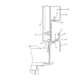
Fig. 1 is a side ele~ational view of the door/sil7
interface ~or a warewasher of the present invention;
Fig. 2 is a front elerat~onal view of the door of
the present invention;
~ ig 3 is a bottom plan view of the door of Fig.
2;
Fig. 4 iS a side elevational view o~ the door of
Fig 2;

CA 02246402 1998-09-02
Docket ~o. 0065~3-1696
Fig. 5 is a front plan view of the sill of the
present inventioni
Fig. 6 is a top plan view of the sill of Fig. 5;
Fig. 7 iS an end ele~ational view of the sill of
~ig. S; and
Fig. 8 i~ a perspective ~iew of the joint o~ ~ig.
1.

DETAIl.l;:D DESCRIPTIO~J

The present invention is preferably employed in an
o elongated conveyor warewasher which is used for washing,
sanitizing and rinsing ware. As shown in Fig. 8, ~
warewasher 36 ~or use with the doorJ~ill interface of the
present invention includes an outer housing 30 and a
longit--~; nAl ly-orien~ed chamber 32 formed in the housing 30
through which the ware pas~es. A generally rec~angular
access ope~ing 34 is formed in the hou~ing 30 to provide
acces~ into the cham~er 32 A door 16 is pro~ided for
sealing the chamber 32 from the ambient atmo~phere during
operation of the warewasher 36. ~ handle 14 is positioned
2~ on the bottom of the door 16 to facilitate access ~o the
chamber 32 and is shaped to mate wi~h a sill l~ positioned
on the lower portion of the housing 30 ~elo~ the access
opening 34.

As shown best in ~ig. 1, a joint lO is formed at
the inter~ace be~ween the sill 12 and the handle 14. The
handle 14 is rigidly connected to the door 16 by a series o~
- t~readed ~asteners 18. The handle 14 includes a downwardl~
angled surface 15 which mates ~ith a corresponding
downwardly angled surface 13 on the sill 12. Handle 14
includes grip portion 17, which provides a convenient


CA 02246402 1998-09-02
Docket No. 006593-1696
surface ~or a user to grip when clo~ing or opening the door
16 to gain access to the chamber 32

Door 16 has an outer face 22 which is exposed to
the a~bient atmosphere and an inner face 24 whi~h is exposed
to the interior of the warewasher 3~. The door 16 includes
an upper assembly 26 made up of a saddle 20, which extends
downwardly into the chamber 32, and the handle 1~. The
saddle 20 is shaped to extend below the joint 10 when ~he
door 16 ls in the closed position, thereby inhibiting the
0 release of moi3ture from the chamber 32 to the ambient
atmosp~ere. The upper assembly 26 is attached along the
lower edge 27 o~ the door 16, and is preferably formed ~rom
~teel. As ~hown in Figs. 2, 3 and 4 ,the door 1~ is notched
21 along its lower edge to provide a surface for mounting
the upper assembly 26

The sill 12, as shown ~est in ~igs. 1, 5, 6 and 7,
ha~ a downwardly angled surface 13 which is shaped to mate
with the downwardly ~ngled surface 15 of t~e handle 14 in
2 0 order to retain moistu~e in ~he warewasher. During
operation of the warewasher 36, it is common for ~oisture
escaping from the chamber 32 to condense on the surface 13
of the sill 12. In prior ar~ warewashers, this conden~ation
had a tendency to ~e blo~n into the ambient atmosphere,
thereby decreasing the efficiency of the warewasher and
genexally making a mess in the surrounding work area.
However, d~e to the downwardly angled surface 13 of the
sill 12, in the present invention this condensation has a
tendency to flow down~ard, by ~orce of gravit~, back into
the warewasher.

CA 02246402 1998-09-02
Dockes No. 006593-16g6
As shown in Fig. 1, when the door 16 is in the
closed position, the handle 14 mates ~ith the sill 12 to
form an effecti~e seal 1~. To ~urther aid in retainin~
~oisture and heat, the saddle 20 co~ers the joint lO.
As ~hown bes~ in Fig. 3, ~he door 16 preferabl~ includes a
pair of outwa~dly-extending flan~es 40 along its sides. The
flanges 40 fit within guide slots (not shown) formed in ~he
~ousing along the cide of the access opening 34 to guide the
vertical movemen~ o~ the ~oor 16.

While the forms of apparatus herein de~cri~ed
co~sti~ute z pre~erred e~bodiment of the in~ention, it is to
be understood that the p~e~ent in~ention is not limuted to
these preci~e ~orms and that c~anges may be made therein
without departing from She scope of the in~ention.

What is claimed is:

Representative Drawing
A single figure which represents the drawing illustrating the invention.
Administrative Status

For a clearer understanding of the status of the application/patent presented on this page, the site Disclaimer , as well as the definitions for Patent , Administrative Status , Maintenance Fee  and Payment History  should be consulted.

Administrative Status

Title Date
Forecasted Issue Date 2001-02-06
(22) Filed 1998-09-02
(41) Open to Public Inspection 1999-03-05
Examination Requested 1999-09-29
(45) Issued 2001-02-06
Deemed Expired 2009-09-02

Abandonment History

There is no abandonment history.

Payment History

Fee Type Anniversary Year Due Date Amount Paid Paid Date
Registration of a document - section 124 $100.00 1998-09-02
Application Fee $300.00 1998-09-02
Request for Examination $400.00 1999-09-29
Maintenance Fee - Application - New Act 2 2000-09-04 $100.00 2000-08-15
Final Fee $300.00 2000-10-26
Maintenance Fee - Patent - New Act 3 2001-09-04 $300.00 2001-11-01
Maintenance Fee - Patent - New Act 4 2002-09-03 $100.00 2002-08-20
Maintenance Fee - Patent - New Act 5 2003-09-02 $150.00 2003-08-21
Maintenance Fee - Patent - New Act 6 2004-09-02 $200.00 2004-08-20
Maintenance Fee - Patent - New Act 7 2005-09-02 $200.00 2005-08-19
Maintenance Fee - Patent - New Act 8 2006-09-05 $200.00 2006-08-17
Maintenance Fee - Patent - New Act 9 2007-09-04 $200.00 2007-08-17
Owners on Record

Note: Records showing the ownership history in alphabetical order.

Current Owners on Record
PREMARK FEG L.L.C.
Past Owners on Record
DEBROSSE, WALTER L.
HECKER, DEAN A.
Past Owners that do not appear in the "Owners on Record" listing will appear in other documentation within the application.
Documents

To view selected files, please enter reCAPTCHA code :


To view images, click a link in the Document Description column. To download the documents, select one or more checkboxes in the first column and then click the "Download Selected in PDF format (Zip Archive)" or the "Download Selected as Single PDF" button.

List of published and non-published patent-specific documents on the CPD .

If you have any difficulty accessing content, you can call the Client Service Centre at 1-866-997-1936 or send them an e-mail at CIPO Client Service Centre.


Document
Description 
Date
(yyyy-mm-dd) 
Number of pages   Size of Image (KB) 
Representative Drawing 1999-03-23 1 6
Cover Page 2001-01-05 1 46
Abstract 1998-09-02 1 24
Representative Drawing 2001-01-05 1 6
Cover Page 1999-03-23 1 46
Description 1998-09-02 6 222
Claims 1998-09-02 2 48
Drawings 1998-09-02 5 58
Prosecution-Amendment 1999-09-29 1 31
Prosecution-Amendment 2000-02-08 2 86
Correspondence 2000-10-26 1 29
Assignment 1998-09-02 4 173