Note: Descriptions are shown in the official language in which they were submitted.
CA 02246447 1998-08-12
WO 97/32723 PCT/US96/11867
METHOD FOR MAKING A MULTILAYER POLYESTER FILM HAVING
A LOW COEFFICIENT OF FRICTION
w
FIELD OF THE INVENTION
The present invention relates to multilayer films, and in particular to
multilayer films comprising a plurality of layers of naphthalene dicarboxylic
acid
polyester and terephthalic acid polyester.
BACKGROUND OF THE INVENTION
Polyester films of various compositions are known to the art. These films,
which may be continuously extruded into sheets of various thicknesses, have
good
tensile strength and modulus, and have found use, among other things, as
magnetic
media substrates.
To date, much attention in the art has been focused on the optical properties
of multilayer films. Alfrey et al., Polymer Engineering and Science, Vol. 9,
No. 6,
pp. 400-404 (November 1969), Radford et al., Polymer Enaineering and Science,
Vol. 13, No. 3, pp. 216-221 (May 1973), and U.S. 3,610,729 (Rogers), for
example, describe the reflectivity of certain multilayer polymeric films. This
work
has been extended to multilayer polyester films. Thus, U.S. 3,801,429 (Schrenk
et
al.) and U.S. 3,565,985 (Schrenk et al.) disclose multilayer composites made
from
various resins, including polyesters, and methods for making the same. The
composites have the property of being iridescent, even without the addition of
pigments.
U.S. 4,310,584 (Cooper et al.) describe the use of polyesters in making
multilayer iridescent light-reflecting film. The film includes alternating
layers of a
high refractive index polymer and a polymer with a low refractive index. The
high
refractive index polymer is a cast nonoriented film that includes a
thermoplastic
polyester or copolyester such as polyethylene terephthalate (PET),
polybutylene
terephthalate and various thermoplastic copolyesters which are synthesized
using
more than one glycol and/or more than one dibasic acid.
CA 02246447 1998-08-12
WO 97/32723 PCT/US96/11867
U.S. 5,122,905 (Wheatley) describes a multilayer reflective film with first
and second diverse polymeric materials in alternating layers that exhibits at
least
30% reflection of incident light. The individual layers have an optical
thickness of
at least 0.45 micrometers, and adjacent layers have a refractive index
difference of
at least 0.03. U.S. 5,122,906 (Wheatley) describes similar reflecting bodies,
wherein a substantial majority of individual layers have an optical thickness
of not
more than 0.09 micrometers or not less than 0.45 micrometers, and adjacent
layers
have a refractive index of at least 0.03.
Some attempts have also been made to improve the mechanical properties of
particular multilayer films. Thus, U.S. 5,077,121 (Harrison et al.) describes
polyethylene-based multilayer films consisting of layers of two or more
different
resins, wherein the draw ratios of the composite film are found to exceed the
draw
ratios of monolithic films of the component materials. In the films described,
a layer
of high elongation, low modulus material is sandwiched between layers of low
elongation, low modulus material. The reference also notes that a similar
phenomenon is sometimes observed in composites wherein a high modulus, low
elongation material is sandwiched between layers of high elongation material,
although in many of these composites, the low elongation material fails at its
characteristic low elongation, causing a simultaneous, premature failure of
the high
elongation layers.
To date, however, relatively few improvements have been made in the
mechanical properties of multilayer polyester films, despite the fact that
such films
have become increasingly important in a wide variety of commercial
applications.
While polyester films are already available which have a high modulus and
medium
elongation, in a variety of uses, as when polyester films are used as
engineering
materials or are subject to winding operations, the physical limitations of
these films
are already being tested. There thus remains a need in the art for a
multilayer
polyester film having improved mechanical properties, and for a method of
making
the same. In particular, there is a need in the art for multilayer polyester
films
having improved tensile modulus, tensile strength, and stretchability.
2
CA 02246447 1998-08-12
WO 97/32723 PCT/US96/11867
A further problem encountered with polyester films, and frequently
commented on in the literature, relates to the incidence of hazing. Hazing in
polyester films is undesirable in applications where a clear film would be
preferred,
as in window films. In other applications, a particular degree of hazing is
acceptable or even desirable. To date, however, the phenomenon of hazing has
been poorly understood, and no methods have been provided which allow for easy
control of the degree of hazing in polyester films. There is thus a need in
the art for
a method of controlling t-he degree of hazing in polyester films, and
particularly in
multilayer polyester films. In particular, there is a need in the art for a
method of
producing multilayer polyester films with any desired degree of hazing,
through
manipulation of readily controllable process parameters.
Yet another problem encountered in polyester films relates to their
coefficient of friction. Thin polyester films having a high coefficient of
friction are
prone to wrinkling, web breaks, and similar damage during winding and
handling.
In these applications, it would be desirable to use a polyester film having a
lower
coefficient of friction, so that adjacent surfaces of the film would slide
over each
other easily.
To date, this has been accomplished through the use of slip agents.
However, the use of slip agents is undesirable in that it complicates the
manufacturing process, and frequently compromises the mechanical or optical
properties of the resulting film. There is thus a need in the art for
polyester films
which are substantially devoid of slip agents, but which have a comparatively
low
coefficient of friction. There is also a need in the art for a method of
controlling the
coefficient of friction in a polyester film without the addition of slip
agents.
These and other needs are met by the present invention, as hereinafter
disclosed.
SUMMARY OF THE INVENTION
In one aspect, the present invention relates to a new class of polyester
multilayer films, and to a method for making the same. Surprisingly, it has
been
found that, by extruding a film having alternating layers of polyethylene
naphthalate
3
CA 02246447 2006-04-11
60557-5897
(PEN) and polyethylene terepthalate (PET), a multilaver composite is obtained
which can be stretched to a higher draw ratio than monolithic films of
comparable
dimensions of either PEN or PET. Upon orientation, the multilayer film has a
tensile modulus and tensile strength superior to that of monolithic films of
PEN or
PET. The composite structure permits the PET layers within the film to remain
stretchable even after they have crystallized. Remarkably, the optimum
stretching
temperature for these films is found to be significantly higher than the glass
transition temperature of either component resin. By contrast, the optimum
stretching temperature for monolithic films of each component resin are known
in
the art to be only slightly above Tg.
In another aspect, the present invention relates to a method by which
multilayer polyester films having a desired degree of hazing may be produced
in a
continuous or noncontinuous manner, at various combinations of intrinsic
viscosities and at various ratios of PEN to PET, and with either PET or PEN as
the
surface resin. Surprisingly, it has been found that the degree of haze in the
finished
stretched film can be controlled through proper manipulation of preheating
temperature and duration. Thus, the method allows films to be produced with
any
desired degree of clarity. Various other features of the films, including
shrinkage,
friction, color, and modulus, may also be controlled through manipulation of
these
and other parameters.
In yet another aspect, the present invention relates to polyester films having
a desired degree of surface roughness, and to a method for making the same.
Surprisingly, it has been found that the degree of crystallization of PET in a
multilayer film comprising layers of PET and PEN can be used to manipulate the
degree of surface roughness so as to provide a polyester film that has a
slippery
surface without the addition of slip agents.
4
CA 02246447 2006-04-11
60557-5897
According to one aspect of the present invention,
there is provided a method for imparting a slippery surface
to a film, comprising the steps of: providing a film having
a surface layer and a second layer, wherein the surface
layer comprises a naphthalene dicarboxylic acid polyester,
and further wherein the second layer comprises a
terephthalic acid polyester; and heating the film for a
sufficient time, and at a sufficient temperature, until the
second layer has substantially crystallized; characterized
in that the second layer is in sufficient proximity to the
surface layer to substantially disrupt the smoothness of the
surface.
BRIEF DESCRIPTION OF THE DRAWINGS
FIG. la is a schematic drawing of a first
embodiment of the multilayer film of the present invention;
4a
CA 02246447 1998-08-12
WO 97/32723 PCT1US96/11867
FIG. lb is a schematic drawing of a second embodiment of the multilayer
film of the present invention;
FIG. 2 is a graph comparing the modulus as a function of biaxial draw ratio
of a pure PEN film to that of a 29 layer film consisting of 80% by weight PET
and
20% by weight PEN;
FIG. 3 is a graph of the ultimate biaxial draw ratio of the films of the
present
invention as a function of multilayer composition;
FIG. 4 is a graph of the effect of heat setting on the films of the present
invention;
FIG. 5 is a graph of the modulus as a function of PEN fraction for 29 layer
films of the present invention;
FIG. 6 is a graph of the modulus as a function of PEN fraction for 29 layer
films of the present invention;
FIG. 7 is a graph of the maximum draw ratio as a function of draw
temperature for various 29 layer films of differing PEN:PET ratios;
FIG. 8 is a graph of the modulus (at the maximum draw ratio) as a function
of draw temperature for two 29 layer films of differing PEN:PET ratios;
FIG. 9a is a three dimensional interferometry plot of side 1 of Example 135;
FIG. 9b is a three dimensional interferometry plot of side 2 of Example 135;
FIG. 10a is a three dimensional interferometry plot of side I of Example
136;
FIG. l Ob is a three dimensional interferometry plot of side 2 of Example
136;
FIG. 11a is a three dimensional interferometry plot of side 1 of Example
137;
FIG. 11 b is a three dimensional interferometry plot of side 2 of Example
137;
FIG. 12a is a three dimensional interferometry plot of side 1 of Example
138;
FIG. 12b is a three dimensional interferometry plot of side 2 of Example
= 138;
5
CA 02246447 1998-08-12
WO 97/32723 PCT/US96/11867
FIG. 13a is a three dimensional interferometry plot of side 1 of Example
13 9;
FIG. 13b is a three dimensional interferometry plot of side 1 of Example
13 9;
FIG. 14a is a three dimensional interferometry plot of side 1 of Example
141;
FIG. 14b is a three dimensional interferometry plot of side I of Example
141;
FIG. 15 is a graph depicting the engineering stress as a function of draw
ratio for Examples 202 and 203; and
FIG. 16 is a graph depicting the engineering stress as a function of draw
ratio for Examples 202 and 203.
DETAILED DESCRIPTION OF THE PREFERRED EMBODINIENTS
In a conventional "tenter" film process, one or more polymers are extruded
onto a temperature-controlled roll (or "casting wheel") in the form of a
continuous
film or sheet. This film or sheet, prior to any orientational stretching in
either the
machine direction or transverse (cross) direction, is often referred to by the
term
"cast web". As used herein, the terms "film" and "web" are used
interchangeably to
refer to the polymer sheet at any point in the process subsequent to casting
on the
casting wheel, but the term "cast web" is reserved for film which has not yet
experienced significant orientational stretching in either the machine or
transverse
direction.
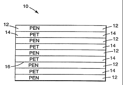
As indicated in FIGS. 1 a-b, the multilayer films 10 of the present invention
are formed from at least two different polymer resins. These resins are
coextruded
into a composite film having alternating layers of a first resin 12 and a
second resin
14. Preferably, either the first and second resins are immiscible, or the
coextrudate
is rapidly cooled to a temperature below the glass transition temperatures of
the
resins soon after the first and second resins come into contact with one
another
inside the coextrusion equipment. The satisfaction of one of these two
criteria
6
CA 02246447 1998-08-12
WO 97/32723 PCT/US96/11867
ensures that adjacent layers in the composite film are joined across an
interface 16,
which may be either sharp or diffuse.
The films of the present invention may contain virtually any number of layers
greater than or equal to three. However, there are preferably at least 7
layers in the
finished film, and more preferably at least 13 layers. The presence of at
least 7 or
13 layers in the film is found to coincide with the onset of certain desirable
properties, such as improvements in orientational stretchability, modulus, and
surface roughness. Typically, the films of the invention will contain only a
few
dozen layers, although finished films containing hundreds, or even thousands,
of
layers are found to be advantageous in some applications.
The layers of different resins are preferably arranged in an alternating
sequence in at least a portion of the film, and preferably throughout the film
as a
whole. However, in some embodiments, as in the embodiment depicted in FIG.
lb.,
the film may be extruded with one or more adjacent layers of the same resin.
In
most conventional extrusion processes, adjacent layers of the same resin will
coalesce into a single layer of greater thickness. This tendency may be used
to
produce doubly thick layers where the provision of such layers is desirable,
as on
the surfaces of some films.
The relationships among the thicknesses of the various layers is not limited.
Layers of the first resin may be different in thickness than lavers of the
second resin.
Different layers of the same resin may also be of different thicknesses.
The present invention also allows for virtually any number of layers of any
number of different resins to be incorporated into the multilayer film. Thus,
while
the multilayer films of the present invention will most commonly contain only
two
types of layers made from two different resins, the invention also
contemplates
embodiments wherein three or more different resin types are present in the
finished
film.
Many different polymer resins can be used to make multilayer films in
accordance with the present invention. However, as noted above, it is
preferred
that resins and/or processing conditions be chosen so as to maintain the
separate
7
CA 02246447 1998-08-12
WO 97/32723 PCT/US96/11867
chemical identity of the layers across an interface between each pair of
adjacent
layers.
The present invention contemplates that any polymer resins melt-
processable into film form may be used. These may include, but are not limited
to,
homopolymers and copolymers from the following families: polyesters, such as
polyethylene terephthalate (PET), polybutylene terephthalate, poly (1,4-
cyclohexylenedimethylene terephthalate), polyethylene bibenzoate, and
polyethylene
naphthalate (PEN); liquid crystalline polyesters; polyarylates; polyamides,
such as
polyamide 6, polyamide 11, polyamide 12, polyamide 46, polyamide 66, polyamide
69, polyamide 610, and polyamide 612; aromatic polyamides and
polyphthalamides; thermoplastic polyimides; polyetherimides; polycarbonates,
such
as the polycarbonate of bisphenol A; polyolefins, such as polyethylene,
polypropylene, and poly-4-methyl- I -pentene; ionomers such as SurlynTM
(available
from E.I. du Pont de Nemours & Co., Wilmington, Delaware); polyvinyl alcohol
and ethylene-vinyl alcohol copolymers; acrylic and methacrylic polymers such
as
polymethyl methacrylate; fluoropolymers, such as polyvinylidene fluoride,
polyvinyl
fluoride, polychlorotrifluoroethylene, and poly (ethylene-alt-
chlorotrifluoroethylene); chlorinated polymers, such as polyvinyl chloride and
polyvinylidene chloride; polyketones, such as poly(aryl ether ether ketone)
(PEEK)
and the alternating copolymers of ethylene or propylene with carbon monoxide;
polystyrenes of any tacticity, and ring- or chain-substituted polystyrenes;
polyethers, such as polyphenylene oxide, poly(dimethylphenylene oxide),
polyethylene oxide and polyoxymethylene; cellulosics, such as the cellulose
acetates; and sulfur-containing polymers such as polyphenylene sulfide,
polysulfones, and polyethersulfones.
Films in which at least one of the first resin and the second resin is a
semicrystalline thermoplastic, are preferred. More preferred are films in
which at
least one resin is a semicrystalline polyester. Still more preferred are films
in which
at least one resin is polyethylene terephthalate or polyethylene naphthalate.
Films
comprising polyethylene terephthalate and polyethylene naphthalate as the
first and
second resins are especially preferred, and the films thereof are found to
have many
8
CA 02246447 1998-08-12
WO 97/32723 PCT/US96/11867
desirable properties, including good orientational stretchability, high
modulus, and
controllable degrees of surface roughness, even in the absence of added slip
agents.
However, the exact choice of resins ultimately depends on the use to which the
multilayer films are to be applied. Thus, for example, if the multilayer film
is to be
used for optical applications, other factors, such as the indices of
refraction of the
resins, must be taken into account. Other pairs of polymer resins which
provide the
orientational stretchability, high modulus, and/or surface roughness
advantages
described herein are contemplated by the present invention.
Among the polyesters and copolyesters considered suitable for use in the
present invention are those formed as the reaction product of diols with
dicarboxylic acids and/or their esters. Usefizl diols include ethylene glycol,
propane
diol, butane diol, neopentyl glycol, polyethylene glycol, tetramethylene
glycol,
diethylene glycol, cyclohexanedimethanol, 4-hydroxy diphenol, bisphenol A, 1,8-
dihydroxy biphenyl, 1,3-bis(2-hydroxyethoxy)benzene, and other aliphatic,
aromatic, cycloalkyl and cycloalkenyl diols. Useful dicarboxylic acids include
terephthalic acid, isophthalic acid, any of the isomeric naphthalene
dicarboxylic
acids, dibenzoic acid, 4,4'-bibenzoic acid, azelaic acid, adipic acid, sebacic
acid, or
other aliphatic, aromatic, cycloalkane or cycloalkene dicarboxylic acids.
Esters of
the dicarboxylic acids may be used in place of or in combination with the
dicarboxylic acids themselves. When polyethylene terephthalate and
polyethylene
naphthalate are to be used as the first and second resins, either or both may
contain
minor amounts of comonomers and/or additives.
The intrinsic viscosity of the polymer resins to be used in the present
invention is not specifically limited. Depending on the equipment used for the
extrusion and casting of the multilayer film, the melt viscosities of the
polymer
resins may need to be matched to greater or lesser degrees of precision.
Monolayer
fiilms of PET are typically made from resins having intrinsic viscosities of
about
0.60. These and even lower IVs may also be accommodated in the present
invention. PET resins with IVs as high as 1.10 or higher may be routineiy
obtained
from commercial sources, and may also be used. The PEN resin should be chosen
9
CA 02246447 1998-08-12
WO 97/32723 PCT/US96/11867
so as to match the selected PET resin in melt viscosity closely enough, so
that
smooth, defect-free films may be cast with the equipment to be used.
Another aspect of the present invention concerns films having tailorable
surface roughness, haze, and coefficient of friction, without the use of
conventional
"slip agents". Tailorable surface roughness is desirable so as to provide
films
appropriate to diverse applications. For instance, films employed as
substrates for ,.
magnetic recording media must be relatively smooth on the side or sides to
which
the magnetic coating is applied. Typical requirements are for root mean square
average surface roughness (Rq) of less than 60nm, with many applications
requiring
Rq less than 20nm, and some requiring Rq less than l Onm. On the other hand,
capacitor films and printable or writeable films must have a high surface
roughness
to allow oil impregnation and to accept ink, respectively. Typical
requirements in
these applications are for Rq values greater than 100nm, with some
applications
requiring Rq values of 200nm or more.
Haze is well-known in the film industry to correlate with roughness,
especially in the absence of complicating factors such as particulate
additives.
Furthermore, haze is considerably easier to measure and/or qualitatively
assess than
is surface roughness. Thus, while of interest in its own right for certain
applications, haze was typically assessed, in the experiments described
herein, as a
means of making qualitative comparisons of the surface roughnesses of films.
A low coefficient of friction is desirable so as to improve handling and
winding properties of the film during manufacture and use, and to prevent
blocking
during storage. Thinner films are known to require lower coefficients of
friction in
order to be wound and handled without damage such as wrinkling and web breaks.
Coefficient of friction also correlates well with surface roughness, provided
that
composition and construction within a series of films remains unchanged. Thus,
for
polyethylene terephthalate films containing a given slip agent, increasing the
amount
of the slip agent increases the surface roughness, and lowers the coefficient
of
friction in a well-correlated manner. The form of the correlation may differ
for a
different slip agent, however.
CA 02246447 1998-08-12
WO 97/32723 PCT/US96/11867
Slip agents are so named because the purpose of their use in films is to
provide a low coefficient of friction (i.e., slipperiness) required for
handling. Slip
agents are defined as inert solid fine particles within, or on, the surface(s)
of the
film. They may be incorporated into the film during its formation, or coated
onto
the film's surface afterward. When coated on, they may be incorporated in a
binder
polymer, which may or may not be the same polymer as the film itself, or they
may
be deposited from a dispersing medium or solvent. When incorporated into the
film
during its formation, they may be present throughout the film, or only in
layers
coextruded or laminated on one or both surfaces. Slip agents may be
incorporated
by blending them into the film polymer resin during extrusion, or they may be
incorporated into the resin during its manufacture.
Slip agents may be spherical or non-uniform in shape. They may or may not
form agglomerates. Individual slip agent particles usuall_y are smaller than 5
microns in diameter, and are most commonly an order of magnitude or more
smaller
than that. They are incorporated into films at up to about 3% by weight, but
more
typically are present at well under 1%.
Slip agents can be polymeric or non-polymeric. Typical examples of non-
polymeric slip agents are kaolin, talc, silicas, aluminas, metal carbonates
such as
calcium carbonate, metal oxides such as titanium dioxide, silicate salts,
metal
phosphates, metal sulfates, metal titanates, metal chromates, metal benzoates,
metal
terephthalates, forms of carbon such as carbon black, and glasses. Polymeric
slip
agents may be crosslinked or non-crosslinked. Typical examples of crosslinked
polymeric slip agents are silicones, styrenics, acrylics, and polyesters. Non-
crosslinked polymeric slip agents are typically thermoplastics, and they are
processed so as to be finely dispersed as particles within the film resin.
Typical
examples of non-crosslinked polymeric slip agents are polyolefins, ionomers,
styrenics, polycarbonates, acrylics, fluoropolymers, polyamides, polyesters,
polyphenylene sulfide, and liquid crystalline polymers.
All conventional slip agents have in common a fine particulate nature in, or
on the surface(s) of, the finished film. Furthermore, all conventional slip
agents of
the type that are incorporated into the film during its formation (rather than
coated
11
CA 02246447 1998-08-12
WO 97/32723 PCT/US96/11867
on afterward) have in common a fine particulate nature in, or on, the
surface(s) of
the extruded cast web as well. For this reason, there are significant
disadvantages
to the use of slip agents. The use of slip agents necessitates the use of
filtration
devices in the manufacture of the film. These devices are frequently ciogged
by the
slip agent. Also, slip agents may form undesirably large agglomerates in the
film,
which have a negative effect in many applications. Incorporation of inorganic
particulates usually requires that they be milled to the appropriate size
and/or
"classified". These are added steps that are difficult to control and add
cost.
Incorporation of crosslinked polymer particles requires either similar
preparation, or
precise control of particle shape and size during their formation.
Incorporation of
non-crosslinked polymer particles requires difficultly-obtained control over
their
size distribution and/or dispersion during film extrusion. Furthermore, the
use of
slip agents presents the possibility for the formation of dust and debris, and
scratching of the film surface, during biaxial orientation, handling, winding,
slitting,
converting, processing and/or use of the film.
For all these reasons, it is desired to control surface roughness and
coefficient of friction in polymer films without resort to the addition of
conventional
inert solid fine particulate slip agents. Surprisingly, it lias been
discovered that the
multilayer films of the present invention possess varying degrees of surface
roughness and "slip" (coefficient of friction), even in the absence of slip
agents, and
that the degree of surface roughness and value of coefficient of friction is
adjustable
by varying process conditions, such as the temperature and duration of
preheating
prior to orientation.
In the Examples set forth below, the following procedures were used to
determine the physical properties of the films tested.
Intrinsic Viscosity:
Intrinsic viscosity was determined identically for both PEN and PET. The
solvent used is a 60/40 mixture (by weight) of phenol and ortho-
dichlorobenzene.
A temperature of 110 C is used to effect the dissolution of the polymer in 30
minutes. A size 150 Cannon-Fenske viscometer is used, and data is taken at 30
C.
12
CA 02246447 1998-08-12
WO 97/32723 PCT/US96/11867
A single-point determination of relative viscosity is done, using a solution
concentration of about 0.5% polymer by weight. Relative viscosity is the ratio
of
eflIux times in the viscometer for the solution and the pure solvent. The
relative
viscosity is converted to an approximate value of intrinsic viscosity using
the well-
known Billmeyer relationship:
IV = {rI(rel)-l+3In[rI(rel)]}/4c
where 71(reI) is the relative viscosity and c is the polymer solution
concentration in
g/dL.
Modulus Measurement:
Modulus was measured on a computerized Instron tensile tester. Specimens
were cut to 0.5 inch width. The gauge length between Instron grips was 4
inches.
The test was performed at a rate of 2 inch/min crosshead speed. The specimens
were cut to approximately 7 inch lengths to permit easy mounting in the 1 inch
wide
Instron grips and great care was taken to avoid either excessive slack or pre-
tension
for these thin film specimens. The thickness for each specimen was determined
by
taking ten measurements within the gauge length. The average of all ten was
used
in calculations. For films prepared on a continuous film line, specimens were
cut
from the center of the web. For films prepared on a laboratory film stretcher,
tensile specimens were cut from the center of the square specimen from the
stretcher. In this case, specimens for determining the tensile properties in
the
machine direction were taken from one square stretcher specimen, and specimens
for determining the tensile properties in the transverse direction were taken
from a
separate square stretcher specimen, so that all could be cut from the center.
In
some evaluations, five specimens were cut and tested, and the values obtained
were
averaged. Variation was small, however, so for most evaluations only three
specimens were tested and averaged.
In some examples, a value is given for the "Green modulus". It was
discovered that the modulus of the films made in these studies increased over
time.
13
CA 02246447 1998-08-12
WO 97/32723 PCT/US96/11867
While this is not uncommon for biaxially oriented polyester films, in some
cases the
increase was more dramatic than that which is normally observed for PET films.
Thus, modulus measurements were made either as soon as possible (and no more
than four hours after the film was made), or after at least one week had
elapsed. It
is believed that most if not all of the modulus enhancement or "aging" occurs
in the
interim. Measurements taken on "aged" film are referred to simply as
"modulus",
while measurements taken quickly are referred to as "green" modulus. Most
reported values for green modulus represent the average of two tests.
Reversible Coefficient of Thermal Expansion:
The Reversible Coefficient of Thermal Expansion, or CTE, was measured
using a Zygo model 121 testing apparatus. A 0.5 inch wide, 12 inch long test
specimen is mounted flat. The temperature differential used for testing was
approximately 20-25 C, going from Room Temperature to about 45 C. The CTE is
measured as mm of expansion per mm of initial length per C of temperature
change. Since the expansion is typically on the order of 1-20 x 10-6 in these
units, it
is reported as parts per million per C (ppm/ C). For most films tested, three
specimens were prepared and the results were averaged.
Reversible Coefficient of Hygroscopic Expansion:
The Reversible Coefficient of Hygroscopic Expansion, or CHE, was
measured on a Neenah Paper Expansimeter. A 0.5 inch (1.27 cm) by 9.5 inch
(24.13 cm) sample is arranged in the apparatus between a hook and a level/hook
arrangement. A micrometer is used to adjust the level after a change to the
test
specimen length occurs due to controlled change in the humidity of the air in
the
test apparatus. The humidity test range was 23-94 % relative humidity (%
R.H.).
CHE is measured as mm of expansion per mm of initial length per % R.H.
Similarly
to the CTE, the values for CHE are conveniently expressed as ppm/% R.H. Again,
most results represent the average of three tests.
14
CA 02246447 1998-08-12
WO 97/32723 PCT/US96/11867
Irreversibie Thermal Shrinkage:
Thermal shrinkage was measured as follows: Test specimens were cut to
0.5 inch (1.27 cm) width and 12 inches (30.48 cm) in length. Ink "X"-niarks
were
placed about 10 inches (25.4 cm) apart on each specimen. The exact distance
between the two marks was determined by using an "optical comparitor" or
"electronic ruler", a device which precisely determines the distance traveled
by a
microscopic eyepiece moved from one mark to the other. The specimens were then
allowed to hang unrestrained in a temperature-controlled oven for 3 days (72
hrs) at
80 C. The specimens were removed from the oven and remeasured. Great care is
taken during both measurements to ensure that the specimens are mounted on the
optical comparitor flat and straight, and with as little tension as possible.
Shrinkage
results are expressed as a percent of the original specimen length, and are
regarded
as accurate to +/- 0.01%. Here too, results are expressed as the average of
three
tests. In some evaluations, the oven conditions were changed to 3 days
residence
time at 65 C. Some measurements were also done for 15 minutes residence time
at
150 C.
Haze:
Haze was measured with a Gardner Hazemeter. Model AUX- 10 or AUX-
l0A was used, with a sample size of approximately 1 inch (2.54 cm) square.
Care
was taken to ensure that the film specimens were free from dust, scratches,
etc.
Light passing through the sample either directly, or "diffused", is captured
and
quantified by the instrument. Haze is the amount of diffused transmitted light
as a
percentage of all transmitted light (direct and diffuse).
Coefficient of Friction:
Static and Kinetic Coefficients of Friction were measured with an Instron
tensile tester. In this document, all coefficients of friction are measured on
films
made to slide with one of their surfaces in contact with the opposite surface.
A 2
inch (5.08 cm) wide and 10 inch (25.4 cm) long specimen is cut from the film
and
mounted on a horizontal platform. A 1 inch (2.54 cm) wide by 5 inch (12.7 cm)
CA 02246447 1998-08-12
WO 97/32723 PCT/US96/11867
long specimen is cut from the film and mounted on a special 200 gram "sled"
with a
0.97 inch (2.46 cm) radius. The specimens are cut so that the film's machine
direction is in the long dimension of each specimen. The sled is placed on the
platform, and pulled with a chain via a pulley by the Instron crosshead at 1/2-
inch
per minute (2.Ix10-2 cm/s). At least 4 inches (10.16 cm) of crosshead travel
is
used.
The coefficient of friction is defined as the ratio of the Frictional Force to
the sled weight. The Frictional Force is read directly from the Instron
recorder
chart. The Static Coefficient of Friction is determined by using the peak
force
recorded at the beginning of the test. The Kinetic Coefficient of Friction is
determined by using the average force recorded at long times in the test.
Surface Roughness by Interferometer:
Surface roughness is measured on a specially-constructed instrument
utilizing the principles of laser light interferometry. Specimens are cut from
the film
1/2-inch (1.27 cm) wide by 6 inches (15.24 cm) long, and are vapor coated with
metal. As configured, the system probes an area about 230 microns wide bv 365
microns long. A 3-dimensional image of the probed area is generated.
Statistical
parameters of the surface are also calculated by the instrument's dedicated
computer. Normally, two averages, "Ra" and "Rq", both well known to those
experienced in surface profilometry, are reported. Ra is the arithmetic mean
height
of deviations from the hypothetical average plane of the film surface. Rq is
the
geometric mean height of deviations from the same plane.
Surface Roughness by Rodenstock:
In some cases, films of the current invention proved so rough as to be
outside the useful range of the Interferometer, above. Thus, a second method
was
employed, using the Rodenstock RM600 surface analyzer, a commercially
available
instrument. The Rodenstock is a non-contact surface "stylus" which probes the
specimen along a 5 mm long line, rather than canvassing a rectangular area,
and
works on the principle of dynamically refocusing a laser beam on the traveling
film
16
CA 02246447 1998-08-12
WO 97/32723 PCT/US96/11867
surface. Specimens for Rodenstock must also be vapor coated. The Rodenstock
technique also calculates Ra and Rq, but due to the way the data is collected,
filtered, and analyzed, it returns consistently higher values than the
Interferometer,
for the same specimen. Thus, values of Ra and Rq from the two instruments
cannot
be usefully compared.
EXAMPLES 1-24
The following examples demonstrate the ability to coextrude PEN and PET
into multilayer webs at various combinations of intrinsic viscosities with
either
polymer at the two film surfaces, throughout the full range of relative
composition.
Several webs of PEN and PET were cast by coextrusion. The webs
consisted of alternating layers (usually 29 total) of PEN and PET, which were
obtained from the Goodyear Chemical Co., Akron, Ohio. In each web, the two
surface layers (the I st and 29th) consisted of the same polymer. As shown in
Table
1, in some coextrusions, both of the surface layers consisted of PEN, while in
others, both surface layers consisted of PET.
Several different molecular weights for each resin were used in the
experiments, as reflected in the values for Intrinsic Viscosity reported in
Table 1.
The polymers were extruded on separate 1-3/4" (4.4 cm) single screw extruders.
PEN was extruded at about 293 C, and PET was extruded at about 282 C. The
throughput of each extruder was adjusted within the range of 5.22 kg/hr
(1.45x10⁻³)
to about 43.5 kg/hr (1.2x10⁻²) so as to arrive at the polymer proportions
shown in
Table 1. A film die which accepts modular coextrusion inserts was used with an
insert machined for 29-layer coextrusion. The die had an orifice width of 12
inches
(30.48 cm), and was maintained at about 282 C. Extrudates were cast onto a
chilled roll maintained at about 22 C for the purpose of quenching the cast
webs to
a solid amorphous state. The quenched cast webs were about 12-13 mils thick.
17
CA 02246447 1998-08-12
WO 97/32723 PC'd'/US96/11867
TABLE 1
Example PEN IV PET IV "Surface" % PEN
No. (dL/ (dL/g) Polvmer
1 0.57 - All-PEN Control 100
2 0.57 0.80 PET 80
3 0.57 0.80 PET 71
4 0.57 0.80 PET 59
0.57 0.80 PET 49
6 0.57 0.80 PET 41
7 0.57 0.80 PET 31
8 0.57 0.80 PET 20
9 - 0.80 All-PET Control 0
0.50 - All-PEN Control 100
11 0.50 0.72 PET 70
12 0.50 0.72 PET 59
13 0.50 0.72 PET 49
14 0.50 0.72 PET 39
0.50 0.72 PET 30
16 0.50 0.72 PET 16
17 - 0.72 All-PET Control 0
18 0.50 0.95 PEN 71
19 0.50 0.95 PEN 60
0.50 0.95 PEN 49
21 0.50 0.95 PEN 41
22 0.50 0.95 PEN 29
23 0.50 0.95 PEN 20
24 - 0.95 All-PET Control 0
EXAMPLES 25-35
The following examples demonstrate the enhancement in modulus and
5 stretch ratios of the multilayer films of the present invention in
comparison with
monolayer PEN.
18
CA 02246447 1998-08-12
WO 97/32723 PCT/US96/11867
The cast webs made in Examples 1-2 above were stretched into films using a
laboratory biaxial film stretching device. The stretching device was a custom-
built
instrument using a pantograph mechanism similar to that found in commercial
instruments of its kind, such as the film stretchers available from T. M. Long
Co. A
square specimen of the cast web was marked with a gridline pattern and then
mounted inside the film stretcher, with the temperature inside the stretcher
at or just
below 100 C. The temperature was quickly raised to 150 C and the sample was
held for 45 seconds, measured from the beginning of the temperature rise. The
sample was then stretched simultaneously and equally in the machine and
transverse
directions at a rate of 100%/s, based on the original gauge length of the
sample.
The gauge length is defined as the distance between opposing pairs of
grippers, as
measured between their closest points. The stretching chamber was then opened
and the sample was quenched by blowing cool air across its surface and was
then
removed.
Stretch ratios for stretched samples were determined as the nominal stretch
ratio and the real stretch ratio. "Nominal stretch ratio" refers to the final
sample
length divided by the gauge length, as determined by grip separation. "Real
stretch
ratio" refers to the analogous figure, as measured by displacement of the
central
marks of the gridline pattern which had been printed on the sample. As used
throughout this specification, the phrase "biaxial stretch ratio" refers to
the nominal
stretch ratio (in each direction) for a simultaneous stretch of equal
magnitude in
each direction. Real stretch ratios and modulus values reported without
reference
to machine or transverse directions are averaged values for the two
directions.
Specimens were prepared from the cast webs made in Examples 1(100%
PEN) and 2 (20% PET, 80% PEN). These specimens were stretched to various
biaxial stretch ratios, until a stretch ratio was found at which it was
difficult to
stretch without specimen failure. The resulting stretched films were tensile
tested to
determine their Young's Moduli. The results of these stretching experiments
are
shown in Table 2.
19
CA 02246447 1998-08-12
WO 97/32723 PCT/US96/11867
TABLE 2
Example Cast Web from % Nominal Real Stretch Modulus, kpsi
No. Example No. PEN Stretch Ratio Ratio (106 kPa)
25 1 100 3.50 3.74 858 (5.9)
26 1 100 4.00 4.00 910 (6.27)
27 1 100 4.50 4.41 982 (6.77)
28 1 100 5.00 4.78 1043 (7.19)
29 1 100 5.25 5.10 1078 (7.43)
30 2 80 3.50 3.50 731 (5.04)
31 2 80 4.00 3.89 835 (5.76)
32 2 80 4.50 4.36 916 (6.32)
33 2 80 5.00 4.70 995 (6.86)
34 2 80 5.50 5.19 1066 (7.35)
35 2 80 5.75 5.51 1181 (8.14)
These results are depicted graphically in FIG. 2. FIG. 2 demonstrates that
each composition develops a monotonically increasing Young's Modulus as the
simultaneous biaxial stretch ratio is increased. At any given stretch ratio
not
resulting in sample failure, PEN shows a higher modulus than the 20:80 PET:PEN
multilayer film, a result that might be expected in light of the fact that PEN
is
known to be a higher modulus polymer than PET. However, the multilaver cast
web is unexpectedly capable of being stretched to a considerably higher
stretch ratio
without sample failure as compared to monolithic PEN. Consequently, the
modulus
of the multilayer film is seen to ultimately surpass that of the PEN film,
which is
stretchable only to a lower stretch ratio.
EXAMPLES 36-44
The following examples demonstrate the effect of the PEN:PET Ratio on
stretchability and modulus.
Experiments were performed to determine the highest stretch ratio to which
the cast webs of Examples 1-9 could be stretched at the conditions of Examples
25-
CA 02246447 1998-08-12
WO 97/32723 PCT/US96/11867
35. The breaking of a film during stretching is a statistical event, so that
different
specimens cut from a given cast web will stretch to varying extents before
breaking.
For the purpose of these examples, the stretch ratio was examined at
increments of
0.25 nominal stretch ratio units until a ratio was found at which the sample
broke
during stretching. This condition was repeated until three consecutive sample
failures were recorded, or until two samples stretched without breaking. The
highest value of stretch ratio to which a stretching experiment could be
completed
and replicated without specimen rupture is called the Ultimate Biaxial Stretch
Ratio
(LJBSR). Corresponding Real Stretch Ratios were determined as in Examples 25-
35, by the displacement of ink marks.
At the UBSR for each composition, specimens were tensile tested to
determine their Young's Moduli. Some of these films were also mounted under
restraint on metal frames, and heat-set in an oven. The oven was allowed to
equilibrate at 235 C, the door was quickly opened, the framed specimen
inserted,
and the door immediately closed. The specimen was left in the oven for 30
seconds
and then removed. These heat-set specimens were also tensile tested for
Young's
Modulus. The UBSR, Modulus, and Heat-set Modulus results are shown in tabular
form in Table 3 and graphically in Figures 3 and 4.
21
CA 02246447 1998-08-12
WO 97/32723 PCT/US96/11867
TABLE 3
Example Cast Web % PEN UBSR UBSR Modulus, Heat-Set
No. from (nom) (real) kpsi Modulus, kpsi
Example (106 kPa) (106 kPa)
No.
36 1 100 5.25 5.10 1078 1178
(7.43) (8.12)
37 2 80 5.75 5.51 1181 1304
(8.14) (8.99)
38 3 71 5.75 5.46 1071 1197
(7.38) (8.25)
39 4 59 5.25 5.00 1005 1124
(6.93) (7.75)
40 5 49 5.00 4.61 948 1047
(6.54) (7.22)
41 6 41 4.25 3.88 811 ---
5.59)
42 7 31 3.50 3.06 648 ---
4.47
43 8 20 3.25 2.86 556 ---
(3.83
44 9 0 3.00 2.07 443 ---
(3.05)
As shown in Table 3 and FIG. 3, the UBSR varies smoothly with
composition for the cast webs of Examples 1-9, with a maximum value near a
composition of 70 to 80% PEN. For multilayer specimens consisting of at least
about 60% PEN, these values are about as higll, or higher, than those observed
with
samples consisting of 100% PEN. Since PET itself is known generally to be less
stretchable than PEN, it is an unexpected result that the multilayer films of
the two
polymers should stretch to higher ratios than either polymer alone.
Table 3 and FIG. 4 clearly show that the dependence of the modulus on the
composition, when measured at the UBSR, follows the same general shape, that
the
modulus is highest near a composition of 80% PEN, and that any of these
multilayer
compositions having at least about 70% PEN is capable of having a modulus
equal
to or greater than that of 100% PEN. Since PET is known generally to be a
polymer of lower modulus than PEN, it is particularly unexpected that the
multilayer films of the two polymers should have Young's Moduli higher than
those
22
CA 02246447 1998-08-12
WO 97/32723 PCT/US96/11867
of either PEN or PET alone. Table 3 and Figure 4 also illustrate the effect of
heat-
setting in improving the modulus of any of the films of this invention.
EXAMPLES 45-57
The following examples illustrate the linear dependence of the modulus of
the multilayer compositions of the present invention on (% PEN) and the real
stretch ratio.
Additional specimens were prepared from the cast webs of Examples 3-6.
These were stretched to biaxial stretch ratios of 3.5 or higher, and their
moduli were
determined as before. The results are shown in Table 4. The data from Examples
25-57 were pooled and fitted to a mathematical model, assuming that the
modulus
depends linearly on both the composition (% PEN) and the real stretch ratio.
TABLE 4
Example Cast Web of % Stretch Ratio Stretch Ratio Modulus, kpsi
No. Example No. PEN (nom) (real) (106 kPa)
45 3 71 3.50 3.39 741 (5.11)
46 3 71 4.00 3.97 824 (5.68)
47 3 71 4.50 4.31 903 (6.23)
48 3 71 5.00 4.72 992 (6.84)
49 3 71 5.50 5.14 1034 (7.13)
50 4 59 4.00 3.80 787 (5.43)
51 4 59 4.50 4.22 886 (6.11)
52 4 59 5.00 4.74 956 (6.59)
53 5 49 3.50 3.30 727 (5.01)
54 5 49 4.00 3.68 804 (5.54)
55 5 49 4.50 4.20 872 (6.01)
56 6 41 3.50 3.22 707 (4.87)
57 6 41 4.00 3.68 747 (5.15)
23
CA 02246447 1998-08-12
WO 97/32723 PCT/US96/11867
The result of the mathematical fit is shown graphically in FIGS. 5 and 6. It
is immediately apparent that the data is well-fit by a linear model. The model
also
yields reasonable values for several limiting cases. Thus, FIG. 5 shows that
the
model predicts a modulus for pure PET biaxially oriented to a stretch ratio of
4.0
that is roughly 760 kpsi (5.24x10⁶ kPa). This value is comparable to those
observed with PET films made by conventional industrial processes. The model
also predicts a modulus for pure PEN biaxially oriented to a stretch ratio of
5.0 that
is roughly 1070 kpsi (7.38x10⁶ kPa), which is comparable to the values
observed
with commercially available PEN films. FIG. 6, which shows a wider view of the
same model, shows that the modulus values at stretch ratio of 1.0 are roughly
260
kpsi (1.79x10⁶ kPa) and 350 kpsi (2.41x10⁶ kPa) for PET and PEN, respectively.
These values also compare reasonably with those observed for pure samples of
the
polymers in question in their unstretched states.
These results imply that the assumptions of the model are reasonable, and
that the extrapolations of the other lines of constant stretch ratio in FIG. 6
are also
significant. This suggests that the contribution of the PET layers to the
overall
modulus of the multilayer films stretched to stretch ratios of 5.5 is slightly
in excess
of 1000 kpsi (6.9x10⁶ kPa). It must be noted that a monolayer free-standing
film of
PET typically cannot be stretched to stretch ratios as high as 5.5 in each
direction
by known commercial processes, and that the modulus of PET film made by such
processes does not reach values in excess of 1000 kpsi (6.9x 10⁶ kPa) in each
direction.
Therefore, the results obtained in these examples, and the success of the
linear model in predicting the observed results, imply that the PET layers
within the
multilayer films are stretchable to much higher draw ratios than can be
achieved in
conventional processes, and possess moduli far in excess of those attainable
with
conventional PET films. A PET-layer "contribution" to the overall film modulus
of
over 1000 kpsi (6.9x10⁶ kPa) is a particularly surprising result, as is the
stretchability of PET layers to stretch ratios of 5.5.
24
CA 02246447 1998-08-12
WO 97/32723 PCT/US96/11867
EXAMPLES 58-61
The following examples demonstrate the dimensional stability of the films of
the present invention.
Multilayer film samples from cast webs 1, 2, 3, and 9 were prepared by
stretching, simultaneously and equally in both directions, on the laboratory
film
stretcher. Conditions are given in Table 5. The stretch ratios chosen for each
cast
web were at or near the UBSR for the chosen stretch temperatures. The films
were
heat-set on frames as in Examples 36-40. The CTE, CHE, and 80 C/3 day
shrinkage were measured on specimens cut on the diagonal, so as to average the
effects of the two directions. The results are presented in Table 5.
TABLE 5
Example Cast % PEN Stretch Biaxial CTE CHE (ppm/ Shrink-
No. Web Temp. Stretch (ppm/ C) % RH) age
No. ( C) Ratio (%)
58 9 PET 100 3.75 17.74 10.05 0.38
Control
59 1 PEN 150 5.0 6.13 9.83 0.15
Control
60 2 80 150 6.0 4.68 9.25 0.20
61 3 71 150 5.5 3.97 9.02 0.21
The results clearly reflect the well-known superior dimensional stability of
PEN over PET. Moreover, the results also show that the multilayer films
exhibit
somewhat improved CTE and CHE values over even the pure PEN film, and
shrinkage values roughly equivalent to that which would be obtained from an
interpolation based on composition between the values of the PET and PEN
films.
EXAMPLES 62-88
The following examples illustrate the effect of temperature on stretchability
and modulus.
Stretching experiments were performed on specimens of the cast web of
Example 2 to determine the effect of temperature on stretchability and the
resulting
CA 02246447 1998-08-12
WO 97/32723 PCT/US96/11867
modulus. The procedures followed were similar to those of Examples 36-44
above,
except that the temperature was varied from 150 C. UBSRs were determined at
temperatures from 120 to 180 C. In these Examples, the UBSR is expressed only
in terms of the nominal stretch ratio to save the effort of measuring Real
stretch
ratios. Also, in these Examples, a stretch ratio condition was pursued until
five
consecutive sample failures were recorded (rather than three). Thus, the
values
reported for UBSR will be slightly higher if compared to those in Examples 36-
44.
The laboratory stretcher used was capable of a maximum stretch ratio only
slightly in excess of 6Ø At temperatures from 155 to 175 C, the UBSR was
found
to be in excess of 6.0, as evidenced by the lack of ruptured specimens when
stretched to this extent. Therefore, in order to more fully gauge the
temperature
effect, the somewhat less stretchable cast web of Example 5 was also tested.
The Young's Modulus of each film stretched to its LJBSR was determined
by tensile testing. The results are shown in Table 6 and in FIGS. 7-8. It was
observed that all of the films had a patchy or broken "frosted" or hazy
appearance
on each surface.
TABLE 6
Example Cast Web % PEN Stretch UBSR Modulus at
No. of Example Temperature, UBSR, kpsi
No. C (106 kPa)
62 2 80 120 4.00 632 (4.36)
63 2 80 125 4.50 665 (4.59)
64 2 80 130 4.50 799 (5.51)
65 2 80 135 4.75 885 (6.10)
66 2 80 140 5.00 931 (6.42)
67 2 80 145 5.50 968 (6.67)
68 2 80 150 6.00 1028 (7.09)
69 2 80 155 > 6.00 ---
70 2 80 160 > 6.00 ---
71 2 80 165 > 6.00 ---
72 2 80 170 > 6.00 26
CA 02246447 1998-08-12
WO 97/32723 PCT/US96/11867
Example Cast Web % PEN Stretch UBSR Modulus at
No. of Example Temperature, UBSR, kpsi
No. C (106 kPa)
73 2 80 175 > 6.00 ---
74 2 80 180 Unstretch- ---
able
= 75 5 49 120 3.75 ---
76 5 49 125 4.25 ---
77 5 49 130 4.25 726 (5.01)
78 5 49 135 4.50 799 (5.51)
79 5 49 140 4.50 774 (5.34)
80 5 49 145 4.75 807 (5.56)
81 5 49 150 4.75 864 (5.96)
82 5 49 155 5.00 886 (6.11)
83 5 49 160 5.25 861 (5.94)
84 5 49 165 5.50 ---
85 5 49 170 5.50 664 (4.58)
86 5 49 175 5.25 ---
87 5 49 180 5.25 ---
88 5 49 185 4.75 ---
FIG. 7 shows that the UBSR for the 80% PEN multilayer achieves a
maximum at a temperature somewhere between 150 and 180 C, falling off sharply
at the high-temperature end of the range. The UBSR also appears to fall off
more
abruptly as the stretch temperature is lowered below 125 C, which is very near
the
Tg of PEN. The 49% PEN composition exhibits a similarly dependence of UBSR
on stretch temperature, although the UBSR falls off more gradually at very
high
temperatures as compared to the 80% PEN composition.
This effect may be due in part to the crystallization of the PET before the
stretching commences at these high temperatures. Generally, 170-180 C is
regarded as the temperature range in which PET crystallizes from the amorphous
27
CA 02246447 2006-04-11
60557-5897
glass most rapidly. With PET making up more of the total in the 49% PEN
composition, the sample may be better able to support drawing stresses at the
higher temperatures. It is also apparent that the 49% PEN composition has a
maximum UBSR at 165-170 C.
As indicated in FIG. 8, the modulus at the UBSR for the 80% PEN
composition rises with stretch temperature up to the point where machine
limitations make further measurements impossible. The modulus of the film made
at 150 C was in excess of 1000 kpsi (6.9x10⁶ kPa) prior to heat-setting, and
the
curve of modulus as a function of stretch temperature shows no signs of
leveling
off. The results for the 49% PEN composition, however, show a maximum at a
stretch temperature somewhat lower than that of the UBSR maximum. Thus, the
optimum stretching temperature range for the 80% PEN composition is also
likely
to be in the 150-160 C range. Since the glass transition of PEN is only about
120-
125 C and the glass transition of PET is much lower, the determination of an
optimum stretching temperature of 150-160 C for'the multilayer films is a
surprising
result.
EXAMPLES 89-103
The following examples illustrate the application of the feedblock concept of
multilayer coextrusion for the PEN:PET polymer pair.
Samples of PEN and PET were obtained and were dried under dry nitrogen,
PEN at about 177 C, and PET at about 149 C. The PEN resins used had several
different molecular weights, as measured by intrinsic viscosity (IV). The PET
resin
TM
was Goodyear Traytuf 8000C, with an IV of 0.80. For PEN, a 1-3/4 inch extruder
was used, and the extrusion temperature was about 293 C. For PET, a second
1.75
inch (4.4 cm) extruder was used, and the extrusion temperature was about 282
C.
The resins were coextruded by a feedblock method. Thus, the melt streams
from the two extruders were conveyed to the feedblock via 3/4" diameter neck
tubes maintained at about 293 C and 266 C, respectively, for PEN and PET. A
modular feedblock with an alternating-two-component, 29-layer insert was used.
The feedblock fed a typical polyester film die with a 12 inch (30.5 cm) wide
die
28
CA 02246447 1998-08-12
WO 97/32723 PCT/US96/11867
orifice. The feedblock exit was mated to the die inlet via a gradual square-to-
round
flow channel profile adapter.
The feedblock, adapter, and die were all maintained at about 282 C. The
extrudate was cast onto a chill roll maintained at about 18 C, and
electrostatic
pinning was used. Total combined throughput was maintained at either about 60
lbs/hr (7.5x10⁻³ kg/s) or 90 lbs/hr (1.1x10'a kg/s). The PEN:PET ratio was
varied
from about 80:20 to about 50:50. The feedblock was set up so that the
outermost
layers were PET in some experiments and PEN in others. The cast web thickness
was controlled by the chill roll speed to be about 12-13 mils. In some
experiments,
the 2nd and 28th slots of the feedblock were plugged, so as to create a 25-
layer
flow with outermost layers of double thickness.
The cast films were evaluated before any stretching for characteristic
rheologically-based flow-defect patterns, and rated "Good", "Marginal", or
"Poor".
"Good" cast webs exhibited no flow-defect patterns, "Marginal" webs exhibited
minor cosmetic flow-defect patterns, and "Poor" webs exhibited significant
flow-
defect patters. Table 7 contains the conditions of the individual experiments
and
results of the evaluations.
TABLE 7
Example No. of PEN IV, Through- PEN:PET Outside Cast
Number Layers dL/g put, lbs/hr Ratio Layer Web
Ratin
(10-' kg/s) Polymer
89 29 0.626 63 (7.9) 80 PET Poor
90 29 0.570 59 (7.4) 80 PET Poor
91 29 0.520 61(7.7) 81 PET Poor
92 29 0.473 61 7.7) 80 PET Good
93 29 0.473 62 (7.8) 70 PET Good
94 29 0.473 62 (7.8) 61 PET Good
95 29 0.473 61(7.7) 53 PET Marginal
96 25 0.570 60 (7.6) 79 PET Poor
97 25 0.516 59 (7.4) 80 PET Marginal
98 25 0.516 94 (11.8) 79 PET Marginal
29
CA 02246447 1998-08-12
WO 97/32723 PCT/US96/11867
Example No. of PEN IV, Through- PEN:PET Outside Cast
Number Layers dL/g put, lbs/hr Ratio Layer Web
(10-3 k s Polymer Rating
99 25 0.485 63 (7.9) 80 PET Good
100 25 0.485 93 (11.7) 80 PET Good
101 25 0.555 61(7.7) 79 PEN Poor
102 25 0.516 59 (7.4) 79 PEN Marginal
103 25 0.485 60 (7.6) 78 PEN Good
These results indicate that, with the feedblock configuration used, it was
necessary to utilize a PEN resin with IV below 0.52 in order to make
acceptable
multilayer cast webs with a PET resin of IV 0.80, regardless of which polymer
was
used on the surface layers. The same feedblock and die were used in subsequent
experiments on continuous film lines. Since the mechanical properties of PEN
decrease with an IV below a level of about 0.53, comparison of properties
between
prior and subsequent examples may be misleading.
EXAMPLES 104-105
The following examples illustrate the effect of IV on stretchability.
Specimens were prepared for stretching experiments from the cast webs of
Example 3 (for Example 104) and Example 11 (for Example 105). These cast webs
were chosen because the only significant difference between them was the IV of
the
resins used. The cast web of Example 3 consisted of PEN with IV of 0.57 and
PET
with IV of 0.80. The cast web of Example I 1 consisted of PEN with IV of 0.50
and PET with IV of 0.72. Each cast web had PET at the outermost layers, and
consisted of about 70% PEN.
For each cast web, the UBSR was determined as in Examples 50-76, at
150 C. In Example 104, the UBSR was determined to be 5.75. In Example 105, a
value of 5.25 to 5.50 was obtained. Thus, the higher IV resins appear to
promote
the enhanced stretchability effect.
CA 02246447 1998-08-12
WO 97/32723 PCT/US96/11867
EXAMPLES 106-111
The following examples illustrate the effect of cast web quality on
stretchability.
Specimens were prepared for stretching experiments from the cast webs of
Example 2 (for Example 106) and Example 90 (for Example 107). These cast webs
were chosen because the only significant difference between them was that the
web
from Example 2 was prepared using the multilayer die, while the web from
Example
90 was prepared using the less rheologically "forgiving" multilayer feedblock.
Thus, the web from Example 90 included rheologically-related surface
imperfections, as reflected by its cast web rating of "poor" in Table 7. Each
cast
web consisted of 80% PEN and had PET as the outermost layers. The resins used
in the web also had similar IVs.
For each cast web, the UBSR was determined as in Examples 62-88, at
150 C. In Example 106, the UBSR was determined to be 6.00, the stretching
machine's physical limit. In Example 107, a USBR of 5.25 was obtained. Thus,
the
rheologically-related defects appear to negatively impact the enhanced
stretchability
of the films.
Specimens were prepared for stretching experiments from the cast webs of
Example 91 (for Example 108) and Example 92 (for Example 109). These cast
webs were chosen because, taken with the cast web of Example 90 (Example 107),
they constitute a series in which the only significant differences are the IVs
of the
PEN resins used, and consequently, the quality of the cast web surface. The
cast
web of Example 90 contained PEN with an IV of 0.570, and was rated "poor" in
surface quality due to rheologically-related defects. The cast web of Example
91
contained PEN with an IV of 0.520, and was also rated "poor" in surface
quality.
The cast web of Example 92 contained PEN with an IV of 0.473, and was rated
"good" in surface quality. Each cast web had PET as the outermost layers, and
consisted of about 80% PEN.
For each cast web, the UBSR was determined as described in Examples 62-
88 at 150 C. In Example 107, the UBSR was 5.25, as stated above. In Example
108, a value of 5.75 was obtained. In Example 109, a value of 6.00 (stretching
31
CA 02246447 1998-08-12
WO 97/32723 PCT/U596/11867
machine limit) was obtained. Since the effect of resin IV shown by Examples
104-
105 would predict UBSRs falling in the reverse of this order, the surface
quality is
shown by these Examples to be an even more important factor in promoting
enhanced stretchability in the multilayer films.
Specimens were prepared for stretching experiments from the cast webs of
Example 96 (for Example 110) and Example 99 (for Example I 11). These cast
webs were chosen because the only significant differences between them are the
IVs
of the PEN resin used, and consequently, the quality of the cast web surface.
Together, they differ from the Examples 107-109 series in having 25
atternating
layers, with the outermost layers double-thick, rather than 29 alternating
layers of
equal thicknesses.
The cast web of Example 96 contained PEN with IV of 0.570, and was
rated "poor" in surface quality due to flow-related defects. The cast web of
Example 99 contained PEN with IV of 0.485, and was rated "good" in surface
quality. Each cast web had PET at the outermost layers, and consisted of about
80% PEN. For each cast web, the UBSR was determined as described in Examples
62-88 at 150 C. In Example 110, the UBSR was 5.50. In Example 111, a value of
6.00 (stretching machine limit) was obtained. Clearly, the deleterious effect
on
stretchability demonstrated by Examples 107-109 is shown to continue to apply
to
these films, even though they were made with doubly-thick surface layers.
The results of Examples 107 and I 10 were further compared. The higher
UBSR in the case of Example 110 (5.50 vs. 5.25) suggests that there is a
beneficial
stretchability effect, of secondary importance, from the provision of doubly-
thick
surface layers on the multilayer films.
EXAMPLES 112-113
The following examples illustrate the effect of the PEN IV on the modulus.
The modulus was determined for the films stretched to their 150 C LIBSR in
Examples 108 and 109 (Examples 112 and 113, respectively). In Example 112, the
modulus was found to be 1000 kpsi (6.90x10⁶ kPa) at a biaxial stretch ratio of
5.75.
For Example 113, the modulus was determined to be 946 kpsi (6.52x10⁶ kPa) at a
32
CA 02246447 1998-08-12
WO 97132723 PCTIUS96/11867
biaxial stretch ratio of 6.00. The higher IV PEN resin appears to be
beneficial in
promoting a higher modulus, in this case even overcoming a disadvantage in
stretchability.
EXAMPLES 114-117
The following examples demonstrate the effect of the choice of surface
polymer and the degree of crystallinity of PET on the clarity and frictional
properties of multilayer PEN/PET films. The examples also illustrate the
behavior
of films in which the PET layers are "constrained".
Specimens for Examples 114-117 were prepared from the cast webs of
Examples 1(Monolayer PEN), 3 (71% PEN with PET as the "surface" polymer),
18 (71% PEN with PEN as the "surface" polymer), and 9 (monolayer PET),
respectively. The first three specimens were stretched at conditions similar
to
Examples 25-35, to biaxial stretch ratios of 5.0 at a stretch temperature of
150 C.
The fourth, being pure PET, was mounted in the stretcher at 60 C, and
stretched at
100 C to biaxial stretch ratio of 4Ø Examples No. 114 (PEN), No. 116 (71 %
PEN
with PEN as "surface" polymer), and No. 117 (PET) each yielded visually clear,
non-hazy films, while Example No. 115 (71% PEN with PET as "surface" polymer)
yielded films with a patchy haze as in Examples 62-88. Aii of the multilayer
films,
even those referred to as being "clear", exhibited a slightly iridescent
appearance,
most likely due to the proximity of the individual layer thicknesses of the
stretched
films to the wavelengths of visible light.
Specimens of Example No. 115 were also observed to be slippery when
folded over and rubbed against themselves. By contrast, the PEN and PET films
(Examples Nos. 114 and 117) "block" to themselves tenaciously and are very
hard
to slide in friction. Surprisingly, the multilayer film with the PEN outer
layers
(Example No. 116) exhibited frictional behavior intermediate between these two
extremes.
Without wishing to be bound by any theory, it is believed that in the case of
the multilayer films, the elevated temperature of 150 C required for
stretching the
PEN causes the PET layers to crystallize during preheating, prior to the
33
CA 02246447 1998-08-12
WO 97/32723 PCT/US96/11867
commencement of stretching. In the case of films with PET as the outermost
layers, the crystallized PET surface layers are believed to break up during
the
stretching step, leaving "islands" of patchy haze on the stretched film.
Surprisingly,
when PEN serves as the outermost layers, no patchiness or haziness is
observed. It
is believed that the PET layers still crystallize during preheat, but that the
PET
draws without failure from the crystalline state when confined between the PEN
layers.
EXAMPLES 118-121
The following examples illustrate the effect of the surface polymer on
stretchability and modulus.
Specimens were prepared for stretching experiments from the cast webs of
Example 99 (for Examples 118 and 120) and Example 103 (for Examples 119 and
121). These cast webs were chosen in light of the fact that the only
significant
difference between them was the identity of the polymer in the two outside
surface
layers. The cast web of Example 99 had 25 layers with PET forming both outside
or surface layers, while the cast web of Example 103 had 25 layers with PEN
forming both surface layers. Each specimen consisted of about 80% PEN.
For each cast web, the UBSR was determined as described in Examples 62-
88 at both 150 and 145 C. The Examples done at 145 C were performed for the
sake of resolving a stretchability difference between the two cast webs, since
both
proved stretchable to the machine limit at 150 C. For the films drawn to the
same
noniinal draw ratio at 150 C, the real draw ratio was determined by the
displacement of ink marks. The modulus was also determined. Both are reported
as values averaged over the MD and TD. The results are shown in Table S.
34
CA 02246447 1998-08-12
WO 97/32723 PCT/US96/11867
TABLE 8
Example Cast Web "Outside" Stretch Ultimate Real Modulus,
No. No. Polymer Temp.( C) Biaxial Stretch Stretch kpsi
Ratio Ratio (106 kPa)
118 99 PET 145 5.25
119 103 PEN 145 5.50
120 99 PET 150 > 6.00 5.70 1018
(7.02)
121 103 PEN 150 > 6.00 5.89 1037
(7.15)
These results demonstrate that the stretching differences between otherwise
identical cast webs, due solely to the choice of surface-layer polymer, are
small.
PEN surface layers appear to promote slightly enhanced stretchability, a more
uniform draw (i.e., a real stretch ratio closer to the nominal value), and a
slightly
higher modulus. As in Examples 114-117, the films with PEN outer layers were
also clear, while the PET-surfaced films had uneven patches of frosty haze.
The placement of the lower-Tg PET at the surface layers presents some
practical challenges in a continuous process, especially in a length orienter
or tenter,
where the film is contacted across its width or at the edges by metal parts
heated to
a temperature sufficiently high for stretching the higher-Tg PEN. Since the
results
of these Examples show no advantage to placing the PET at the surface layers,
all
subsequent Examples employ "PEN-surfaced" constructions.
EXAMPLES 122-124
The following examples demonstrate the production of the film of the
current invention in a continuous manner on a film line.
A PEN resin was prepared having an IV of 0.50, and was dried at about
149 C. A PET resin (Goodyear Traytuf 8000C) was obtained which had an IV of
0.80, and was dried at about 135 C. The PEN was extruded on a 2-1/2" single
screw extruder at a temperature of about 293 C, with the post-extruder
equipment
CA 02246447 1998-08-12
WO 97/32723 PCT/US96/11867
in the PEN melt train being maintained at about 282 C. The PET was extruded on
a 1-3/4" single screw extruder at a temperature of about 277 C, with the post-
extruder equipment in the PET melt train being maintained at about 266 C. Gear
pumps were used to control the extrudate flow. Both melt streams were filtered
with candle-type filters rated for 40 microns, and 3/4-inch diameter, heated,
insulated neck tubes were used to convey the polymer melts to the feedblock.
The same feedblock insert was used as in Examples 89-103, and was
plugged as before to give a 25-layer construction whose outermost layers were
doubled in thickness. The feedblock was fed to place PEN as the outermost
layers.
The PEN:PET ratio was 80:20 by weight, and total throughput was about 130
lbs/hr. The same 12" wide film die as in Examples 89-103 was used.
Electrostatic
pinning was also used. The feedblock was maintained at a temperature of about
282 C, and the die was maintained at a temperature of about 288 C. The casting
roll was maintained at a temperature of about 52 C. The casting roll speed was
adjusted to provide a cast web thickness of 12 to 13 mils.
Using a "length orienter", the cast web was stretched in the machine
direction between rolls driven at different speeds. The slower driven rolls
were
maintained at about 138 C and subsequent idler rolls were maintained at about
143 C. The nominal stretch ratio in this step, determined by the difference in
speeds
of the driven rolls, was 1.30. The faster (cooling) rolls were maintained at
about
24 C.
The film was subsequently stretched in both the machine and transverse
directions using a tenter capable of simultaneous biaxial stretching. The
tenter
oven's preheat and stretch zones were both maintained at about 163 C. The
preheat
zone had a length of 9.8 feet (3.0 m), providing a residence time in the
preheat
zone of approximately 18 seconds at those conditions. The film was further
stretched nominally (as measured by grip displacement) to stretch ratios of
4.40 and
4.89 in the machine and transverse directions, respectively. The stretch zone
had a
36
CA 02246447 1998-08-12
WO 97/32723 PCT/US96/11867
length of 8.2 feet (2.5 m), providing a residence time in the stretch zone of
approximately 6 seconds at those conditions.
The film was heat-set under restraint in the tenter. The tenter's two heat-set
zones were maintained at about 216 and 199 C. Before release from the tenter
clips, the film was cooled in a cooling zone maintained at about 54 C. Ink
marks
were drawn on the cast web in order to measure the actual stretch ratios in
the
center of the film web. The final stretch ratios were 5.81 and 5.50 in the
machine
and transverse directions, respectively. The film was, surprisingly, somewhat
hazy,
in spite of having PEN outer layers. In addition, rather than being slightly
and
uniformly iridescent over its entire surface, as was observed of almost all of
the lab
stretcher specimens of multilayer films, the film of this Example had lightly
colored
bands running in the machine direction, probably due to minor thickness and/or
orientational differences cross-web. The physical properties of the film of
Example
122 are listed in Table 9.
In Example 123, the length orienter's fast roll was adjusted to provide a
draw ratio of 1.34. The tenter's nominal draw ratios in the machine and
transverse
directions were 4.40 and 5.12, respectively. All other conditions were
unchanged.
The stretch ratios of the finished film, as measured by the displacement of
ink
marks, were 5.99 and 5.95 in the machine and transverse directions,
respectively.
This film was equally hazy and color-banded. The physicaI properties of the
film
are listed in Table 9.
In Example 124, the temperatures in the simultaneous-biaxial tenter were
altered. Other conditions were as before. At tenter preheat and stretch
temperatures of about 168 C and 149 C, respectively, measured stretch ratios
of
6.14 and 6.11 were obtained in the machine and transverse directions,
respectively.
This film was less hazy than the two described above. The physical properties
of
this film are listed in Table 9.
37
CA 02246447 1998-08-12
WO 97/32723 PCT/US96/11867
TABLE 9
Example No. 122 123 124
L.O. Stretch Ratio 1.30 1.34 1.34
Tenter Preheat Temp. C 163 163 168
Tenter Stretch Temp. C 163 163 149
Tenter MD Stretch Ratio 4.40 4.40 4.40
Tenter TD Stretch Ratio 4.89 5.12 5.12
Film Caliper mils 0.363 0.340 0.306
Real Stretch Ratio (MD) 5.81 5.99 6.14
Real Stretch Ratio (TD) 5.50 5.95 6.11
Green Modulus (MD) kpsi 890 792 760
(106 kPa) (6.14)
Green Modulus (TD) kpsi 906 925 898
(106 kPa) (6.25)
Modulus (MD) kpsi 966 1015 962
(106 kPa) (6.66)
Modulus (TD) kpsi 1019 995 1078
(106 kPa) (7.03)
CTE (MD) (ppm/ C) 15.91 10.38 15.28
CTE (TD) (ppm/ C) 11.53 10.25 10.53
CHE (MD) (ppm/%RH 11.03 9.53 8.78
CHE (TD) (ppm/%RH) 8.82 8.67 7.43
65 C/72hr. Shrinkage (MD) (%) 0.16 0.16 0.13
65 C/72 hr. Shrinkage (TD) (%) 0.18 0.17 0.17
150 C/15 min Shrinkage (%) 2.34 2.60 1.65
150 C/15 min Shrinkage (%) 2.84 2.92 2.35
(TD)
Appearance Hazy Hazy Less Hazy
38
CA 02246447 1998-08-12
WO 97/32723 PCT/US96/11867
These results demonstrate that it is possible, by the process described, to
produce the film of the current invention in a continuous manner on a film
line.
However, the modulus values, being lower than those in Example 37, and the CTE
values, being higher than those in Example 60, serve to illustrate that the
conditions
set forth in these three examples are not the optimum conditions, and that one
skilled in the art might reasonably expect to improve upon these properties
via
appropriate adjustment of the processing conditions.
EXAMPLE 125 AND COMPARATIVE EXAMPLES 1-3
The following examples illustrate the effect of the length orienter and tenter
temperatures on the processability of the compositions of the present
invention.
In Example 125, the length orienter was run with the heated rolls maintained
at about 149 and 154 C. At these conditions, the web tended to develop a slack
which could only be taken up by increasing the draw ratio to 1.6 or more.
Thus,
film could not be successfully stretched to the lower machine direction draw
ratios
of the earlier examples at these conditions, but could be drawn to higher
machine direction draw ratios.
In Comparative Example 1, the roll temperatures in the length orienter were
further increased to about 160-166 C. At these conditions, the web began to
adhere to the rolls, and no stretched film could be made.
In Comparative Example 2, the temperatures of the preheat and stretching
zones of the tenter were maintained at about 177 C. At these conditions, the
web
was blown apart by the turbulent air in the tenter and could not be stretched.
In Comparative Example 3, the temperatures of the preheat and stretching
zones of the tenter were maintained at about 149 C. At these conditions, when
attempting to stretch to draw ratios similar to those in the above examples,
the web
tended to pull out of the grippers in the tenter, and could not be
successfully
stretched.
39
CA 02246447 1998-08-12
WO 97/32723 PCT/US96/11867
EXAMPLES 126-134
The following examples illustrate the effect of process parameters on
thermal shrinkage of the films.
A series of Examples in the form of a designed experiment was prepared in
order to search for conditions at which the irreversible thermal shrinkage
might be
decreased. Conditions were as in Example 122 above, with the following
exceptions: PET resin was dried at about 132 C. Total throughput was about 100
lbs/hr
(1.26x10⁻² kg/s) at 80% PEN by weight. The feedblock was maintained at about
282 C, and the die at about 288 C. The temperature of the heating rolls on the
length orienter were adjusted to improve their efficiency in heating the web,
and
were set at about 118 C for the slower rolls and 124 C for the idler rolls.
The
machine direction stretch ratio in the length orienter was set to 1.35.
Stretch ratios
in the stretch zone of the tenter were 4.40 in the machine direction and 4.62
in the
transverse direction, as determined by grip separation.
In these Examples, three process parameters were varied: (1) the
temperature of the first heat-set zone (Tnsi); (2) the temperature of the
second heat-
set zone (Txs2); and (3) the amount of relaxation allowed in the transverse
direction
by adjustment of the tenter rails.
The design of the tenter allows for the separation of the rails to be narrowed
between the exit of the stretching zone and the exit of the tenter. The rails
were
adjusted so that the stretch ratio of the film decreased continuously as it
traversed
the heat-set zones. The "relaxation" parameter is expressed as the transverse
direction stretch ratio, determined by grip displacement, based on the
positions at
the entrance and exit to the tenter (SRREL). Thus, low levels of relaxation
are
represented by values of SRREL nearer to 4.62 (higher values).
A 2-cubed factorial design with center point was performed. The low and
high values for the three process parameters were as follows: Txsi: 193 and
216 C;
THS2: 193 and 216 C; SRRF-L: 4.49 and 4.23. The center point had values for
the
three parameters of 204 C, 204 C, and 4.36, respectively.
CA 02246447 1998-08-12
WO 97/32723 PCT/US96/11867
All films were about 0.35 mils in thickness. "Green" modulus was
determined by tensile test. Irreversible thermal shrinkage was determined
using the
150 C/15 min. test described previously. Each of these measurements was made
in
both the machine and transverse directions. Haze was also measured. Each value
reported is the average of two tests. The results are in Table 10.
TABLE 10
Example THSi THS2 SRREL Green Green 150 C/ 15 150 C/ Haze,
No. C C Mod. Mod. min 15 min %
MD, TD, kpsi Shrinkage Shrinkage
kpsi (106 (106 kPa) MD, % TD, %
kPa)
126 204 204 4.36 721 728 1.95 0.50 10.30
(4.97) (5.02)
127 216 216 4.49 668 771 1.70 1.00 12.70
(4.61) (5.32)
128 216 193 4.49 710 770 1.55 1.45 8.55
(4.90) (5.31)
129 193 193 4.49 746 820 2.75 2.00 7.70
(5.14) (5.65)
130 193 216 4.49 775 799 1.00 0.95 6.70
(5.34) (5.51)
131 193 216 4.23 777 740 0.85 0.25 9.05
(5.36) (5.10)
132 216 216 4.23 753 721 1.05 0.10 8.75
(5.19) (4.97)
133 216 193 4.23 739 740 1.50 -0.501 8.90
(5.10) (5.10)
41
CA 02246447 1998-08-12
WO 97/32723 PCTJUS96/11867
Example Txs, THS2 SRREL Green Green 150 C/ 15 150 C/ Haze,
No. C C Mod. Mod. min 15 min %
MD, TD, kpsi Shrinkage Shrinkage
kpsi (106 (106 kPa) MD, % TD, %
kPa)
134 193 193 4.23 739 767 2.65 0.35 14.80
(5.10) (5.29)
1 The negative value for Irreversible Thermal Shrinkage in the transverse
direction
for Example 133 indicates that the sample actually expanded irreversibly upon
thermal treatment.
Standard statistical analyses of the design indicated that the measured film
properties affected to a statistically significant extent by the changes in
process
conditions were transverse direction shrinkage, machine direction shrinkage,
and
transverse direction modulus, in order of decreasing significance. Variations
in haze
and machine direction modulus were statistically insignificant.
The effects on transverse direction shrinkage of Heat-Set Zone #1
Temperature ("A"), Heat-Set Zone #2 Temperature ("B"), and Relaxation ("C")
were all statistically significant, as were the "AB" and "BC" interactions.
The "AC"
interaction is marginally significant.
The effects on machine direction shrinkage of"A" and "B" were statistically
significant, as was the "AB" interaction. The effect of "C" was not
statistically
significant.
The effects on the transverse direction modulus of "A" and "C" were highly
statistically significant, while the effect of "B" was of marginal
significance. None
of the interactions were significant.
Therefore, for transverse direction shrinkage, the highest level of relaxation
is seen to result in general improvement, and a more precise desired value for
shrinkage can be achieved through adjustment of the heat-set temperatures.
Zero
shrinkage in the transverse direction is also achievable. For machine
direction
shrinkage, the higher level of heat-set zone #2 temperature results in general
improvement, while the heat-set zone # 1 temperature provides a means of
42
CA 02246447 1998-08-12
WO 97/32723 PCT/US96/11867
additional control. Not surprisingly, the transverse direction modulus
benefits most
from a low level of relaxation, but a low temperature in heat-set zone #1 is
also
beneficial.
Thus, over the range studied, it was found that the combination of low
temperature in heat-set zone #1, high temperature in heat-set zone #2, and a
large
relaxation result in the best overall control of shrinkage in both directions,
with
some loss of transverse direction modulus, but no statistically significant
deleterious
effects on any other measured properties.
EXAMPLES 135-137
The following examples illustrate the surface roughness of continuous
process films having PEN in the outermost layers.
Upon testing, each of the films of Examples 122-124 was found to slide very
easily when folded over onto itself, in spite of having PEN rather than PET in
the
outermost layers. This was a very unexpected result, as it had not been
observed in
the laboratory-prepared film of Example 116, and since the films in question
contained none of the particulate "slip agents" commonly used in the polyester
film-
making art to provide frictional "slip" properties. Because of this,
measurements
were made on the surface roughness by both Interferometry and Rodenstock
techniques. The static and kinetic coefficients of friction were also
determined.
These measurements are summarized in Examples 135-137 in Table 11.
EXAMPLES 138-141
The following examples illustrate the difference in the surface roughness and
frictional behavior of the films made on the film line, compared to films made
in the
laboratory.
For comparison with Examples 135-137, specimens for laboratory
stretching were prepared from cast webs of Example 1(PEN), Example 103 (78%
PEN with PEN outermost layers), and Example 99 (80% PEN with PET outermost
layers). The specimens were stretched under the conditions outlined in
Examples
43
CA 02246447 1998-08-12
WO 97/32723 PCT/US96/11867
25-35 to biaxial stretch ratios of 5.5, 6.0, and 6.0, respectively, to give
Examples
138-140.
An additional specimen of the cast web of Example 103 was stretched by a
technique intended to more closely model the film line conditions of Examples
122-
124. After the usual preheating at 150 C for 45 seconds, the specimen was
stretched in only the machine direction at a rate of 100%/sec and a
temperature of
150 C to a stretch ratio of 1.364. The specimen was then immediately further
stretched simultaneously in both directions to a stretch ratio in the
transverse
direction of 6.00, and an overall stretch ratio in the machine direction
(based on the
original unstretched length) of 6.00. This required additional machine
direction
stretching in this step of 6.00/1.364, or 4.40. The rate of transverse
direction
stretching was 100%/sec, and the rate of machine direction stretching was
adjusted
to cause the stretching in both directions to end simultaneously. There was no
pause between the end of the machine direction-only stretch and the
commencement
of the simultaneous stretching step. This film is Example 141.
The same analyses were performed as for Examples 135-137. The results of
these analyses are set forth in Table 11. In the columns of Interferometry and
Rodenstock data, the two numbers represent the two sides of each film
specimen.
TABLE 11
Ex. Stretch % Outer Interfer- Interfer- Roden- Roden- Static Kinetic
No. Method PEN Laver ometry ometry stock Ra stock COF COF
Polvmer Ra (nm) Rq (nm) (nm) Rq
(nm)
135 Film 80 PEN 12.83 21.87 47 79 0.66 0.38
Line 13.88 20.26 40 71
136 Film 80 PEN 9.06 10.47 39 63 0.80 0.48
Line 11.51 17.93 34 57
137 Film 80 PEN 19.50 27.11 53 95 0.61 0.44
Line 21.26 31.44 65 112
138 Lab PEN PEN 3.29 3.92 8 10 3.20 off
Stretcher Con- 6.31 7.72 9 14 scale
trol
44
CA 02246447 1998-08-12
WO 97/32723 PCT/US96/11867
Ex. Stretch % Outer Interfer- Interfer- Roden- Roden- Static Kinetic
No. Method PEN Layer ometry ometry stock Ra stock COF COF
Polymer Ra (nm) Rq (nm) (nm) Rq
(nm)
139 Lab 78 PEN 3.49 4.74 18 30 1.92 0.88
Stretcher 5.53 6.75 16 21
140 Lab 80 PET off off 134 234 0.35 0.29
Stretcher scale scale 194 359
141 Lab 78 PEN 3.79 4.84 14 18 1.11 0.70
Stretcher/ 4.98 8.91 15 21
Line
Simulation
The results depicted in Table 11 clearly show that there is an unexpected
difference in the surface roughness and frictional behavior of the films made
on the
film line, compared to films made in the laboratory.
The PEN Control (Example 138) is, as would be expected for a polyester
film containing no added slip agent, quite smooth, and shows exceptionally
high
coefficients of friction. The PEN-surfaced multilayer film made in the
laboratory
(Example 139) is almost as smooth. The difference between the laboratory
produced film and the PEN control is most clearly seen in the Rodenstock
numbers,
which are not as sensitive to long-range curvature of the specimen surface as
are the
Interferometry data at such low levels of surface roughness. The coefficients
of
friction are also somewhat lower, though still high. By contrast, the PET-
surfaced
multilayer film made in the laboratory (Example 140) shows exceptionally high
surface roughness, as would be expected from its frosted or hazy appearance,
and
correspondingly low coefficients of friction.
Surprisingly, the PEN-surfaced films made on the film line (Examples 135-
137) clearly show surface roughness and frictional properties intermediate
between
the laboratory films of similar composition and the PET-surfaced laboratory
films.
The stretch conditions of Example 141 more closely simulate the film line
conditions, but its surface and frictional properties much more closely
resemble
those of the other laboratory-made film (Example 139) than the film line
examples.
CA 02246447 1998-08-12
WO 97/32723 PCT/US96/11867
These differences can be more clearly seen in Figs. 9-14, which show 3-
dimensional plots of the Interferometry data of Examples 135-139 and 141,
respectively. These figures indicate qualitatively that the PEN Control film
of
Example 138 and Fig. 12 is clearly the smoothest, followed by the PEN-surfaced
laboratory films of Examples 139 and 141 and Figs. 13 and 14, which closely
resemble each other. The film line films of Examples 135-137 and Figures 9-11
are
considerably rougher, and also resemble each other qualitatively. Finally, the
PET-
surfaced film of Ex. 140 is too rough to be measured by interferometry.
EXAMPLE 142
The following example illustrates the effect of casting on surface roughness.
Some of the cast web from the film line, made at the conditions outlined in
Example 122, was collected prior to the in-line stretching steps, and was
retained.
In order to determine if the unusual surface roughness observed in the
finished films
was already present in the cast web, a specimen was analyzed by
interferometry.
The Ra and Rq values were 4.49 nm and 5.50 nm on one side and 4.89 nm and 6.53
nm on the other side. It was concluded that the high surface roughness was not
attributable to the film casting process.
EXAMPLES 143-146
The following examples illustrate the effect of length orientation on surface
roughness.
In order to confirm that the surface roughness was not caused directly by
the length orientation process, Rodenstock surface roughness measurements were
made on one specimen of film wound after the casting wheel with no stretching
at
all, and three specimens of film collected after the length orienter with no
tenter
stretching. Otherwise, line conditions ofExamples 126-134 were used. The
results
are shown in Table 12:
46
CA 02246447 1998-08-12
WO 97/32723 PCT/US96/11867
TABLE 12
Example No. TLO ( C) SRr_.o Rodenstock Ra (nm)
143 none none 19
144 116 1.34 18
145 121 1.34 15
146 138 1.34 15
Since the length-oriented films (Examples 144-146) are all smoother than
the cast web (Example 143), it is confirmed that roughening of the film occurs
within the tenter and is not related to the roughness of the length-oriented
web.
EXAMPLES 147-148
The following examples illustrate the effect of heat-setting on surface
roughness.
In the preceding examples, none of the laboratory films examined for surface
roughness were heat-set. To explore the possibility that the unexpected
surface
roughness of the film line films of Examples 135-137 was caused by the heat-
setting
step, two more specimens were prepared for laboratory stretching from the cast
web retained from the film line Example 122. Simultaneous biaxial stretching
experiments were performed at conditions similar to those of Examples 25-35,
to a
biaxial stretch ratio of 5.75. One film sample (Example 147) was tested as
made.
The other (Example 148) was heat set on a frame, using the heat-setting
conditions
of Examples 39-40, and was subsequently tested for surface roughness and COF.
The results are shown in Table 13.
47
CA 02246447 1998-08-12
WO 97/32723 PCT/US96/11867
TABLE 13
Example Heat- Interfer- Interfer- Roden- Roden- Static Kinetic
No. Set? ometry ometry stock stock COF COF
Ra (nm) R (nm) Ra (nm) R (nm)
147 NO 3.18 4.04 16 22 4.04 off
4.28 5.23 18 26 scale
148 YES 2.65 3.55 11 15 3.15 off
2.80 3.95 12 30 scale
As the data demonstrates, heat setting has no roughening effect on the film,
and
may even be responsible for reducing the surface roughness somewhat.
In light of Examples 135-148, it appears that the unexpected surface
roughness observed on the film line films, containing none of the particulate
slip
agents customarily used in biaxially oriented polyester films, is not due to
the film
casting process, the simultaneous biaxial stretching process (even when
preceded by
a pre-stretching in the machine direction), or the heat setting process.
EXAMPLES 149-191
The following examples illustrate the effect of tenter preheat on haze and
roughness.
Additional experiments were performed at conditions of Examples 126-134,
to determine which, if any, of the process variables had significant effects
on the
surface roughness of the film, as characterized by haze measurement. The
process
variables investigated were the temperature of the heated rolls in the length
orienter
(TLO), the stretch ratio in the length orienter (SRLO), the temperature in the
preheat
zone of the tenter (TPH), the temperature in the stretch zone of the tenter
(TsTR), the
temperature in the first heat-set zone of the tenter (THSI), the temperature
of the
second heat-set zone of the tenter (Tj;SZ), the transverse direction stretch
ratio in the
stretch zone of the tenter as measured by grip separation (SRTD), and the
transverse
direction stretch ratio after relaxation, as measured by the grip separation
at the
tenter exit (SRRF
,L).
48
CA 02246447 1998-08-12
WO 97/32723 PCT/US96/11867
In the length orienter, the idler rolls were maintained consistently at 6 C
warmer than the slow driven rolls. Thus, only the temperature of the driven
rolls is
listed in Table 14. In some examples, the length orienter was bvpassed
altogether
to examine the effect of using only the simultaneous-biaxial tenter to stretch
the
film.
Table 14 contains the experimental conditions, the measured values for
Haze, and some measured values for surface roughness. The latter were obtained
by the Rodenstock method, and represent the average value of both sides. The
table is arranged in order of increasing preheat zone temperature, and some of
Examples 126-134 are relisted for clarity.
TABLE 14
Ex. TLO SRLo TpH TsTz THSi THS2 SR-ro SRREL Haze Rod'c
No. ( C) ( C) ( C) ( C) ( C) (%) Ra(nm)
149 none none 153 153 193 216 4.38 4.02 1.1
150 102 1.31 154 156 182 216 4.40 4.03 1.1
151 none none 157 156 193 216 4.38 4.02 1.8
152 none none 157 156 193 216 4.62 4.24 1.8
153 102 1.31 159 156 177 216 4.40 4.03 2.6
154 118 1.41 160 160 216 199 4.98 4.98 4.6
155 102 1.31 161 156 177 216 4.40 4.03 3.7
156 none none 161 156 193 216 4.62 4.24 4.2 27
157 118 1.35 161 160 204 193 4.48 4.48 5.3
158 118 1.34 161 160 215 198 4.98 4.98 5.8
159 118 1.44 161 160 215 198 4.48 4.48 6.3
160 124 1.41 161 160 215 198 4.98 4.98 8.4
161 118 1.34 161 160 215 198 4.48 4.48 13.5
162 118 1.34 161 160 215 198 4.73 4.73 15.1
163 118 1.35 161 160 204 193 4.48 4.23 15.3
164 118 1.33 162 149 232 199 5.31 5.10 8.6
165 118 1.33 162 149 232 199 5.08 4.91 11.0
166 118 1.33 162 149 232 199 5.08 4.88 15.7
49
CA 02246447 1998-08-12
WO 97/32723 PCT/US96/11867
Ex. TLO SRLO TPH TsTz Txsi THS2 SRTv SRPEL Haze Rod'c
No. ( C) ( C) ( C) ( C) ( C) (%) Ra(nm)
167 118 1.35 163 163 193 216 4.62 4.49 6.7 71
168 118 1.35 163 163 193 193 4.62 4.49 7.7
169 118 1.35 163 163 216 193 4.62 4.49 8.3 84
170 118 1.35 163 163 216 216 4.62 4.24 8.8 126
171 118 1.35 163 163 216 193 4.62 4.24 8.9 83
172 118 1.35 163 163 193 216 4.62 4.24 9.1 102
173 118 1.33 163 149 215 198 5.08 4.95 9.9
174 118 1.35 163 163 204 193 4.62 4.36 10.2 113
175 118 1.35 163 163 204 204 4.62 4.36 10.3 114
176 118 1.31 163 163 216 199 4.98 4.98 11.8
177 118 1.33 163 149 215 198 4.54 4.42 12.3
178 118 1.35 163 163 216 216 4.62 4.49 12.7 208
179 118 1.35 163 163 204 204 4.62 4.24 14.8 118
180 118 1.41 163 163 216 199 4.98 4.98 17.0
181 118 1.28 163 163 216 199 4.54 4.41 26.6
182 118 1.35 163 156 177 216 4.40 4.03 5.7
183 116 1.35 163 156 177 216 4.40 4.03 6.9
184 110 1.31 163 156 177 216 4.40 4.03 8.1
185 113 1.35 163 156 177 216 4.40 4.03 8.6
186 107 1.31 163 156 177 216 4.40 4.03 8.7
187 102 1.31 163 156 177 216 4.40 4.03 9.8
188 none none 163 156 193 216 4.62 4.24 12.4
189 none none 166 157 193 216 4.62 4.24 4.2
190 none none 166 160 193 216 4.62 4.24 12.3
191 124 1.34 168 148 213 199 5.02 4.99 28.7
Standard statistical analysis of this data indicates that the most significant
process variable with respect to haze is the temperature in the preheat zone
of the
tenter. This is made clearer in Table 15 below, which shows the average value
of
haze for each value of TPH, regardless of the values of the other process
parameters.
CA 02246447 1998-08-12
WO 97/32723 PCT/US96/11867
TABLE 15
TPH Haze
C (%)
153 l.l
154 1.1
157 1.8
159 2.6
160 4.6
161 8.6
162 11.7
163 10.7
166 8.3
168 28.7
An effect on haze of secondary importance is observed in the data of
Examples 182-188. From these examples, it can be seen that raising the
temperature of the heated rolls in the length orienter serves to reduce the
haze in the
case of tenter preheat zone and stretch zone temperatures of 163 and 156 C,
respectively.
Without wishing to be bound by any particular theory, it appears that the
surface roughness and haze of PEN:PET multilayer films containing PEN as each
surface layer, is caused by the crystallization of PET layers during
preheating
(before stretching), and subsequent breakup and rearrangement of the PET
crystallites during stretching. In the absence of any stretching in a length
orienter
prior to the simultaneous-biaxial tenter, the PET layers crystallize to a
greater
extent as the preheat temperature is raised. The thus-formed crystallites in
the PET
layers nearest to the surface are separated from one another during the
biaxial
stretching step, and serve to provide surface roughness through the outermost
PEN
layer, much as marbles might provide visible lumps if placed under a carpet.
If the
film is first stretched somewhat in a length orienter, the increased
temperature in the
length orienter may serve either to inhibit the formation of large PET
crystallites in
51
CA 02246447 1998-08-12
WO 97/32723 PCT/US96/11867
the tenter preheat zone, or to promote the deformation upon subsequent biaxial
stretching of those which do form.
EXAMPLES 192-201
The following examples illustrate the effect of preheating time on surface
roughness, haze, film color and modulus.
The single aspect of a film line most difficult to simulate in a laboratory
stretching apparatus is the time-temperature history of the film as it
traverses the
film line. This difficulty is inherent in the difference between moving a web
from
chamber to chamber, each maintained at a different temperature (film line),
and
changing the temperature of the surrounding air in a single chamber
(laboratory film
stretcher). This time-temperature history, particularly the preheating time
prior to
the simultaneous biaxial stretching step, is a significant difference between
the film
line conditions and the laboratory simulations.
A series of experiments was therefore performed to explore the effect of
varying the preheating time prior to stretching. Specimens of the cast web
retained
from the film line experiment (Experiment 122) were prepared for laboratory
stretching. All were stretched in both directions simultaneously at 100%/sec
to a
biaxial stretch ratio of 5.5 at 150 C. The amount of time allowed for
preheating the
undrawn specimen at 150 C was varied in 5 second increments from 0 to 45
seconds (45 seconds was the value used in all of the preceding laboratory
stretching
Examples). In addition, for each preheat duration examined, a second cast web
sample was mounted in the laboratory stretcher, preheated, and removed
immediately without undergoing the simultaneous biaxial stretch.
The preheated but unstretched specimens were examined visually, side by
side, for haziness. At 150 C, the PET layers would be expected to crystallize
into a
spherulitic morphology, causing haze or whitening. This process would be
expected to be much slower for the slower-crystallizing PEN layers. Thus, an
increase in haze in the preheated but unstretched web specimens can be
attributed to
crystallization of the PET layers.
52
CA 02246447 1998-08-12
WO 97/32723 PCT/US96/11867
Several specimens were examined "on edge" under a microscope, and it was
confirmed that the haziness or whitening occurred only in the PET layers. The
stretched films were also inspected visually, side by side, for haziness.
Those
experienced in the art recognize that haze in finished film can be highly
correlated to
surface roughness, especially at the high levels of surface roughness
exhibited in
Examples 135-137. The data of Table 14 serves to corroborate this
relationship.
Thus, the qualitative assessment of haze in the stretched films was taken as
an
indication of surface roughness. The films were also inspected visually for
color/iridescence. The presence of bands of color running along the specimen's
original machine direction, or, alternatively, uniform iridescence, was noted.
Modulus measurements were taken in both the machine and transverse
directions. Since the films had been equally and simultaneously biaxially
drawn,
these modulus results were averaged over the two directions. The results are
shown in Table 16.
TABLE 16
Example Preheat Unstretched Stretched Stretched Modulus,
No. time, sec. Haze Film Haze Film Color kpsi
(106 kPa)
192 0 None --- --- ---
193 5 None None Banded 976 (6.73)
194 10 None None Banded 977 (6.74)
195 15 Slight Some Banded 982 (6.77)
196 20 Increased Maximum Less Banded 1064 (7.34)
197 25 Increased Some Less Banded 1060 (7.31)
198 30 Increased Some Less Banded 1051 (7.24)
199 35 Increased None Iridescent 1042 (7.18)
200 40 Increased None Iridescent 1051 (7.25)
201 45 Unchanged None Iridescent 1020 (7.03)
Examining these results, it is clear that the PET layers crystallize
increasingly with preheating time, perhaps leveling off at 40-45 seconds.
However,
53
CA 02246447 1998-08-12
WO 97/32723 PCTIUS96/11867
stretched film haze and, by extension, surface roughness, goes through a
maximum
at about 20 seconds preheat time, eventually disappearing for the specimens
preheated for about 35 seconds or more. The disappearance of haze is
accompanied by the dissolution of the color banding into uniform overall
iridescence. Recalling that the film line tenter conditions of Example 122
provided
a preheating time of about 18 seconds, and only 6 seconds more in the stretch
zone,
it appears likely that this is the cause of the color banding and haze noted
in
Examples 122-124, and thus, the surface roughness observed in Examples 135-
137.
Examination of the data in Table 16 also leads to the conclusion that there
are at least two accessible "levels" of stretched film modulus, depending on
duration
of preheating. The films from Examples 193-195 (5-15 second preheat time) had
a
modulus of about 980 kpsi (6.76x10⁶ kPa) The films from Examples 196-200 (20-
40 second preheat time) had a modulus of about 1050 kpsi (7.24x 10⁶ kPa). This
suggests that the modulus may be beginning to decline at still longer preheat
durations.
Without wishing to be bound by any particular theory, the following
explanation for these observations appears plausible: The PET layers in the
multilayer cast web begin to crystallize during the preheating step in the
simultaneous biaxial tenter or lab stretcher. If the film is stretched before
this
process has had enough time to result in a significant number of spherulitic
structures of sizes larger than optical wavelengths, such structures do not
form
during the stretching step either, and the resulting film remains clear.
Because the
preheated but unstretched web consists of largely amorphous layers of both PEN
and PET, and because the stretching temperature is so much higher than the Tg
of
PET, the PET layers deform without significant strain-hardening (i.e., there
is
viscous flow), and contribute relatively less to the overall modulus of the
stretched
film.
If, however, the PET layers are allowed to spherulitically crystallize to a
moderate extent before stretching commences, a sufficient entanglement
network,
anchored by crystallites, exists in the PET to effectively transmit stretching
forces
and cause strain-hardening in the PET layers. This results in a relatively
increased
54
CA 02246447 1998-08-12
WO 97/32723 PCT/CTS96/11867
contribution of the PET layers to the overall modulus of the stretched film,
but does
nothing to disrupt the spherulitic structures already formed. Thus, the
preheated
web's haze remains in the stretched film. Ultimately, if the PET layers are
allowed
to crystallize still further, the crystallite-anchored entanglement network is
strong
enough to transmit stretching forces and cause strain-hardening, and to
disrupt the
pre-existing spherulitic structures in the PET layers. The efficiency of the
network
in transmitting stretching forces is indicated by the dissolution of the color
banding
into uniform iridescence, which implies that local thickness and/or
orientational
gradients have disappeared. The disruption of the spherulites is implied by
the
disappearance of haze during the stretching step. For haze to disappear,
structures
large enough to diffract light must be broken up or otherwise reformed into
structures of much smaller size. This is observed in the uniaxiai and/or
biaxial
orientation of some semicrystalline polymers such as polyethylene and
polypropylene, both of which can be stretched while in the semicrystalline
state, and
can be made to clarify to some extent due to the reorganization of spherulites
and
large lamellar bundles into smaller lamellar bundles or fibrillar or rodlike
structures.
PET, however, is known not to be highly stretchable once crystallized into
spherulitic structures, and has not previously been observed to clarify during
orientational stretching. This unexpected result, combined with the
observation, in
the discussion accompanying Examples 45-57, of the consistency of the observed
modulus values with an unprecedented level of modulus within the PET layers,
argues that the orientation of the PET layers in the PEN:PET multilayer
compositions occurs by a unique and novel mechanism for orientational
deformation of PET.
Additional insight into the utility of the multilayer construction for
promoting this deformational mechanism can be gained by further examination of
the differences between PEN-surfaced and PET-surfaced multilayer films. In
Examples 114-I17 and 138-140, it was observed that the PET-surfaced films were
rougher, slipperier, and hazier than PEN-surfaced films of similar
composition.
This can be interpreted as a manifestation of the uniqueness of the PET
surface
layers, compared to internal PET layers in a multilayer construction. Having
no
CA 02246447 1998-08-12
WO 97/32723 PCT/US96/11867
overlying PEN layer on one surface, outermost PET layers behave more like
conventional free-standing PET films. After crystallizing in a preheat step,
stretching causes them to break up, resulting in a patchy, frosty hazed
appearance,
high (often off-scale) surface roughness, and very low coefficients of
friction.
On the other hand, PET layers in the interior of the multilayer construction
stretch, without breaking, to stretch ratios much higher than those commonly
observed for the biaxial orientation of free-standing monolayer PET films.
Depending on the preheating conditions, spherulites may or may not break up or
deform into smaller structural units. If not, they provide a "lumpiness"
underneath
the PEN surface layer, which results in surface roughness in much the same way
that placing marbles under a carpet would create a bumpy floor covering.
It will be clear to one skilled in the art, from the foregoing discussion,
that
the level of surface roughness will be controllable by, among other things,
the time-
temperature history of the cast web prior to the beginning of stretching, and
the
details of construction of the multilayer film. The latter include, but are
not limited
to, the proportion of the two polymers in the construction, the thickness of
the PEN
surface layers, and the thicknesses of the PET layers nearest the surface. As
such,
the constructions of the present invention also constitute, unexpectedly, a
unique
and novel "slip" system for polyester films, which is not dependent on the
addition
of any particulate substances in any amount.
EXAMPLES 202-203
The following examples corroborate the assumption of an efficient
entanglement network with crystalline junctions in the well-crystallized PET
layers
obtained through long preheat times.
The laboratory stretcher was equipped with force transducers on about half
of the grippers, so that stretching force data could be obtained. The
stretcher was
also adjusted so that a nominal stretch ratio of 6.25 (rather than 6.0) could
be
achieved. Specimens for stretching were prepared from the retained cast web of
Example 122. Stretching was once again done in the simultaneous biaxial mode,
at
56
CA 02246447 1998-08-12
WO 97/32723 PCT/US96/11867
100%/sec in each direction, to a biaxial draw ratio of 6.25 at t 50 C, after
preheating at the same temperature.
Example 202 was stretched after preheating for 45 seconds, and Example
203 was stretched after preheating for only 10 seconds. At these conditions,
both
cast web specimens should be thoroughly preheated throughout their thickness,
but
the specimen of Example 202 should have well-crystallized PET layers, while
the
specimen of Example 203 should have almost no crystallinity. Since the
stretching
experiments were performed equally and simultaneously in both the machine and
transverse directions, the output from all force transducers was averaged for
each
example.
The results of the stretching experiments are shown in FIG. 15. It is readily
apparent that there are two main differences between the stress-strain traces.
First,
Example 202 exhibits a sharp sudden rise in force immediately upon the
commencement of draw, which is not present in Example 203. Secondly, once
strain-hardening commences at a draw ratio of about 3.0, the slope of Example
202
rises faster than that of Example 203.
These results are consistent with the interpretation that the crystalline
structures in the PET layers of the specimen in Example 202 must initially be
broken up, requiring considerable force. The uncrystallized PET layers in the
specimen of Example 203 require no such high force to deform. Further, the
steeper rise in the strain-hardening region in Example 202 is consistent with
an
interpretation of more efficient orientational deformation resulting in strain-
hardening of the PET layers as well as the PEN layers.
This interpretation leads to the conclusion that the uncrystallized PET layers
of the specimen of Example 203 contribute negligibly to the overall stretching
stress. This implication can be tested by rescaling the stress trace of
Example 203.
Since the specimen is 80% PEN and 20% PET, if the PET contributes negligibly,
the entire specimen would be expected to behave similarly to a monolayer
specimen
of PEN having 80% of the cast thickness. Since stress is force divided by
cross-
sectional area, this is equivalent to rescaling the stress upwards by 125%.
This is
shown in Figure 16, in which the stress trace for Example 203 has been both
57
CA 02246447 1998-08-12
WO 97/32723 PCT/US96/11867
rescaled and shifted upward for clarity to match the trace of Example 202 in
the
plateau region.
These results confirm that the PET layers, if not crystallized, largely deform
during stretch by non-strain hardening means (viscous flow). When crystallized
through sufficient preheating, however, the PET layers deform first by
destruction
or re-organization of the existing crystal structure, followed by strain-
hardening
similar to that occurring in the PEN layers.
EXAMPLES 204-228
The following examples illustrate the effect of preheating conditions during
length orientation on haze and uniformity.
Since the design of the film line being used for these studies required, in
order to obtain sufficient machine direction stretch ratios, a length
orientation step
prior to the simultaneous biaxial tenter, it was of interest to explore the
effects of
preheating conditions on the length orienter step as well. The patent
literature
regarding sequentially biaxially oriented PEN films indicates that the
preferred
temperatures for the machine direction stretching step is not as high as 150
C, the
optimum temperature for simultaneous biaxial draw of the multilayer films as
indicated by laboratory results. Therefore, both the preheating temperature
and
time were studied.
In Examples 204-228, specimens of the retained cast web of Example 122
were mounted in the laboratory stretcher in such a way as to be gripped only
in the
machine direction. The other two sides remained ungripped, and were thus free
to
contract as they are in a length orienter. For each specimen, the preheat and
machine direction stretch temperature were the same. Temperature was varied
over
the range 120-170 C, and the preheat times employed were 7 seconds (the best
estimate of the time required for the surfaces of the specimen to reach the
preheat/stretch temperature), 15 seconds (as an estimate of the time required
for the
specimen to approach the preheat/stretch temperature throughout its
thickness), and
45 seconds (the standard preheat time used in most prior lab stretcher
experiments.
58
CA 02246447 1998-08-12
WO 97/32723 PCT/US96/11867
The conditions tested are shown in Table 17, which shows the example number
for
each set of variables explored.
TABLE 17
Preheat/ 120 125 130 135 140 145 150 155 160 170
Stretch
Temp. (C)
Preheat Ex.
Time (see) No.
7 204 205 206 207 208 209 210 211 212 -----
15 213 214 215 216 217 218 219 --_
45 220 221 222 223 224225 226 8
Machine direction stretching was done at 100%/sec to a stretch ratio of
1.50. Ink marks were made on each specimen, so that the uniformity of
deformation of each could be judged. After all the specimens had been
stretched,
they were assessed visually for stretch uniformity and whitening (haziness).
For
each set created with the same preheat time, it was observed that there was
some
central value(s) or preheat/stretch temperature at which the stretching
uniformity
was best, and stretching uniformity degraded continuously as temperature was
raised or lowered. For haze, it was observed in each set that there was a
preheat/stretch temperature at which haze first appeared, and raising the
temperature caused a continuous increase in the haze until the specimens
became
quite white. The results are summarized in Table 18.
59
CA 02246447 1998-08-12
WO 97/32723 PCT/US96/11867
TABLE 18
Preheat/ 120 125 130 135 140 145 150 155 160 170
Stretch
Temp.
(C)
Preheat Time
sec
7 Best Stretch Best Stretch Onset
Uniformity Uniformiy of
Haze
15 Best Stretch Onset of
Uniformitv Haze
45 Onset Best Best Stretch
of Stretch Uniformity
Haze Uniformi
One can clearly see from these results that the temperature for best stretch
uniformity, an important consideration in a length orienter, is inversely
related to
preheat time. Thus, as the preheat time is increased, the temperature for best
stretch uniformity slowly falls from 140-145 C to 140 C to 135-140 C. The
onset
of haze, however, is a strong function of the preheat time, eventually
occurring at
temperatures lower than the optimum temperatures for uniform stretching. It is
clear, however, that at sufficiently short preheat times, a uniform length
orientation
stretch can be performed without the onset of haze. In fact, no haze was
observed
in the film between the length orientation and tenter in the experiments of
Examples
122-134, 143-146, or 149-191.
EXAMPLE 229
The following examples illustrate the crystallizability of PET in a length
oriented web.
The film of Example 208, preheated for 7 seconds at 140 C prior to machine
direction stretch to stretch ratio of 1.5, was further heated while gripped in
the
machine direction for 45 seconds at 150 C. The PET layers of the clear machine
direction-stretched film whitened similarly to the cast web sample of Example
201.
This confirms the feasibility of producing conditions in the tenter-preheated
web
CA 02246447 1998-08-12
WO 97/32723 PCT/US96/11867
conducive to making clear, smooth, high modulus films even when the tentering
step is preceded by a length orientation step.
EXAMPLES 230-235
The following examples illustrate the properties of cast webs made with
different numbers of layers.
Additional cast web rolls were made by techniques similar to those of
Examples 1-24 and 89-103 using 1-3/4 inch extruders for both PEN and PET. The
PEN resin IV was about 0.50, and the PET resin IV was about 0.80. Short, 3/4
inch neck tubes were used to transport the extrudates to the multilayer
feedblock.
A 12-inch wide Cloeren film die was used. Different modular inserts were used
in
the feedblock in the various Examples, each designed to provide a multilayer
film of
an odd number of alternating layers: 3, 7, 13, 29, and 61. The feedblock
inserts
were not modified to provide doubly-thick outer layers as had been done in
several
previous examples. All cast webs were made with PEN as the outermost layers.
The PEN resin was dried at about 177 C and extruded at about 293 C. The
PET resin was dried at about 138 C and extruded at about 282 C. The neck tubes
were maintained at about 293 C and 277 C, respectively. The feedblock and die
were maintained at about 282 C. The casting roll was maintained at about room
temperature. Total throughput was about 80 lbs./hr., and each composition was
about 80% PEN and cast to about 15 mils. The exact figures are given in Table
19.
Of the cast webs made with each feedblock insert, those having the best
appearance were rolled and retained for later experimentation. The best cast
web
made in these experiments with the 13 and 61-Iayer inserts had rheologically-
related surface defects. In order to make valid comparisons, some webs made
with
the 29 layer insert were rolled up and retained even though they, too, had
some
surface defects. A roll made with the 29 layer feedblock without defects was
also
obtained. Details are given in Table 19.
61
CA 02246447 1998-08-12
WO 97/32723 PCT/US96/11867
TABLE 19
Example No. Number of Layers % PEN Cast Thickness (mils) Quali ~
230 3 80 15.8 Good
231 7 81 15.3 Good
232 13 81 15.1 Slight
Defects
233 29 81 18.0 Good
234 29 82 16.3 Defects
235 61 80 15.2 Defects
EXAMPLES 236-243
The following examples illustrate the effect of the number of layers on
stretchability.
Specimens were prepared for laboratory stretching from the cast webs of
Examples 230-235. In addition, specimens were prepared from two different cast
webs of monolayer PEN to serve as "controls". One was the cast web of Example
1. This web had a similar thickness to those of Examples 230-235, but used PEN
of
a higher IV. A second control web was monolayer PEN retained from the start-up
of the experiment of Examples 126-134, extruded at the conditions cited for
PEN
therein. This web was thinner (9.7 mils), but matched the PEN IV of Examples
230-235.
The laboratory film stretcher was used with the added force transducer
instrumentation to determine UBSRs. Stretching was done as usual at 150 C,
after
45 seconds preheating, at 100%/sec in both the machine direction and the
transverse direction simultaneously. The specimens were all stretched to a
nominal
biaxial stretch ratio of 6.25. If a specimen broke before stretching that far,
the
stress-strain trace for the experiment showed a sudden fall at the instant of
specimen
failure. The resolution of the instrument was about 0.12 stretch ratio units,
and the
precision was about 0.02 units.
For each material, five specimens were stretched. The highest value for
stretch ratio replicated within the five tests is considered to be the UBSR.
If no
value was repeated in five tests, additional tests were performed until a
value in the
62
CA 02246447 1998-08-12
WO 97/32723 PCT/US96/11867
upper half of all values was replicated. This procedure eliminates
contamination of
the data by extraneous effects (i.e., nicks in the specimen edges). In most
cases,
replication is achieved at the highest or second-highest value obtained. The
results
are shown in Table 20.
TABLE 20
Example No. Cast Web No. No. of Layers Comments UBSR
236 1 Monolayer PEN Higher IV 5.51
237 237 Monolayer PEN Thinner Caliper 5.40
238 230 3 --- 5.63
239 231 7 --- 6.00
240 232 13 Slight Defects 6.24
241 233 29 --- 6.23
242 234 29 Defects 6.11
243 235 61 Defects 6.24
Results of 6.23 or 6.24 were obtained from fully successful 6.25x stretches,
the difference reflecting only the precision of the instrument. It is clear
from the
data presented in Table 20 that the results at 13, 29, and 61 layers are
roughly
equivalent, given the constraints of the laboratory stretcher. It could be
argued that
the results at 61 layers are superior to those at 29, since surface defects
did not
degrade performance to a level below the stretching machine limitation.
However,
the results at 7 layers are significantly less impressive, and those at 3
approach those
of plain monolayer PEN films.
These results imply that the enhanced stretchability effect in multilayer
films
of the present invention is improved by increasing the number of layers at
least to
13, and perhaps beyond. A significant effect is still seen at layer numbers as
low as
7, but the effect on 3 layer films is negligible.
Examples 244-249
The following examples illustrate USBRs obtained for 13-layer films.
63
CA 02246447 1998-08-12
WO 97/32723 PCT/US96/11867
Additional cast web rolls were made, and specimens from them stretched, by
techniques similar to those in Examples 230-243. Only the 13 layer feedblock
insert
was used. Cast webs were made at about 60, 70, 75, 80, 85, and 90% PEN. Cast
caliper was controlled at about 10 mils, so as to be comparable to the
monolayer
PEN of Example 237. Stretching and assessment of UBSR was done as in
Examples 236-243. The details and results are shown in Table 21, with Example
237 repeated for clarity.
TABLE 21
Example No. % PEN Cast Thickness Cast Web UBSR
(mils) Surface Defects
244 61 10.3 Moderate 5.76
245 70 10.3 Moderate 6.00
246 75 10.5 Moderate 6.12
247 81 10.0 Slight 6.24
248 84 10.2 Slight 6.00
249 91 9.9 Moderate 5.76
237 Monolayer PEN 9.7 None 5.40
It is clear from the table that the 13 layer films exhibit the same trend
found
in the 29 layer series of Table 3 and Figure 3. The absolute values of the
UBSRs
differ because of the different measurement techniques employed. Still, the
enhanced stretchability clearly goes through a maximum for both data sets at
about
80% PEN, and stretching performance is as good or better than for monolayer
PEN
at all compositions greater than about 60% PEN.
Examples 250-251
The following examples illustrate the production of tensiled multilayer films.
An effort was made to make "tensilized" films (films with a machine
direction modulus significantly higher than a transverse direction modulus) on
the
film line. Conditions were similar to those of Example 122, with the following
64
CA 02246447 1998-08-12
WO 97/32723 PCT/US96/11867
exceptions. PET was dried at about 129 C. The PET melt train was maintained at
about 271 C. One inch (2,54 cm) neck tubes were used. The 12 inch (30.5 cm)
wide Cloeren film die of Examples 230-235 was used. The feedblock was
maintained at the same temperature as the die (about 288 C). The casting roll
was
maintained at about 32 C. The webs were cast at thicknesses of 13 and 9 mils,
respectively, for Examples 250 and 251. All the heated rollers of the length
orienter
were maintained at the same temperature, about 107 C. The stretch ratio in the
length orienter was limited to 1.04. The preheat and stretch zones in the
tenter
were maintained at about 155 C and 149 C, respectively. The nominal stretch
ratios in the stretch zone of the tenter were 4.40 and 4.53 in the machine
direction
and transverse direction, respectively.
The tenter was equipped with a modification permitting, immediately
following the simultaneous biaxial stretch, a secondary stretch in the machine
direction at a stretch ratio of 1.09. Thus, the total stretch ratio in the
machine
direction was 1.04x4.40x1.09, or 4.99. Real draw ratios measured via the
displacement of ink marks on the webs were 5.15 and 5.10 in the machine and
transverse directions, respectively. The first heat-set zone was maintained at
about
210 C, and the second heat-set zone was maintained at about 204 C. The cooling
zone was maintained at about 66 C. The film was relaxed under restraint
similarly
to Examples 126-134, except that all the relaxation occurred in the cooling
zone.
The relaxed nominal transverse direction stretch ratio was 4.24.
The thickness, Green Modulus, heat shrinkage, haze, and surface roughness
(by Rodenstock) of the films is shown in Table 22. Roughness values are given
for
both sides of each film. In appearance, both of the films were slightly hazy.
CA 02246447 1998-08-12
WO 97/32723 PCT/US96/11867
TABLE 22
Ex- Caliper Green Mod. Green Mod. 150 C/ 150 C/ Haze Roden- Roden-
ample (mils) MD, kpsi TD, kpsi 15 min 15 min (%) stock stock
No. (106 kPa) (106 kPa) Shrinkage Shrinkage Ra Rq
MD (%) TD (%) (nm) (nm)
250 0.47 1036 733 3.76 -(0.12) 7.13 144 210
(7.14) (5.05) 170 240
251 0.32 996 721 6.26 72 104
(6.87) (4.97) 92 132
The data shows that the "secondary stretching" modification to the line film
line was successful in producing tensilized film. Compared to the results of
Examples 126-134 in Table 10, the machine direction Green Moduli are about 250-
300 kpsi (1.02-2.07x10⁶ kPa) higher, the transverse direction moduli are
roughly
unchanged, the MD shrinkage is, as expected, somewhat higher, and the TD
shrinkage remains near zero. Haze is roughly equivalent to the best Examples
in
Table 10. These results indicate that multilayer tensilized films can be made
by the
technique of these examples.
EXAMPLES 252-259
The following examples illustrate that the multilayer effect of enhanced
stretchability applies to both sequential drawing processes as well as to
simultaneous drawing processes.
Cast webs from Examples 122 (25 Layer, 80% PEN multilayer) and
Example 237 (Monolayer PEN) were used to explore the question of whether the
enhanced stretchability of the multilayer films also applies to the more
industrially
common sequential stretching process. Conditions for stretching were as
before:
45 second preheat at the stretching temperature, 100%/sec stretch rate in each
direction. The specimens were stretched sequentially, first in the original
machine
direction of the cast web, then in the transverse direction, without any pause
between stretching steps.
The monolayer PEN of Example 237 was examined first to determine its
stretching behavior in the sequential mode. The preheat/stretch temperature
was
66
CA 02246447 1998-08-12
WO 97/32723 PCT/US96/11867
varied in 5 C increments from 120-150 C. At each temperature, the lab
stretcher
was set to stretch to the same specific stretch ratio in both directions
sequentially.
If the specimen broke, the experiment was repeated with lower stretch ratios.
If the
specimen did not break, the experiment was repeated with higher stretch
ratios.
The stretch ratio increment was 0.1 stretch ratio units.
When the borderline between successful and unsuccessful stretches was
established and reproduced, the highest successful value of stretch ratio was
deemed the sequential-mode UB SR. The films were also evaluated for stretch
uniformity. Those deemed non-uniform typically stretched non-uniforn-Ay in the
second or transverse direction, leaving thick and thin bands than ran along
the
machine direction. The exception was Example 252, which stretched non-
uniformly
in the first, or machine direction, step. The results are given in Table 23.
TABLE 23
Example No. Stretch Temp. ( C) UBSR Comment
252 120 4.0 Non-Uniform in MD
253 125 4.3 Good
254 130 4.6 Good
255 135 4.4 Non-Uniform in TD
256 140 4.0 Non-Uniform in TD
257 145 4.1 Non-Uniform in TD
258 150 4.4 Non-Uniform in TD
These results show that the optimum temperature for stretchability for PEN
is about 130 C. This is consistent with existing prior art. At 130 C, the
sequential-
mode UBSR is highest and the film is uniform. UBSR falls ofI'in each direction
from 130 C, but rises again at 145-150 C, as the effects of stretching an
uncrystallized but overheated web begin to result in a "melty" stretch.
The multilayer sample was then stretched at the optimum PEN temperature
of 130 C using the same protocols. This is Example 259. The sequential-mode
U13SR for the cast web of Example 122 was found to be in excess of 5Ø Thus,
the
67
CA 02246447 1998-08-12
WO 97/32723 PCT/US96/11867
multilayer effect of enhanced stretchability does apply to the sequential
drawing
process as well as to the simultaneous process.
The preceding description is meant to convey an understanding of the
present invention to one skilled in the art, and is not intended to be
limiting. 5 Modifications within the scope of the invention will be readily
apparent to those
skilled in the art. Therefore, the scope of the invention should be construed
solely
by reference to the appended claims.
68