Language selection

Search

Patent 2246492 Summary

Third-party information liability

Some of the information on this Web page has been provided by external sources. The Government of Canada is not responsible for the accuracy, reliability or currency of the information supplied by external sources. Users wishing to rely upon this information should consult directly with the source of the information. Content provided by external sources is not subject to official languages, privacy and accessibility requirements.

Claims and Abstract availability

Any discrepancies in the text and image of the Claims and Abstract are due to differing posting times. Text of the Claims and Abstract are posted:

  • At the time the application is open to public inspection;
  • At the time of issue of the patent (grant).
(12) Patent: (11) CA 2246492
(54) English Title: DEVICE FOR REMOVING BULK MATERIAL FROM A SILO
(54) French Title: DISPOSITIF POUR EXTRAIRE UN PRODUIT EN VRAC D'UN CONTENANT
Status: Deemed expired
Bibliographic Data
(51) International Patent Classification (IPC):
  • E04H 7/22 (2006.01)
  • A01F 25/16 (2006.01)
  • A01F 25/20 (2006.01)
  • B65G 53/46 (2006.01)
  • B65G 65/46 (2006.01)
(72) Inventors :
  • HAAKE, HINRICH (Germany)
(73) Owners :
  • HAAKE, HINRICH (Germany)
(71) Applicants :
  • HAAKE, HINRICH (Germany)
(74) Agent: FETHERSTONHAUGH & CO.
(74) Associate agent:
(45) Issued: 2005-07-26
(86) PCT Filing Date: 1997-02-11
(87) Open to Public Inspection: 1997-08-21
Examination requested: 2002-02-06
Availability of licence: N/A
(25) Language of filing: English

Patent Cooperation Treaty (PCT): Yes
(86) PCT Filing Number: PCT/EP1997/000614
(87) International Publication Number: WO1997/029984
(85) National Entry: 1998-08-12

(30) Application Priority Data:
Application No. Country/Territory Date
296 02 728.6 Germany 1996-02-19
196 45 598.7 Germany 1996-11-06

Abstracts

English Abstract


The invention concerns a device for
removing bulk material from a gastight silo. At
the silo outlet (10) a container is gaslight
connected with an input and an output valve (12,
13) through which the container is evacuated
before the bulk material is removed. In addition, a
gaslight membrane (20) is fitted in the container
(11) in order to seal off the bulk material from
the surroundings during the initial stages of the
removal operation.


French Abstract

L'invention concerne un dispositif permettant d'extraire un produit en vrac d'un silo fermé de manière étanche aux gaz. Au niveau de son ouverture de sortie (10), un contenant (11) est raccordé de manière étanche aux gaz à une soupape d'entrée et à une soupape de sortie (12, 13) par l'intermédiaire desquelles le vide peut être effectué dans le contenant avant d'en extraire le produit en vrac. En outre, il est prévu une membrane (20) dans le contenant (11) pour isoler le produit en vrac de l'environnement de manière étanche aux gaz, pendant la partie initiale du processus d'extraction.

Claims

Note: Claims are shown in the official language in which they were submitted.


CLAIMS:

1. A process for gastight removal of free flowing
bulk material from a gastight silo while preventing oxygen
from entering the gastight silo from outside, comprising:
providing a gastight silo having an outlet
opening;
providing a container having a wall, an inlet, an
outlet, an inlet valve, an outlet valve, an additional
connection, and a diaphragm, the diaphragm being in the
container and generally cylindrical in shape;
providing a gastight connection from the outlet
opening of the gastight silo to the inlet of the container;
closing the outlet valve and opening the inlet
valve of the container;
feeding bulk material from the gastight silo into
the diaphragm when the inlet valve is open and the outlet
valve is closed, wherein the diaphragm is deflected into
abutment with the wall of the container;
closing the inlet valve and opening the outlet
valve; and
emptying the bulk material in the diaphragm
downward when the inlet valve is closed and the outlet valve
is open.
2. A process as claimed in claim 1, wherein the
interior of the container, that is, the space surrounding
the diaphragm, is evacuated by way of the connection when
the inlet valve is open, and wherein the interior of the
container, that is, the space surrounding the diaphragm, is


4


pressurized by way of the connection when the inlet valve is
closed and the outlet valve is open.
3. A process as claimed in claim 1 or 2, wherein the
container is weighed by means of a balance.
4. A process as claimed in claim 1, wherein the free
flowing bulk material is silage, and the step of feeding
comprises feeding silage from the gastight silo into the
diaphragm.


Description

Note: Descriptions are shown in the official language in which they were submitted.


CA 02246492 2004-05-12
23267-94
Device for removing bulk material from a silo
The invention relates to a device for removing
bulk material from a gastight silo.
Silos are employed in agriculture to store
ensilage and remove this material through the bottom of the
silo as required. In connection with liquid feeding use is
made in the process preferably of a kind of siphon so that
no oxygen can enter the silo during removal. Entry of
oxygen would impair the quality of the feed, especially if
the silo itself is no longer completely filled. It is also
possible to ensure that no C02 can escape from the silo
during such a removal process.
In the past removal of dry feed from such a silo
has necessarily been accompanied by losses of varying
extent. First of all, C02 has been able to escape from the
interior of the silo along with the dry feed. And then
oxygen has been able to enter the silo at the end of the
removal process, invariably resulting in spoilage of the
feed ensiled, especially during the early spring months, at
a time when only little material is ensiled.
In accordance with one aspect of the present
invention there is provided a process for gastight removal
of free flowing bulk material from a gastight silo while
preventing oxygen from entering the gastight silo from
outside, comprising: providing a gastight silo having an
outlet opening; providing a container having a wall, an
inlet, an outlet, an inlet valve, an outlet valve, an
additional connection, and a diaphragm, the diaphragm being
in the container and generally cylindrical in shape;
providing a gastight connection from the outlet opening of
the gastight silo to the inlet of the container; closing the
1


CA 02246492 2004-05-12
232 67-94
outlet valve and opening the inlet valve of the container;
feeding bulk material from the gastight silo into the
diaphragm when the inlet valve is open and the outlet valve
is closed, wherein the diaphragm is deflected into abutment
with the wall of the container; closing the inlet valve and
opening the outlet valve; and emptying the bulk material in
the diaphragm downward when the inlet valve is closed and
the outlet valve is open.
In one embodiment of the invention a vacuum is
generated in a silo shortly in advance of the removal
process proper, before the
la


CA 02246492 1998-08-12
WO 97/29984 PCT/EP97/00614
feed to be removed is introduced into this container. This ensures
that no oxygen can be reintroduced into the silo.
In a second embodiment a cylindrical diaphragm is provided in
a cylindrical silo; the feed to be removed is received into this
diaphragm and in the process spreads to the interior circumference
of the cylindrical silo. The connection to the silo is then
interrupted and the feed present inside the diaphragm is removed.
This arrangement always makes certain that no oxygen can reach the
interior of the silo from outside.
It is not essential for the diaphragm provided to be
cylindrical; a flat diaphragm which is situated in one of the
diametral planes of a sphere and which alternately rests against
one or the opposite spherical surface may just as well be used.
In an especially preferred embodiment of the invention the
silo is fastened on a balance, so that the amount of feed removed
may be precisely measured during removal.
An example of the invention is described in what follows with
reference to the drawing, in which
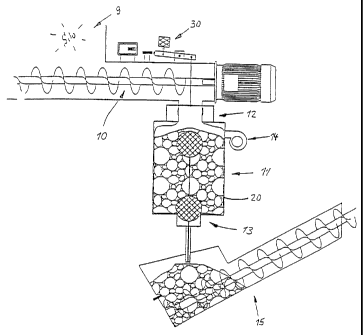
Figure 1 illustrates an embodiment of a removal device as
claimed for the invention in a first operating state,
Figure 2 the removal device as claimed for the invention in a
second operating state.
Figures 1 and 2 illustrate a delivery conveyor 10 in the
bottom of a silo 9. The conveyor 10 is powered by an electric
motor and delivers bulk material to the exterior from the interior
of the silo 9. The bulk material reaches a cylindrical container
2


CA 02246492 2004-05-12
23267-94
11 which may be sealed by a valve 12 at the top and a valve
13 at the bottom. Below the container 11 there is a
receptacle, and a conveyor mechanism 15 ensures delivery of
the feed removed to the feeding station proper.
The mode of operation of the device is as follows.
At the beginning of the emptying process the lower valve 13
is closed and the upper valve 12 open (Figure 1). In this
manner the feed moves from the silo 9 to the container 11.
The upper valve 12 is then closed and the lower valve 13
opened (Figure 2). Before the emptying process is repeated
the lower valve 13 is closed and the interior of the
container 11 evacuated through the opening 14. A new
emptying process, in which the upper valve 12 is opened, may
then be initiated.
In the interior of the container 11 there is a
cylindrical diaphragm 20 which is fastened at the top and
bottom of the container as required.
The mode of operation of the diaphragm is as
follows:
At the beginning of an emptying process material
is moved through the opened valve 12 into the interior of
the diaphragm 20 by the conveyor, the diaphragm ultimately
coming to rest against the wall of the container 11. The
upper valve 12 is then closed and the lower valve 13 open,
so that the material present in the interior of the
diaphragm 20 is discharged downward. This emptying process
may be promoted by compressed air introduced by way of the
opening 14. Figure 2 illustrates the diaphragm as emptied,
when it has collapsed onto itself and thus encloses zero
volume, in contrast to the charged state (Figure 1) in which
it rests tight against the inside wall of the container 11.
3


CA 02246492 1998-08-12
WO 97/29984 PCT/EP97/00614
The numeral 30 denotes a balance on which the container is
suspended so that the amount of feed removed may be weighed.
4

Representative Drawing
A single figure which represents the drawing illustrating the invention.
Administrative Status

For a clearer understanding of the status of the application/patent presented on this page, the site Disclaimer , as well as the definitions for Patent , Administrative Status , Maintenance Fee  and Payment History  should be consulted.

Administrative Status

Title Date
Forecasted Issue Date 2005-07-26
(86) PCT Filing Date 1997-02-11
(87) PCT Publication Date 1997-08-21
(85) National Entry 1998-08-12
Examination Requested 2002-02-06
(45) Issued 2005-07-26
Deemed Expired 2010-02-11

Abandonment History

There is no abandonment history.

Payment History

Fee Type Anniversary Year Due Date Amount Paid Paid Date
Application Fee $150.00 1998-08-12
Maintenance Fee - Application - New Act 2 1999-02-11 $50.00 1999-01-05
Maintenance Fee - Application - New Act 3 2000-02-11 $50.00 2000-02-10
Maintenance Fee - Application - New Act 4 2001-02-12 $50.00 2000-11-22
Request for Examination $400.00 2002-02-06
Maintenance Fee - Application - New Act 5 2002-02-11 $150.00 2002-02-08
Maintenance Fee - Application - New Act 6 2003-02-11 $150.00 2002-09-30
Maintenance Fee - Application - New Act 7 2004-02-11 $150.00 2003-10-23
Maintenance Fee - Application - New Act 8 2005-02-11 $200.00 2004-10-19
Final Fee $300.00 2005-05-02
Maintenance Fee - Patent - New Act 9 2006-02-13 $200.00 2005-09-30
Maintenance Fee - Patent - New Act 10 2007-02-12 $250.00 2006-10-05
Maintenance Fee - Patent - New Act 11 2008-02-11 $250.00 2007-10-11
Owners on Record

Note: Records showing the ownership history in alphabetical order.

Current Owners on Record
HAAKE, HINRICH
Past Owners on Record
None
Past Owners that do not appear in the "Owners on Record" listing will appear in other documentation within the application.
Documents

To view selected files, please enter reCAPTCHA code :


To view images, click a link in the Document Description column. To download the documents, select one or more checkboxes in the first column and then click the "Download Selected in PDF format (Zip Archive)" or the "Download Selected as Single PDF" button.

List of published and non-published patent-specific documents on the CPD .

If you have any difficulty accessing content, you can call the Client Service Centre at 1-866-997-1936 or send them an e-mail at CIPO Client Service Centre.


Document
Description 
Date
(yyyy-mm-dd) 
Number of pages   Size of Image (KB) 
Representative Drawing 1998-11-26 1 11
Cover Page 1998-11-26 1 44
Abstract 1998-08-12 1 9
Description 1998-08-12 4 129
Claims 1998-08-12 1 32
Drawings 1998-08-12 2 39
Description 2004-05-12 5 143
Claims 2004-05-12 2 43
Drawings 2004-05-12 2 39
Abstract 2004-11-09 1 9
Representative Drawing 2005-07-15 1 15
Cover Page 2005-07-15 1 43
Assignment 1998-08-12 2 92
Correspondence 2000-02-10 1 25
Correspondence 2000-11-22 1 25
Prosecution-Amendment 2002-02-06 1 47
Prosecution-Amendment 2002-03-14 1 43
Correspondence 2005-05-02 1 30
Fees 2002-02-08 1 36
Prosecution-Amendment 2004-04-05 2 62
Prosecution-Amendment 2004-05-12 8 224
Fees 2005-09-30 1 34
International Preliminary Examination Report 1998-08-12 17 594