Note: Descriptions are shown in the official language in which they were submitted.
' . CA 02246822 1998-09-04
s?2s-04 cwA
RAZOR WITH IN SITU SENSOR
Background of the Invention
0
1. Field ofthe Invention
This invention relates to the placement of one or more in situ sensors in razor heads,
cartridges, or handles to produce a movement or indication to aid in the quality of the shave.
s
2. Description of Related Art
Efforts to improve shave quality have been on-going for many years. Much of the
effort to improve shave quality has been directed toward making razor cartridges and blades
20 more responsive to the various forces encountered by the razor during shaving. Examples of
the results include razor systems having movable components7 such as blades, cartridges
which flex or bend in response to shaving forces and blades which move inward and
outward in response to those forces. One common thread b,-tween all previous shaving
systems with movable components is that the movements are produced by the function of a
2s mechanical element, such as a spring or pivot. Consequently, one limitation on the function
of all of these prior razor systems is that they are only as sensitive as their mechanical
elements.
It would be advantageous to provide a razor system which did not depend upon
30 mechanical elements for sensing the need for movement of the razor components but instead
depended upon a more sensitive medium, such as an electronic sensor, to signal that the
position of the razor cartridge or the cartridge itself needs cl-~nging. Accordingly, it is an
objective of the present invention to provide a razor system having cl~ nic sensors which
provide a signal which produces movement to adjust the position of the blades or produces
3s an indication to the user that l:he blades should be repositioned or replaced.
CA 02246822 1998-09-04
Summary of the Invention
The present invention is directed to a wet shave sha~ing system which contains an in
situ sensor within the razor ca~rtridge. The sensor preferably comprises either a piezoelectric
o or a pi_~olesistive material w~hich produces an electrical signal or resistance change when it
is strained. In an active feedback system, the signal would be transferred from the cartridge
to the razor handle where an e lectronically-activated actuatc~r would extend or retract as
necessary to position the blades to produce a shave with a constant shave force. In a passive
feedback system, the signal w ould be ll~~ ed from the c~rtridge to the razor handle
5 where an electronically-activated element, such as an indicator light, would be activated to
produce an indication to the user that he or she should reposition the razor to produce a
constant shave force. In an altemative embodiment of the passive feedback system, the
signal would provide an indication to the user that the blades are worn and should be
replaced.
Brief Description of the Drawings
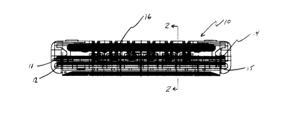
Figure 1 is a top view of a razor cartridge having an in situ sensor.
Figure 2 is a cut-away view through line 2-2 of the razor cartridge having an in situ
sensor.
Figure 3 is a front view of an altemative embodiment of a razor cartridge having an
in situ sensor.
Figure 4 is a cut-away view through line 4-4 of the razor cartridge having an in situ
sensor.
Figure 4A is a top view of razor handle and a cut-away view of a razor cartridge3s having an in situ sensor in the handle.
CA 02246822 1998-09-04
Figure 5 is top view of a razor handle and a cut-awa.y view of a razor cartridgehaving an actuator adapted to receive signals from an in situ sensor in a razor cartridge.
Figure 6a is a top view of a razor handle and canridge having an actuator in a
retracted position.
Figure 6b is a top view of a razor handle and cartridige having an actuator in an
unbiased position.
Figure 6c is a top view of a razor handle and cartridge having an actuator in ans extended position.
Figure 7 is a top view of a razor handle and cartrid~e having an indicator light.
Figure 8 is a top view of a razor hand~e and a cut-away view of a razor cartridge
having a sliding potentiometer.
Figure 9 is a top view of a razor handle and a cut-av~ay view of a razor cartridge
having a potentiometer.
Detailed Description of the Pl ~;Lled Embodiments
Reference will now be made to the presently preferred ernbodiments of the
invention. For the purpose ol this application, wet shave razors are defined to be razors
which are customarily utilized in conjunction with soap or shaving cream and hot water.
The definition of wet shave razors includes both disposable razors, in which the user
discards the entire unit after a certain number of uses, and perrnanent systems, with which
the user discards and replaces the razor canridge after a cenain number of uses. In both
instances, the razor head, or canridge, is the portion which surrounds and contains the blade
or blades. The combination of the razor head and the handle, either permanent ordisposable, is defined as the razor system.
CA 02246822 1998-09-04
The present invention provides for a wet shave razor head having one or more in situ
sensors which receive and produce a response to the forces encountered by the razor head
during shaving. The sensors are l~lcrelably constructed from either a piezoelectric or a
piezoresistive material which produce an electrical signal or resistance change when they are
o strained. A prefell~d piezoelectric polymer is polyvinylidene fluoride (PVDF) of the type
sold by Amp Inc., Valley Forge, Pennsylvania. PVDF is especially ple~e.lGd as a sensor
because it is very flexible and provides a good, strong electlical signal. In addition, PVDF
is commercially available in forms of various thickness which facilitates the proces~ing of
the material into a sensor which may be placed in virtually ~my location in a razor system.
5 One p.~r~l.ed form of the piezoelectric polyrner sensor is a film which is applied directly to
or close to the blades within the razor head. Preferred piezclresistive materials include
~,la~hile or pressure sensitive inks placed between mylar or another flexible, non-conductive
support, conductive foams and strain gauges consisting of a g id of fine wire or a constantan
metal foil grid encapsulated in a thin resin backing. These piezoresistive materials are all
20 capable of producing an electrical signal in response to forces encountered during shaving.
In an alternative embodiment, the sensor may comprise a potentiometer .
The in situ sensor may be placed in any desired location on the razor and Figures 1 -
4 illustrate presently pref~..G(l sensor locations. In addition, while the figures illustrate
25 cartridges having two blades, the in situ sensor may be utilized in a razor having one, two,
three or any other number of lblades. Figures I and 2 illustrate cartridge 10 having two
blades, I 1, 12. The in situ sensor, in the form of a piezoelectric polymer or piezoresistive
film 14, 15, is coated on a poltion of blades I I, 12 such thal: the film will be in a position to
detect the result of the forces encountered during shaving and to provide an electrical signal
30 b~ed on those forces. Among the various forces which normally will be encountered are
those which flex the cartridge upward or downward and those which produce stress and
strain on the blade or blades. Means for transmitting the electrical signal from the in situ
sensor to the receptor are also provided within the razor head. Preferably, such transmitting
means comprise a conductive material, such ~ wire 18, whi ch receives the electrical signal
35 or signals from the sensor or sensors and then transmits the signals through the razor head to
one or more receptors, which are preferably located within the razor handle.
CA 02246822 1998-09-04
An alternative in situ sensor site is illustrated in Figures 3 and 4. In this
embodiment, the in situ sensor is in the form of a solid piece of a piezoelectric or
piezoresisbive material 23, preferably PVDF or a composite thereof, which is located
between the two blades 21, 2,~. The sensor acts as a spacer to hold the two blades away
I o from each other and at the sarne time detects the result of forces encountered during shaving.
The location of the sensor in this embodiment is particularly useful for detecbing forces
acting on the razor head. The sensor generat¢s an electrical signal from the forces
transmitted through transmitb~ng means 24 to one or more receptors which are preferably
located within the razor hand] e.
s
In a further alternative embodiment, the sensor may be positioned within the razor
handle. In this embodiment, ~the sensor would indirectly measure the forces on the blade or
blades which are transferred to the handle. A pre~l led embodiment of this alternative
illustrated in Figure 4A employs a piezoresistive or piezoelectric sen~or 51 which is placed
in the handle 30. A movable piston 50 is placed in contact with the razor cartridge 52 or
blades and translates the forces encountered during shaving to the sensor.
Figure 5 illustrates the razor handle 30 of the present invention. The handle, in this
case illustrated as a permanen,t system with a replaceable cartridge, comprises ~tt~cl~m~ t
2s means 32 for the attachment of the razor cartridge, piston 31, conductor 34 and a receptor
which is illustrated in Figure 5 in the form of electric motor 38. Upon the placement of a
razor head on the handle, either permanently or replaceably. conductor 34 is connected to
the ~ llilling means of the razor head to form a circuit and receive the in situ sensor
signal through the transmitting means. For disposable razors, the ll~lslllilling means of the
razor head and the conductor may be a single unit. For perrnanent systems, the connection
is accomplished by placing connectors on the exposed ends of the tr~n~mitting means and
the conductor so that they attach to each other upon the plac ement of a razor head on the
handle. As with the transmitting means of the razor head, the conductor may be constructed
from any suitable conductive material, such as copper wire.
CA 02246822 1998-09-04
s Two different pr~r~lled embodiments of receptors exist for receiving and processing
the in situ sensor signal and one or more receptors may be employed in each prefe.led
embodiment. The first receptor embodiment is an active system in which the receptor is in
the form of a simple signal processing circuit which processes the in situ sensor signal and
produces a response to move and position the blades. In the preferred embodiment, the
lo receptor is a signal processing circuit in conjunction with an actuator which is used to move
and position the piston 31. While the actuator may be any rneans for sufficiently moving
the piston, as illustrated the actuator is preferably lead screw 36 which is driven by electric
motor 38 in series with coupling device 37. The piston 31 or a portion of the piston is
threaded and rides along the lead screw as the motor respon,ds to the feedback signal
generated by the signal proce:,sing circuit in response to the in situ sensor. Conductor 34
transmits the electrical signal from the in situ sensor to the signal processing circuit to
complete the electrical circuit. Based on the motor's respon,se to the in situ sensor signal,
lead screw 36 rotates and piston 31 correspondingly extends and retracts as necessary to flex
the razor head to position the razor head to p3l0duce a consistent shave. As illustrated in
Figures 6a, 6b and 6c, the expansion of the piston 31 will flex the razor head 35 into a
convex shape while the retraction of the piston will flex the razor head into a concave shape.
The second preferred receptor embodiment, illustrat,-d in Figure 7, is a passive2s system. In this embodiment one or more sensors, conductors and transmitting means
between the razor head and th,e handle may be as in the pre~ ious embodiment. In this
ennbodiment, the receptor in handle 40 does not produce motion but instead is a signal
processing circuit which activates an indicator, such as lighl 41. The receptor in the passive
systenn may also activate a light emitting diode (LED) or any other desired indicator. The
signal processing circuit receives the electrical signal from the in situ sensors and activates
an indicator, such as a light, which provides the user with a visual signal that he or she
should take some action. For example, the in situ sensor may be used to differentiate that
the user is exerting too much or too little p~e~iUle during shaving by generating a
comparable electrical signal t]hat would produce a visual ind~ication to the user to change the
3s shaving l)leS:;ul'e. In addition, because blades dull over time and thus require more pressure
to cut hair, the evolution of additional shavinx pressure ma~ be used to indicate that either
.. . , ~ , , , , .. .. " ... . .
CA 02246822 1998-09-04
s the disposable razor should be discarded or, in a permanent system, that the razor head
should be replaced. In an alternative embodiment, the voltage may be used to activate a
device such as a motor or piezoelectric transducer to produce a motion, such as a vibration,
or to activate an electric circuit on a circuit board or solid state chip which produces an
audible sound, such as notes of a song and/or a human-like voice. In a further alternative
0 embodiment, the passive systenn may be combined with the active system. For example, the
receptor may activate an actuator to produce a constant shave pressure while at the same
time lighting an indicator to indicate that the blades are worn and need replacing.
Further altermative embodiments of an in situ sensor comprising a potentiometer are
s illustrated in Figures 8 and 9. The potentiometer detects changes in the forces applied to the
blades upon transfer to the potentiometer shaft. Movement of the potentiometer shaft via a
translation, as in a sliding potentiometer, or rotation, as in a potentiometer, results in a
change in resistance indicative of the forces applied to the blades. Changes in resistance
may be converted into an equivalent voltage change and utilized to activate a device. In the
20 embodiment of Figure 8, sliding potentiometer 60 is located~ in handle 30. Potentiometer
shaft 61 of the sliding potentiometer receives forces from the blades through the shaving
cartridge 63 via piston 62. The change in resistance resulting from the movement of the
potemtiometer shaft along the sliding potentiometer may be converted into an equivalent
voltage change and utili~ed to activate an actuator or indical:or or some other device which
2s will movably respond or produce a visual indication to the user. In the embodiment of
Figure 9, a potentiometer 70 is located in handle 30. Forces encountered during shaving are
translated via piston 73 to lever 72 and then onto potentiometer shaft 71. As with the
previous embodiment, the translation of the forces will cause the potentiometer to produce a
resistance change which may be converted to an equivalent voltage and utilized to activate
30 an actuator or visual indicator in response to the applied shaving forces. In an alternative
embodiment, a combination of receptors may be employed such that either multiple active
responses are produced, multiple passive responses are prod~uced, or a combination of active
and passive responses are produced.
3s While there have been described what are presently believed to be the pr~ ed
embodiments of the present invention, those skilled in the art will realize that various
.~ ",, ,. . ,., . . .. . .. . . . . , ., , ~ . ~.. . . .. .. . . .
. CA 02246822 1998-09-04
5 changes and modifications may be made to the invention without departing from the spirit
of the invention, and it is intended to claim all such changes and modifications as fall within
the scope of the invention.