Note: Descriptions are shown in the official language in which they were submitted.
CA 02246827 1998-09-04
Sodium Secondary Battery
BACKGROUND OF THE INVEIJTION
Field of the Invention
The present invention relates to a sodium secondary
battery which is sealed in an improved manner, and in
particular to a rechargeable secondary battery applied to
batteries for storage of electric power for road grading and
to electric vehicles.
Background Art
FIG. 9 (PRIOR ART) is a schematic illustration of a
conventional sodium secondary battery.
As shown in FIG. 9, in the conventional sodium
secondary battery, a negative electrode chamber is formed by
placing sodium 3 into a bottom-closed, hollow cylindrical
solid electrolyte 2 provided inside an outer case 1; and
between the outer case 1 and the solid electrolyte 2 is
disposed a porous electrode 4 impregnated with sulfur 5
serving as a positive electrode active substance, to thereby
form a positive electrode chamber. An outer case metal
fitting 6 having an L-shaped cross section is welded to the
opening portion of the outer case 1. Fc>r a cover 12, a
metal fitting (hereinafter referred to ;~s a cover metal
fitting 8) is provided. An electric insulator 7, attached
along the outer periphery of the solid .=lectrolyte 2 in the
vicinity of its opening, is sandwiched between the outer
case metal fitting 6 and the cover meta:L fitting 8 via an
1
CA 02246827 1998-09-04
aluminum alloy 9 serving as a brazing material, and
undergoes hot-pressing to thereby provide sealing of the
structure.
With the above structure, in the discharge process the
sodium 3 contained in the negative electrode chamber
dissociates into sodium ions and electrons. The sodium ions
pass through the solid electrolyte 2 tc migrate into the
positive electrode chamber outside the solid electrolyte and
are combined with t:he sulfur 5 and electrons circulating
outside the cell to thereby form sodium. polysulfide.
Meanwhile, in the charge process, sodium polysulfide
present in the positive electrode chamber dissociates into
sodium ions, electrons, and sulfur. Th~~ formed sodium ions
pass through the solid electrolyte 2 to migrate into the
negative electrode chamber defined by the inside of the
tubular solid electrolyte and are combined with electrons
circulating outside the cell to thereby form sodium 3.
The process for manufacturing the above cell will next
be described.
(1) The insulator 7 is bonded to the upper portion of the
bottom-closed, tubular solid electrolyte 2 by use of a glass
solder 10.
(2) The upper face of the insulator 7 is bonded to the
cover metal fitting 8, and the lower part of the insulator 7
is bonded to the outer case metal fitting 6, both by hot-
press bonding by the mediation of aluminum alloy 9 serving
as a brazing material. As used herein, the term "hot-press
2
CA 02246827 1998-09-04
bonding" refers to bonding between heterogeneous materials
by the application of pressure in an atmosphere of about
600°C, which is close to the melting po:_nt of aluminum alloy
9.
(3) The positive electrode 4 impregnated with the sulfur 5
serving as a positive electrode active substance is placed
in the outer case 1, and then the outer case metal fitting 6
is welded to the outer case 1.
(4) A wick 11, which also serves as a :>afety tube and has a
sodium discharge outlet 11a, is secured onto the cover 12,
which is then welded with the cover metal fitting 8.
(5) The sodium 3, in the form of liquid, is injected from a
sodium-injection-hole, and the hole is ;pealed with a sealing
member 13.
Problems that arise in relation to hot-press bonding
for manufacturing the sodium secondary battery will next be
described.
(1) A high temperature is required for melting the aluminum
alloy 9 serving as a brazing material; i~hus, a heating
apparatus, such as an electric furnace achieving a
temperature as high as approximately 600°C, is required. A
vacuum condition may also be required, <depending on the
bonding method employed.
(2) Under the aforementioned conditions (i.e., high
temperature and in ~,racuo), pressurization must be performed,
which raises disadvantages associated w:'~th scaling up of the
apparatus employed <~nd an increase in the number of
3
CA 02246827 1998-09-04
manufacturing steps, such as cooling from high temperatures
and raising pressure from the vacuum condition to
atmospheric pressure.
(3) There may be a case in which (3-alumina, serving as an
insulator, breaks due to high temperature. The breakage
induces reaction between sodium and sulfur to suddenly cause
a high temperature condition. When the temperature is
higher than the melting point of aluminium, the cell is
broken.
(4) Conventional planar-type sodium secondary batteries
suffer a problem of poor sealing caused by a large
proportion of hot-press-welded parts since flanges located
at the periphery of a positive electrodf~ container and a
negative electrode container being opposite to each other
are hot-press welded.
SUMMARY OF THE INVENT=CON
The present invention was accomplished in order to
solve the problems .remaining in the con~rentional techniques,
and an object of the present invention ._s to provide a
rechargeable secondary battery applied t=o batteries for
storage of electric power for road-grad=_ng and to electric
vehicles.
To solve the above-described problE~ms, in a first
aspect of the present invention, there is provided a sodium
secondary battery in which a negative e~_ectrode chamber is
formed inside a bottom-closed, hollow cylindrical, solid
4
CA 02246827 1998-09-04
electrolyte, which is accommodated in an outer case, and a
positive electrode chamber is formed outside the solid
electrolyte, wherein a cover which closes the opening of the
outer case is fastened to the outer case by bolts and the
interposition of an insulator.
According to the first aspect of the invention, the
following four advantages are obtained, since the cover,
which closes the opening of the outer c,~se, is sealed by the
bolts and the interposition of an insul:~tor.
i) A secondary battery can be manufactured without thermal
stress being generated and with remarkably increased yield;
ii) An electric furnace is eliminated from the manufacturing
facility, whereby the time for heating :in the electric
furnace is saved, a cooling step may be omitted, manufacture
is simplified, and the facility cost is reduced remarkably.
iii) Since the solid electrolyte 2 will not be broken,
possibility of disintegration of the brazed members is
reduced even when the temperature of the brazed portion
becomes higher than the melting point oi_ aluminum as a
result of reaction between sodium and sulfur; and
iv) The battery is easily disassembled by simple loosening
of the bolts, to thereby facilitate recycling the battery,
which is more difficult in the case of batteries fabricated
through melt bonding.
In the above-described first aspect: of the invention,
preferably, the cover and the opening portion of the outer
case of the sodium secondary battery arE~ formed of a common
CA 02246827 1998-09-04
material and the linear expansion coefficient thereof is
greater than that of the insulator. This is advantageous in
that more secure fastening with bolts is achieved to thereby
provide improved sealing.
Preferably, a space is provided, at the opening
portion of the outer case, to allow expansion of the bolts
when the cell temperature rises to the operation temperature
of the battery. This structure is advantageous in that need
for washers is eliminated.
Preferably, the insulator also serves as a cover. With
the employment of an insulator which also functions as a
cover, the number of members is reduced to thereby simplify
the structure of the casing. PreferablSl, the flanges are
formed such that their bolt-receiving portions have an
increased thickness to accommodate the expansion of the
bolts when the cell temperature rises t~ the operation
temperature of the battery. With this ;structure, use of
washers is advantageously eliminated.
In a second aspect of the present invention, there is
provided a sodium secondary battery in which a positive
electrode chamber is formed inside a bottom-closed, hollow
cylindrical, solid electrolyte, which is accommodated in an
outer case, and a negative electrode chamber is formed
outside the solid electrolyte, wherein a cover which closes
the opening of the outer case is fastened to the outer case
by bolts and the interposition of an insulator.
The second aspect of the invention permits manufacture
6
CA 02246827 1998-09-04
of a sodium secondary battery, in which a positive electrode
chamber is formed inside and a negative electrode chamber is
formed outside without thermal stress being generated;
remarkably increases yield; and eliminates the use of an
electric furnace in the manufacturing process, whereby the
time for heating in the electric furnace is saved, a cooling
step may be omitted, manufacture is simplified, and the
facility cost is reduced remarkably.
Preferably, the insulator according to the second
aspect of the invention also serves as ~~ cover. With the
employment of an insulator, which also :Functions as a cover,
the number of members is reduced to the:_eby simplify the
structure of the casing.
In the third aspect of the present invention, a sodium
secondary battery, in which a negative Electrode chamber on
one side is separated from a positive electrode chamber on
the other side via a plate-like solid e:Lectrolyte, is
provided; and a neg<~tive electrode container having an
outwardly projecting flange and a posit:we electrode
container having another outwardly projEacting flange are
located opposite to each other; wherein an insulator is
provided along the periphery of the sol:_d electrolyte, and
the flange of the negative electrode container and the
flange of the positive electrode chamber: are fastened to
each other by bolts and the~interpositian of the insulator
therebetween.
With this structure according to the third aspect of
7
CA 02246827 1998-09-04
the invention, the flanges can be fastened by the sole use
of the bolts and, therefore, the level of sealing can be
arbitrarily tuned by adjusting intervals between the bolts
in the flanges, in contrast to the case of conventional
plate-type sodium secondary batteries, which suffer problems
attributed to poor sealing due to an enlarged area in which
hot press bonding is performed relative to the area in which
reaction of the solid electrolyte of th? cell occurs. In
this preferred feature of the present i:zvention, more
preferably, the cover and the opening p~~rtion of the outer
case of the sodium secondary battery ar~=_ formed of a common
material and the linear expansion coefficient thereof is
greater than that of the insulator. This achieves more
secure fastening with the bolts, to the:_eby provide improved
sealing. Preferably, the flanges are formed such that their
bolt-receiving portions have an increasE~d thickness to
ensure the effect of tight fastening ati~ributed to the
difference in expansion between each bo:Lt and its
surrounding parts when the cell temperai:ure rises to the
operation temperature of the battery. pith this structure,
use of washers is advantageously elimin~~ted.
BRIEF DESCRIPTION OF THE DRAWINGS
The present invention will become more fully
understood from the detailed description given hereinbelow
and the accompanying drawings which are given by way of
illustration only, and these are not imitation of the
8
CA 02246827 1998-09-04
present invention, and wherein:
FIGS. 1A and 1B depict a schematic illustration of a
secondary battery according to a first embodiment of the
present invention;
FIG. 2 is an enlarged illustration of a fastening
portion of the battery shown in Fig. 1;
FIG. 3 is a schematic illustration of a secondary
battery according to a second embodimenv of the present
invention;
FIG. 4 is a partial, enlarged illu~~tration of the
fastening portion of the battery shown un Fig. 3;
FIG. 5 is a perspective view of th~~ secondary battery
according to the second embodiment of tree present invention;
FIG. 6 is a plan view of the secondary battery
according to the second embodiment of the present invention;
FIG. 7 is a schematic illustration of a secondary
battery according to a third embodiment of the present
invention;
FIG. 8 is a schematic illustration of a secondary
battery according to a fourth embodiment: of the present
invention; and
FIG. 9 is a schematic illustration of a conventional
secondary battery.
DETAILED DESCRIPTION OF THE INVENTION
AND PREFERRED EMBODIMENTS
The present invention will next be described with
9
CA 02246827 1998-09-04
reference to specific embodiments, which should not be
construed as limiting the invention.
(Embodiment 1)
FIG. 1A and FIG. 1B are a schematic illustration of a
sodium secondary battery according to a first embodiment of
the present invention.
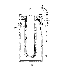
As shown in FIG. 1A and FIG. 1B, t:he sodium secondary
battery, according to the first embodiment of the present
invention, has a structure the same per se as that of the
conventional secondary battery, as shown in Fig. 9, but has
an outer case sealed with a cover in a different manner to
provide improved sealing of the battery..
The sodium secondary battery, acco:_ding to the first
embodiment of the present invention, has a negative
electrode chamber formed by placing sod~.um 3 into a bottom-
closed, hollow cylindrical solid electrolyte 2 provided
inside an outer case 1. A positive electrode chamber, which
houses a porous electrode 4 impregnated with sulfur 5,
serving as a positive electrode active ~>ubstance is provided,
between the outer case 1 and the solid electrolyte 2. A
cover 22, which clo:>es an outer case metal fitting 21
provided for the opening portion of the outer case 1, is
fastened by bolts 2~E with the interposition of an insulator
23. Parts in FIG. 1A and FIG. 1B corresponding to the same
parts shown in FIG. 9 are labeled with the same numerals,
which are used without definitions, since the sodium
secondary battery shown in FIG. 9 and that shown in FIG. 1A
CA 02246827 1998-09-04
and FIG. 1B are basically identical to each other with the
exception of the fastening structure for the cover.
Specifically, according to this embodiment, the cover
22 is fastened with the insulator 23 and the outer case
metal fitting 21 by exclusive use of bolts 24. In this case,
the thickness and linear expansion coefficient of each
member are adjusted to maintain improve~~ sealing of the
battery even during operation at high temperature.
The outer case metal fitting 21 is provided along the
periphery of the opening of the outer c;~se 1 to be united
therewith by welding; is formed of the same material as the
cover 22; and has a linear expansion coE~fficient different
from that of the insulator 23.
FIG. 2 is an enlarged illustration of a fastening
portion of the above structure.
As shown in FIG. 2, the insulator :?3 is bonded on its
lower side with the outer case metal fitting 21 and on its
upper side with the bolt 24, via aluminlun packings 25a and
25b, respectively. A space 26 and a space 27 are provided
between the bolt 24 and each of the covE~r 22, the insulator
23, and the outer case metal fitting 21.
The space 26 is provided so that the bolt 24 made of
metal and the insulator 23 made of, for example, a-alumina,
do not interfere wit=h each other, which would otherwise
occur, for example, in such a case where the two members
having different expansion coefficients expand differently
due to the material difference. The space 27, provided
11
CA 02246827 1998-09-04
between each of the cover 22 and the outer case metal
fitting 21 and the bolt 24, is provided to ensure the effect
attributed to the difference in linear expansion coefficient
between the bolt 24 and the cover 22 or metal fitting 21,
when the cell temperature rises as high as the operation
temperature of the :battery (e. g., about 320°C).
In fastening by the bolts, the bolt 24 is tightened
making use of difference in linear expansion coefficients of
the materials and the accompanying difference in expansion
generated during th~a temperature change from ambient
temperature to high temperature; thus, only insulating
washers 28 are required, eliminating them necessity of
generally-used washers which compensate expansion of bolts.
The material, length or thickness, and linear
expansion coefficient of each material used in the present
embodiment are shown in the following T~~ble 1.
Table 1
Length, Linear expansion coeff.
Material thickness
(1)~C
[mm]
Bolt SCM 435 1B = 23
(11-12) x10-6
Cover SUS 304 if = 3
(17-18) x10-6
Packing A1 1p = 1 (2?-24) x10-6
Insulator oc-alumina la = 10 ( 7 . 5-8 . 5 ) x10-6
Packing A1 1p = 1 (23-24) x10-6
Outer case
metal SUS 304 15 = 10
(17-18) x10-6
fitting
Linear expansion from ambient tempEarature (20°C) to the
operation temperature (320°C) of the bolt and that of the
surrounding parts are determined for the materials shown in
12
CA 02246827 1998-09-04
Table 1.
(1) Expansion of the bolt 24 = 23 x 11.5 x 10-6 x (320-20) -
0.0794 [mm]
(2) Expansion of {cover (22), packing (25a), insulator (a-
alumina) (23), packing (25b), outer case metal fitting (21)}
- { 3 x 17 . 5 x 10⁻⁶ + 1 x 2 3 . 5 x 10⁻⁶ + 10 x 8 . 0 x 10-6 + 1 x
23.5 x 10-6 + 10 x 17.5 x 10-°} x (320-20) - 0.1064 [mm]
The results show that the expansion of (2) is greater
than the expansion of (1), indicating t:zat the bolt is
tightened as the temperature rises from ambient temperature
to the operation temperature, to thereb:~ provide improved
sealing.
Specifically, selection of materials which satisfy the
relationship, [expa:nsion of the bolt]<_[f~xpansion of the
cover + expansion of the insulator (a-a:Lumina) + expansion
of the outer case metal fitting + expansion of the aluminum
packings], enables excellent sealing of the battery to be
maintained at high temperature during o~~eration.
Fastening of the present embodiment/ provides the
following advantages as compared with that achieved by a
conventional technique.
i) A secondary battery can be manufactured without thermal
stress being generated and with remarkably increased yield.
ii) An electric furnace is eliminated from the manufacturing
facility, whereby the time for heating ._n the electric
furnace is saved, a cooling step may be omitted, manufacture
is simplified, and the facility cost is reduced remarkably.
13
CA 02246827 1998-09-04
iii) Since the solid electrolyte 2 will not be broken,
possibility of disintegration of the bonded members is
reduced even if the temperature of the bonded portion
becomes higher than the melting point of aluminum as a
result of reaction between sodium and sulfur; and
iv) The battery is easily disassembled ~y simply loosening
the bolts, to thereby facilitate recycling of the battery,
which is more difficult in the case of batteries fabricated
through melt bonding.
(Embodiment 2)
FIG. 3 is a schematic illustration of a plate-type
sodium secondary battery according to a second embodiment of
the present invention.
As shown in FIG. 3, the sodium secondary battery,
according to the second embodiment of the present invention,
includes a negative electrode chamber in which sodium 31 is
placed, a positive Electrode chamber wh=_ch houses a porous
electrode 32 impregnated with sulfur 33, and a plate-like
solid electrolyte 3c) interposed therebet:ween. The negative
electrode chamber is defined by a negative electrode
container 35 having an outwardly projecting flange 34 and
the positive electrode chamber is defined by a positive
electrode container 37 having an outwardly projecting flange
36, and the negatlVE' and positive electrode containers 35
and 37 are located opposite to each other with respect to
the solid electrolyte 30. An insulator 38 is provided along
the periphery of the solid electrolyte L',0, and the outwardly
14
CA 02246827 1998-09-04
projecting flange 34 of the negative electrode and the
outwardly projecting flange 35 of the p~~sitive electrode
chamber are fastened by bolts 39a and nuts 39b. In FIG. 3,
numeral 40 indicates a wick which also .serves as a safety
tube.
In the second embodiment, the outwardly projecting
flange 34 of the negative electrode, thf~ insulator 38, and
the outwardly proje~~ting flange 35 of the positive electrode
are fastened by use of only bolts 39a and nuts 39b. In this
case, the thickness and linear expansion coefficient of each
member are adjusted to maintain improved sealing of the
battery even during operation at high temperature.
In the second embodiment, the outwardly projecting
flange 34 of the negative electrode and the outwardly
projecting flange 3c~ of the positive electrode are formed of
a common material and have a linear expansion coefficient
different from that of the insulator 38.
FIG. 4 is an enlarged illustration of a fastening
portion of the above structure.
As shown in FICJ. 4, the insulator 38 is secured on one
side to the outwardly projecting flange 34 of the negative
electrode and on the other side to the outwardly projecting
flange 36 of the po:>itive electrode by the bolt 39a and the
nut 39b and via an aluminum packing 41a and an aluminum
packing 41b. A space 42 and a space 43 are provided between
the bolt 39a and each of the outwardly projecting flange 34
of the negative electrode, the outwardly projecting flange
CA 02246827 1998-09-04
36 of the positive electrode, and the insulator 38.
The space 42 is provided so that the bolt 39a made of
metal and the insulator 39 made of, for example, a-alumina,
do not interfere with each other, which would otherwise
occur, for example, in such a case where the two members
having different expansion coefficients expand differently
due to the material difference. The space 43, provided
between the bolt 39a and each of the ouvwardly projecting
flange 34 for the n~agative electrode anti the outwardly
projecting flange 36 for the positive e:Lectrode, ensures the
effect of tight fastening owing to the difference in linear
expansion coefficient between the bolt 39a and its
surrounding parts even under high temperature conditions.
As shown in th~~ perspective view o:E FIG. 5, in the
present embodiment, the outwardly projecting flange 34 of
the negative electrode and the outwardly projecting flange
36 of the positive electrode are thicker. than flanges 34a
and 36a defining they remaining portions of peripherally-
provided flanges to ensure the effect o1. tight fastening
attributed to the d_~fference in linear expansion coefficient
between each bolt and its surrounding parts and the
accompanying difference in expansion generated when the cell
temperature rises to the operation temperature of the
battery. FIG. 6 is a plan view of a plate-type sodium
secondary battery.
In fastening bar the bolts, only inoculating washers 44
are used, thereby eliminating the neces~~ity of generally-
16
CA 02246827 1998-09-04
used washers which compensate expansion of bolts.
The material, length or thickness, and linear
expansion coefficient of each material used in the present
embodiment are shown in the following Table 2.
Table 2
Length, Li:zear expansion coeff.
Materiel thickness
(1~~C
fmm]
Bolt SCM 435 1B = 30 -6
(11-12) x10
Negative
electrode SUS 309 is = 10
(1'7-18) x10-6
flange
Packing A1 1p = 1 ( 2:3-24 ) x10-6
Insulator oc-alumi.na 1a = 10 (7 .5-8 . 5) x10'6
Packing A1 1p = 1 (2:3-24) x10-6
Positive
electrode SUS 309 is = 10
( 1'7-18 ) x10-6
flange
Linear expansion from ambient temperature (20°C) to the
operation temperature (320°C) of the bolt and that of the
surrounding parts are determined for thf~ materials shown in
Table 2.
(1) Expansion of th~~ bolt (39) - 30 x 1:L.5 x 10-6 x (320-20)
- 0.1035 [mm]
(2) Expansion of {positive electrode flange (thick portion)
(34), aluminum pac king (41a), insulator (a-alumina) (38),
aluminum packing (41b), positive electrode flange (thick
portion) (36) } - {10 x 18 x 10-6 + 1 x 2:3.5 x 10⁻⁶ + 10 x 7.4
x 10-° + 1 x 23.5 x LO-6 + 10 x 18 x 10-6} x (320-20) - 0.1443
[mm]
The results show that the expansion of (2) is greater
than the expansion of (1), indicating that the bolt is
17
CA 02246827 1998-09-04
tightened as the temperature rises from ambient temperature
to the operation temperature, to thereby provide improved
sealing.
Thus, selection of materials which satisfy the
relationship, [expansion of the bolt)<_[expansion of the
negative electrode flange + expansion of the insulator (a-
alumina) + expansion of the positive el?ctrode flange +
expansion of the aluminum packing], enables excellent
sealing of the battery to be maintained at high temperature
during operation.
In addition to the previously-described advantages i)
to iv) acknowledged in relation to the ~~ase of the hollow-
cylindrical type battery, fastening of -she second embodiment
further provides this following advantagE~s as compared with
that by a conventional technique:
v) The flanges can be fastened by use o:~ only bolts and nuts,
and therefore, can be arbitrarily tuned by adjusting
intervals between bolts in the flanges, in contrast to the
case of conventiona:L plate-type sodium secondary batteries,
which suffer problems attributed to poor sealing due to an
enlarged area in which hot press bondin<~ is performed
relative to the area in which reaction of the solid
electrolyte of the cell occurs.
( Embodiment 3 ~
FIG. 7 is a schematic illustration of a sodium
secondary battery a<:cording to a third embodiment of the
present invention.
18
CA 02246827 1998-09-04
As shown in FIG. 7, the sodium secondary battery,
according to the third embodiment, has a battery structure
the same per se as that shown in FIG. 1A and FIG. 1B, but
provides improved sealing due to the employment of a
different fastening manner of a cover and a case. Briefly,
an outer case 1 is fastened to a cover 22 by bolts and nuts,
with the bolts being arranged so as not to penetrate an
insulator, to thereby provide improved .sealing.
The sodium secondary battery according to the third
embodiment has a negative electrode chamber formed by
placing sodium 3 into a bottom-closed, hollow cylindrical
solid electrolyte 2 provided inside an cuter case 1. A
positive electrode chamber, which house: a porous electrode
4 impregnated with ;sulfur 5 serving as a positive electrode
active substance is provided between thE= outer case 1 and
the solid electrolyw~e 2. A cover 22 is fastened to an outer
case flange 50, provided along the periphery of the opening
of the case, by the bolts 51 and nuts 52 and the
interposition of an insulator 23. Parts in FIG. 1A and FIG.
1B corresponding to the same parts shown in FIG. 7 are
labeled with the same numerals, which are used without
definitions, since t=he sodium secondary battery shown in FIG.
7 and that shown in FIG. 1A and FIG. 1B are basically
identical to each other with the exception of the sealing
structure for the cover.
Specifically, according to the third embodiment,
unification of the cover 22, the insulator 23, and the outer
19
CA 02246827 1998-09-04
case flange 50 is conducted by the bolts 50 and nuts 51.
This embodiment differs from the case of the first
embodiment in that fastening of the cover is performed
without penetration of the bolts throug:z the insulator 23.
When fastening is performed, aluminum packings 53a and 53b
are used, and the thickness and linear ~=_xpansion coefficient
of each member are adjusted to maintain improved sealing of
the battery even during operation at high temperature.
In the third embodiment, the outer case flange 50 is
integrally provided at the opening of the outer case 1 by
welding; is formed of the same material as the cover 22; and
has a linear expansion coefficient diffE~rent from that of
the insulator 23.
In fastening by the bolts 51 and nuts 52, the bolts 51
are tightened by making use of difference in the linear
expansion coefficients of the materials and the accompanying
difference in expansion generated durin<~ the temperature
change from ambient temperature to high temperature; thus,
only insulating washers 54a and 54b are used and generally-
used washers which compensate expansion of bolts are not
required.
The material, :Length or thickness, and linear
expansion coefficient of each material used in the third
embodiment are shown in the following T<<ble 3.
CA 02246827 1998-09-04
Table 3
Length, Linear expansion coeff.
Material thickness
[mml (l;~ /C
Bolt SCM 435 1H = 18 -6
(1:L-12) x10
Cover SUS 304 if = 3 ( 1'7-18 ) x10-6
Packing A1 l~ = 1 (23-24) x10-6
Insulator a-alumina la = 10 (7 , 5-8 . 5) x10-6
Packing Al 1P = 1 ( 2:3-2 4 ) x 10-6
Outer case SUS 304 15 = 3 ( 1'~-18 j x10-6
flange
Linear expansion from ambient temperature (20°C) to the
operation temperature (320°C) of the bolt and that of the
surrounding parts a:re determined for the' materials shown in
Table 3.
(1) Expansion of the bolt (51) - 18 x 1._.5 x 10-5 x (320-20)
- 0.0621 [mm]
(2) Expansion of {cower (22) , packing (53a) , insulator (a,-
alumina) (23), packing (53b), outer case flange (50)} - {3 x
17 . 5 x 10⁻⁶ + 1 x 2 3 . 5 x 10⁻⁵ + 10 x 8 . 0 :~ 10-' + 1 x 2 3 . 5 x
10-G + 3 x 17.5 x 10~~6} x (320-20) - 0.0696 [mm]
The results show that the expansion of (2) is greater
than the expansion of (1), indicating that the bolts are
tightened as the temperature rises from ambient temperature
to the operation ternperature, to thereb~~ provide improved
sealing.
Specifically, selection of materia=_s which satisfy the
relationship, [expansion of the bolt]<_[expansion of the
cover + expansion oi_' the insulator (cc-al.umina) + expansion
of the outer case f7_ange + expansion of the aluminum
21
CA 02246827 1998-09-04
packings]; enables excellent sealing of the battery to be
maintained at high temperature during operation.
In addition to the advantages obtained from the first
embodiment, fastening of the present embodiment further
provides the following advantage:
vi) Processing of t:he insulator is not necessary. Moreover,
processing of the outer case metal fitting 21, shown in FIG.
1A and FIG. 1B, to be adapted to fastening with bolts is not
necessary, and simp:Le bolt-and-nut fastE~ning provides high
level of sealing though use of a simplf~ structure.
(Embodiment 4 )
FIG. 8 is a schematic illustration of a sodium
secondary battery according to a fourth embodiment of the
present invention.
As shown in FIc.;. 8, the sodium secondary battery,
according to the fourth embodiment, difj'ers from the battery
of FIG. 7 in that, ._n the structure of t:he battery itself,
sulfur 5 is contained inside the tubular solid electrolyte 2
and sodium 3 is disposed outside the soJ_id electrolyte 2,
and in that use of t:he cover 22 is eliminated, with the
insulator 23 also serving as a cover.
The sodium secondary battery, according to the fourth
embodiment, has a positive electrode chamber formed by
placing sulfur 5 serving as a positive electrode active
substance into a bottomed-closed, hollow cylindrical solid
electrolyte 2, which is provided inside an outer case 1. A
negative electrode chamber containing sodium 3 is provided
22
CA 02246827 1998-09-04
between the outer case 1 and the solid electrolyte 2. An
insulator 23, which also serves as a cover for closing the
outer case 1 at its outer case flange 50 provided along the
periphery of the opening of the outer case l, is disposed to
cover the upper opening of the solid electrolyte 2 and
fastened by the bolts 51 and nuts 52. ::n FIG. 8, reference
numeral 56 indicates an electricity-collecting rod.
Thus, fastening of the outer case flange 50 of the
fourth embodiment to the insulator 23, v~hich also serves as
a cover, is performed by use of the bolts 50 and nuts 51.
This embodiment differs from the case of the first
embodiment in that the fastening is performed without
penetrating the insulator 23 and without need of a cover as
shown in FIG. 7.
When fastening is performed, an aluminum packing 53a
and metal washers 55 are used, and the thickness and linear
expansion coefficient of each member ar~~ adjusted to
maintain improved sealing of the battery even during
operation at high temperature.
In the fourth embodiment, the outer case flange 50 is
integrally provided at the opening of the outer case 1 by
welding, and has a linear expansion coe:Eficient different
from that of the insulator 23 which also serves as a cover.
In fastening by use of the bolts 51 and nuts 52, the
bolts 51 are tighte:zed by making use of difference in the
linear expansion coefficients of the maj~erials and the
accompanying differ~snce in expansion generated during the
23
CA 02246827 1998-09-04
temperature change from ambient temperature to high
temperature. Insul;~ting washers 54a and 54b and a metal
washer 55 provide further improved sealing.
The material, length or thickness, and linear
expansion coefficient of each material used in the fourth
embodiment are shown in the following Table 4.
Table 4
Length, Linear expansion coeff.
Material thickziess
Lmm] (l;~ /C
Bolt SCM 435 1g = 18 -6
(1:L-12) x10
Washer SUS 304 if = 3 (1'7-18) x10-6
Insulator a-alumina la = 10 (7 , 5-8.5) x10-6
Packing A1 1p = 1 (23-24 ) x10-6
Outer case SUS 304 is = 3 ( 1'I-18 ) x10-6
flange
Linear expansion from ambient temperature (20°C) to the
operation temperature (320°C) of the bolt and that of the
surrounding parts i:aclusive are determined for the materials
shown in Table 4.
(1) Expansion of the bolt (51) - 17 x l:'~.5 x 10-6 x (320-20)
- 0.05865 [mm]
(2) Expansion of {w~~sher (55) , insulator (a-alumina) (23) ,
packing (53), outer case flange (50)} - {3 x 17.5 x 10-E +
10x8.0x10-"+1 x23.5x10-6+3x17.5x10-6} x (320-
20) - 0.0626 [mm.]
The results sh~~w that the expansion of (2) is greater
than the expansion of (1), indicating that the bolts are
tightened as the temperature rises from ambient temperature
to the operation temperature, thereby pi:oviding an improved
24
CA 02246827 1998-09-04
sealing.
Briefly, selection of materials which satisfy the
relationship, [expansion of the bolt]<_[expansion of the
cover + expansion of the insulator (a-alumina) + expansion
of the outer case flange + expansion of the aluminum
packings], enables excellent sealing of the battery to be
maintained at high temperature during operation.
In addition tc the advantages obtained from the
previously described embodiments, sealing of the fourth
embodiment further provides the following advantage:
vii) The insulator; which also serves as a cover,
eliminates use of a cover. When the ce__1 temperature rises
during operation, excellent sealing can be obtained, since
metal washers 55 are provided for compensating expansion of
bolts 51.
In the above-described fourth embodiment, a sodium
secondary battery is constructed by forming a positive
electrode chamber inside a one-end-closed, tubular solid
electrolyte disposed inside the outer case and a negative
electrode chamber outside the solid ele~~trolyte, wherein the
insulator also serves as a cover. However, this embodiment
may be further modified; a sodium secondary battery having a
structure, as described with reference -~o Embodiment 1, can
also be constructed with the exception '.hat the insulator
material also serves as a cover.
The invention being thus described, it will be obvious
that the same may be varied in many ways. Such variations
CA 02246827 1998-09-04
are not to be regarded as a departure from the spirit and
scope of the invention, and all such mo~~ifications as would
be obvious to one skilled in the art arcs intended to be
included within the scope of the following claims.
26