Note: Descriptions are shown in the official language in which they were submitted.
CA 02246835 1998-09-08
REMOTE BRAKE APPLICATION VALVE
FIELD OF THE INVENTION
The present invention relates, in general, to remote
brakepipe exhaust valves and, more particularly, the instant
invention relates to a remote valve for emergency and service
exhaust of brakepipe air in a railway vehicle.
BACKGROUND OF THE INVENTION
In the conventional railroad braking system, which is
derived from the Westinghouse airbrake, brakes are controlled
by air pressure in a brake air line, brakepipe, which is
connected between individual railway vehicles in a consist of
coupled railway vehicles. Pressure in the brake air line is
generally controlled by a lead locomotive of the consist.
Fail-safe operation is provided by designing the system so that
the brake air line is pressurized to release the brakes, and
depressurized to apply brakes. Emergency braking is provided
by rapidly venting air from the brakepipe. If the brake air
line fails so that its pressure drops, brakes are automatically
applied.
Some time ie required for a pressure decrement, initiated
by the lead locomotive, to propagate down the line of railway
vehicles. A pressure decrement for a service brake application
requires about one minute to propagate down the length of a
mile-long freight train. A pressure decrement for an emergency
brake application requires about one half of a minute for a
mile-long train.
1
CA 02246835 1998-09-08
In order to provide more rapid application of brakes, for
either service or emergency application, an exhaust valve may
be provided in a portion of the train. It may be in a remote
locomotive of the train or in an end-of-train unit. The remote
unit or end of train unit is usually controlled by radio
signals from the locomotive, or it may be controlled by
electrical trainlines which are connected between the
individual railway vehicles of the train. The tramlines carry
electrical signals from the lead locomotive to the remote unit.
The exhaust valve has a control reservoir which, during
normal operation, contains air which is at the pressure of the
brake air line. A prior art valve has a piston in a cylinder
and has a diaphragm to prevent leakage between the piston and
the cylinder. The piston has air on one side which is at the
pressure of the brakepipe, and air on a second side which is at
the pressure of the control reservoir. The piston is connected
to a brakepipe exhaust valve which is closed when air on each
side of the piston is at the same pressure.
When the remote unit or end of train unit receives a
signal from the lead locomotive to exhaust air from the brake
air line, it vents air from the control reservoir. This causes
the piston to move and the brakepipe exhaust valve is opened.
The diaphragm has an annular fold which is directed toward
the second side of the piston to permit the piston to move,
while sealing between the piston and the cylinder. In normal
operation of the exhaust valve, the air pressure on the first
2
CA 02246835 1998-09-08
side of the piston is always equal to or greater than the air
pressure on the second side of the piston, so the annular fold
is able to withstand the pressure difference.
However, in a situation in which the brake air line fails
so that its pressure drops, and no signal is received by the
remote unit or end of train unit to reduce the pressure in the
control chamber, then the pressure on the second side of the
piston becomes greater than the pressure on the first side of
the piston. In this case, the annular fold of the diaphragm
may become jammed into the gap between the piston and the
cylinder. The system must then be serviced before it can be
used again.
SUMMARY OF THE INVENTION
The present invention is a valve system for exhausting air
pressure from a brakepipe in a remote portion of a train. Such
valve system includes pressure containment structure having a
cylindrical outer bore formed therein and a piston mounted for
axial movement in the cylindrical outer bore. A first valve
chamber is disposed on a first side of the piston and a second
valve chamber is disposed on a second side of the piston. A
diaphragm provides a seal between the piston and the
cylindrical outer bore, the diaphragm having an annular fold
for permitting relative axial movement of the piston within the
cylindrical outer bore. The annular fold is directed away from
the first valve chamber and toward the second valve chamber.
3
CA 02246835 1998-09-08
The valve system has a first brakekpipe pressure
passageway for conveying air from the brakepipe to the first
valve chamber and a control pressure connection for conveying
air from a control chamber to the second valve chamber. A
biasing means is provided in the second valve chamber for
urging the piston to move toward the first valve chamber.
A stem is connected to the piston and to a brakepipe
exhaust valve to be activated thereby. The brakepipe exhaust
valve being closed when the piston is moved toward the first
valve chamber and being opened when the piston is moved toward
the second valve chamber.
An exhaust chamber, which is connected to atmosphere, is
disposed on a first side of the brakepipe exhaust valve and a
brakepipe pressure chamber is disposed on a second side of the
brakepipe exhaust valve. The brakepipe pressure chamber having
a fluid connection to the brakepipe so that when the control
chamber is supplied with air at brakepipe pressure the
brakepipe exhaust valve is closed and so that when a control
pressure in the control chamber is reduced by venting to
atmosphere the brakepipe exhaust valve is opened and brakepipe
air is exhausted to atmosphere.
The pressure containment structure includes an annular
sleeve protruding into the fold of the diaphragm to prevent the
diaphragm from inverting if the pressure in the brakepipe drops
below the pressure in the control chamber when the piston is
positioned toward the first valve chamber.
4
CA 02246835 1998-09-08
OBJECTS OF TBE INVENTION
It is, therefore, one of the primary objects of the
present invention to provide a valve system for a remote unit
or an end of train unit in a railway braking system which will
not be harmed during a malfunction in which the pressure in the
brakepipe falls without a signal being received by either the
remote unit or the end of train unit to vent brakepipe air.
Another object of the present invention is to provide a
valve system for a remote unit or an end of train unit in a
railway braking system that is controlled by a pressure in a
control chamber which has a piston disposed within a cylinder
that is responsive to the control chamber pressure and which
has a diaphragm to prevent leakage between the piston and
cylinder in which the diaphragm cannot be harmed by a loss of
pressure in the brake air line without a reduction in the
control chamber pressure.
An additional object of the present invention is to
provide a valve system for a remote unit or an end of train
unit in a railway braking system which uses an annular guide
sleeve to prevent inversion of a diaphragm between a piston and
a cylinder in the valve system.
Yet another object of the present invention is to provide
a valve system with means for protecting a diaphragm from
inversion retained a housing of the prior art valve system and
only requires a new housing cover having an annular guide
sleeve which prevents diaphragm inversion.
CA 02246835 1998-09-08
In addition to the various objects and advantages of the
present invention which have been generally described above,
there will be various other objects and advantages of the
invention that will become more readily apparent to those
persons who are skilled in the relevant art from the following
more detailed description of the invention, particularly, when
the detailed description is taken in conjunction with the
attached drawing Figures and with the appended claims.
BRIEF DESCRIPTION OF THE DRAWINGS
Figure 1 is a schematic cross sectional view of a portion
of a presently preferred embodiment of the invention which
includes a piston and a brakepipe exhaust valve disposed within
a pressure containment structure;
Figure 2 is a schematic view partially in cross section of
the presently preferred embodiment of the invention;
Figure 3 is a perspective view of a housing cover utilized
in the presently preferred embodiment of the invention;
Figure 4 is a plan view illustrating the mating surface of
the housing cover illustrated in Figure 3; and
Figure 5 is an enlarged cross sectional view which
illustrates in greater detail the piston, piston cover and
annular guide sleeve.
BRIEF DESCRIPTION OF THE PRESENTLY
PREFERRED AND VARIOUS ALTERNATIVE
EMBODIMENTS OF THE INVENTION
Prior to proceeding to the much more detailed description
of the present invention, it should be noted that identical
6
CA 02246835 1998-09-08
components which have identical functions have been identified
with identical reference numerals throughout the several views
illustrated in the drawing Figures for the sake of clarity and
understanding of the invention.
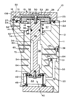
Reference is now made, more particularly, to Figures 1-5
of the drawings. Illustrated therein is a preferred embodiment
of a valve system, generally designated 10, for the emergency
or service release of air pressure from a brakepipe of a train.
This valve system 10 is used in a railway vehicle which is
remotely located from the lead locomotive. For example, such
valve system 10 could be disposed in an end-of train unit, or
in a slave locomotive.
Figures 1 and 2 are cross-sectional schematic views which
illustrate the major features of the invention. The
valve system 10 has a pressure containment structure 12 having
a cylindrical outer bore 14 formed therein. In the preferred
embodiment, pressure containment structure 12 has a housing 11
and a cover 18. A piston 16 is mounted for axial movement
within such cylindrical outer bore 14. There is a first valve
chamber 53 disposed on a first side of piston 16 and a second
valve chamber 57 disposed on a second side of such piston 16.
A diaphragm 20 provides a seal between the piston 16 and
the cylindrical outer bore 14. The diaphragm 20 includes an
annular fold 22 for permitting relative axial movement of the
piston 16 within the cylindrical outer bore 14. The annular
7
CA 02246835 1998-09-08
fold 22 is directed away from the first valve chamber 53 and
toward the second valve chamber 57.
A first brakepipe pressure passageway, generally
designated 50, is provided to convey brakepipe air to the first
valve chamber 53. In the preferred embodiment shown, first
brakekpipe pressure passageway 50 includes a passageway 108 in
the cover 18, a housing brakepipe pressure passageway 54,
a filter plug 89 and a portion of outer brakepipe passageway
55. Such portion of the outer brakepipe passageway 55
terminates in a brakepipe pressure port 51. Srakepipe pressure
port 51 is for connection to the brakepipe (not shown).
A presently preferred embodiment of the cover 18 is
illustrated in Figures 3 and 4. As can be readily seen
therein, the cover 18 includes a plurality of holes 106 that
enable such cover 18 secured to the housing 11 by bolts or
screws (not shown). A fluid communication passageway 108 is
formed in the cover 18 which, after machining, may be closed at
its outermost end by a plug 111. Passageway 108 connects to a
port 104 which mates with the brakepipe pressure passage 54
formed in the housing 11.
A control pressure connection 75 is provided for conveying
air from a control chamber 102 to the second valve chamber 57.
In the presently preferred embodiment illustrated in the
drawing Figures, the control pressure connection 75 includes a
control pressure passageway 70, a control pressure choke 72 and
a choked control pressure passageway 74.
8
CA 02246835 1998-09-08
There is a biasing means 52 provided for urging the piston
16 to move toward the first valve chamber 53. In the presently
preferred embodiment of the invention, such biasing means 52 is
a spring mounted in compression in the second valve chamber 57.
A stem 26 is connected to the piston 16 and a brakepipe
exhaust valve, generally designated 40, having a moveable
sealing portion 42 is connected to the stem 26. The moveable
sealing portion 42 seats against a valve seat 41. The
brakepipe exhaust valve 40 is closed when the piston 16 is
moved toward the first valve chamber 53 and is opened when the
piston 16 is moved toward the second valve chamber 57.
An exhaust chamber 38, connected to atmosphere, is
disposed on a first side of the brakepipe exhaust valve 40.
Preferably, this connection to atmosphere is through a
passageway 84 to a flapper valve 39.
There is also a brakepipe pressure chamber 44 located on
a second side of the brakepipe exhaust valve 40. The brakepipe
pressure chamber 44 is connected by second brakepipe pressure
passageway 120 to the brakepipe pressure connection so that
when the brakepipe exhaust valve 40 is opened, the brakepipe
(not shown) is vented to the exhaust chamber 38. In the
presently preferred embodiment, second brakepipe pressure
passageway 120 includes a filter 46, an outer brakepipe
pressure chamber 48, and outer brakepipe passageway 55.
Brakepipe pressure port 51 is for connection to the brakepipe.
9
CA 02246835 1998-09-08
When the control chamber 102 is supplied with air, at
brakepipe pressure, the brakepipe exhaust valve 40 is closed
and when a control pressure in the control chamber 102 is
reduced by venting to atmosphere the brakepipe exhaust valve 40
is opened and brakepipe air is exhausted to atmosphere through
the second brakepipe pressure passageway 120.
An annular sleeve 25 is attached to the pressure
containment structure 12. The annular sleeve 25 protrudes into
the fold 22 of the diaphragm 20 to prevent the diaphragm 20
from inverting if the pressure in the brakepipe drops below the
pressure in the control chamber 102, at a time when the piston
16 is positioned toward the first valve chamber 53. The
situation in which the brakepipe pressure drops below the
pressure in the control chamber 102 may occur if the brakepipe
of the train fails, so that its pressure drops, and no signal
is received by the remote unit or end of train unit to reduce
the pressure in the control chamber 102. The purpose of the
present invention is to prevent damage to the diaphragm 20 in
that case. Preferably, the annular sleeve 25 is a portion of
the cover 18.
It should be noted that in each of the schematic drawing
Figures 1 and 2, passageways which are aligned on opposite
sides of exhaust chamber 38 are connected to each other.
Control pressure connection 75, preferably, is formed in
the housing 11. It, preferably, consists of the control
CA 02246835 1998-09-08
pressure passageway 70, choke 72 and choked control pressure
passageway 74.
It is presently preferred that the diaphragm 20 have a
circumferential ridge 24 for fitting within a circular groove
27 which may be formed either in the cover 18 or, preferably,
in the housing 11.
It is preferred that such diaphragm 20 be clamped between
the cover 18 and the housing 11 to form a seal between such
cover 18 and housing 11.
As illustrated in Figure 5, the cylindrical outer bore 14,
preferably, has a rounded circumferential outside corner 110 to
guide the diaphragm 20 into annular fold 22. Likewise, the
annular sleeve 25, preferably, includes a rounded
circumferential inside corner 112 to guide such diaphragm 20
into annular fold 22.
Reference to Figure 1 shows that the stem 26 is disposed
within cylindrical bore 34 in housing 11 and is, preferably,
sealed by an O-ring sealing member 36.
A diaphragm retainer plate 28 is provided to hold
diaphragm 20 against the piston 16. Such piston 16,
preferably, has a rounded circumferential outside corner 114 to
guide the diaphragm 20 into annular fold 22. Likewise, the
diaphragm retainer plate 28, preferably, has a curved rim
portion 31 to guide such diaphragm 20 into annular fold 22.
Diaphragm retainer plate 28 is, preferably, attached to the
piston 16 by a threaded fastener 30. An O-ring sealing member
11
CA 02246835 1998-09-08
32 is provided to prevent lose of air around such threaded
fastener 30.
As illustrated in Figure 2, the valve system 10,
preferably, includes an emergency solenoid valve 82 that is
connected by a passageway 56 to the second valve chamber 57.
Emergency solenoid valve 82 is also connected by a passageway
80 to the exhaust chamber 38. In this manner, the second valve
chamber 57 can be vented through such emergency solenoid valve
82 to the exhaust chamber 38 so that the valve 40 can be opened
for an emergency release of brakepipe air. Emergency solenoid
valve 82 includes an electrical connection 120 to a control
system 100 to be controlled thereby.
Also, as shown in Figure 2, the valve system 10,
preferably, includes a pressure transducer 90 having electrical
connection 122 to a control system 100. The pressure
transducer 90 measures the air pressure present in housing
brakepipe pressure passageway 54.
Valve system 10, preferably, also includes a release
solenoid valve 85 having an electrical connection 124 to
control system 100. The release solenoid valve 85 is attached
to passageway 88 which, in turn, is connected to passageway 56
which, in turn, is connected to the second valve chamber 57.
Such release solenoid valve 85 is also connected to passageway
86 which is connected to passageway 54 and hence to the first
valve chamber 53. When the release solenoid valve 85 is
opened, the first valve chamber 53 has fluid connection to the
12
CA 02246835 1998-09-08
second valve chamber 57 to equalize pressures in the first
valve chamber 53 and the second valve chamber 57, so that
spring 52 pushes piston 16 toward the first valve chamber 53
and exhaust valve 40 is closed. This feature is employed at
the end of a service brake application.
Additionally, the valve system 10, preferably, includes a
service supply solenoid valve 63 that is electrically connected
by the electrical connection 126 to the control system 100.
When it is energized, service supply solenoid valve 63 receives
brakepipe air through passageway 64 from the filter plug 89
and supplies it through passageway 62 and a service supply
choke 66 to control pressure passageway 70 and thence to
control volume 102.
Valve system 10 also preferably includes a service exhaust
solenoid valve 59 having an electrical connection 128 to the
control system 100. When it is opened, it receives air through
passageway 58 from control pressure passageway 70 and hence
from control volume 102. It admits the air from passageway 58
to passageway 60 which is connected to flapper valve 39 through
exhaust choke 65.
Housing 11 is a flowblock in which ports 94 and 92 are,
preferably, included as test ports where pressure can be
measured during maintenance.
While a presently preferred and various additional
alternative embodiments of the instant invention have been
described in detail above, in accordance the patent statutes,
13
CA 02246835 1998-09-08
it should be recognized that various other modifications and
adaptations of the invention may be made by those persons who
are skilled in the relevant art without departing from either
the spirit of the invention or the scope of the appended
claims.
14