Note: Descriptions are shown in the official language in which they were submitted.
CA 02247033 2000-10-25
16975
-1-
LIQUID CONTAINMENT AND DISPENSING DEVICE
WITH IMPROVED POSITION INDICATING INDICIA
Cross-Reference
This application is directed to improvements in the invention of U.S. patent
No. 5,784,087 of July 21, 1998.
Field of the Invention
This invention relates to a liquid containment device with a self contained
pump for dispensing liquid in small doses of a predetermined volume. More
particularly, this invention relates to a replaceable containment device of
the
foregoing character which is useful in an ink jet printer for containing a
supply of
printing ink and for dispensing the printing ink to a printing head upon the
actuation
of the self contained pump.
Background and Brief Descri,~tion of the Invention
U.S. patent No. 5,784,087 filed by Bruce Cowger and Norman Pawlowski,
Jr., for an invention entitled "Ink Supply For An Ink-Jet Printer," describes
an ink
supply for an ink jet printer that is separate from the printer ink pen, and
can be
replaced upon the emptying of the ink supply without the need to replace the
printer
ink pen. The ink supply of the aforesaid U.S. patent incorporates a self
contained
pumping device for dispensing ink from a pumping chamber, and describes, as an
embodiment of such a pumping device, a bellows pump. However, a bellows pump
requires a relatively large extended surface of a semi-rigid material, such as
a
polymetric material, and is subject to a relatively high rate of oxygen and
moisture
transfer through the material of the bellows. This oxygen and/or moisture
transfer
can result in the degradation of the ink within the ink supply, especially in
a printer
that is used only infrequently. Further, the bellows is subject to
CA 02247033 2000-10-25
16975
-2-
leakage at the location of its attachment to another portion of the ink
supply.
According to the aforesaid U.S. patent No. 5,784,087 these and other problems
associated with the use of a bellows can be avoided by the use of a pumping
device
having a rigid perimetrical wall, preferably formed integrally with the
associated
chassis structure of the ink supply, with a linearly acting pumping member
that is
moveable within a pumping chamber defined by the rigid wall to pressurize ink
within the pumping chamber, and a flexible moisture and oxygen barner film
heat
sealed to an edge of the perimetrical wall in a continuous pattern and
overlying the
pumping member.
An ink supply according to the aforesaid U.S. patent No. 5,784,087 must be
properly oriented before it can be inserted in a docking bay of an ink jet
printer in
which it is to be used. This is especially important for a replaceable ink
supply
because replacement ink supply units are likely to be installed by a user
personnel,
who may not be as properly trained in replacement techniques as ink supply
manufacturer service personnel. It has now been found that the protective
shell and
cap of an ink supply can be manufactured with external characteristics that
make it
easier for the user personnel to properly orient a replacement ink supply unit
before
inserting it in a docking bay of a printer.
Accordingly, it is an object of the present invention to provide an improved
liquid containing and dispensing device, and is corollary an object of the
present
invention to provide an improved device of the foregoing character that is
useful in
containing and dispensing ink in an ink jet printer.
More particularly, it is an object of the present invention to provide a
liquid
containment and dispensing device with an improved indicia for indicating the
correct position of the device during the step of inserting the device in an
assembly
in which it is to be used and it is a corollary object of the present
invention to
provide a device of the foregoing character that is useful in containing and
dispensing ink in an ink jet printer.
CA 02247033 1998-11-30
16975 - 3 -
For a further understanding of the present invention and the objects thereof,
attention is directed to the drawing and the following brief description
thereof, to the
detailed description of the preferred embodiment of the invention, and to the
appended claims.
Brief Description of the Drawing
Fig. 1 is a side view of a liquid containment and dispensing device according
to an embodiment of the present invention;
Fig. 2 is a an exploded view of the device of Fig. l;
Fig. 3 is a plan view of the device of Figs. 1 and 2 taken on line 3-3 of Fig.
l;
Fig. 4 is a plan view of a component of the device of Figs. 1-3 taken on line
4-
4 of Fig. 5;
Fig. 5 is a side view of the component of Fig. 4;
Fig. 6 is a plan view of the component of Figs. 4 and 5 taken on line 6-6 of
Fig. 5;
Fig. 7 is a fragmentary sectional view taken on line 7-7 of Fig. 3 and at an
enlarged scale;
Fig. 8 is a fragmentary exploded view of a portion of the device of Figs. 1-7;
Fig. 9 is a fragmentary view similar to Fig. 8 showing the elements of Fig. 8
in
assembled relationship to one another;
Figs. 10 and 11 are perspective views showing alternative embodiments of a
liquid containment and dispensing device according to the present invention;
and
Figs. 12 and 13 are fragmentary perspective views showing further alternative
embodiments of a liquid containment and dispensing device according to the
present
invention.
Detailed Description of the Preferred Embodiment
CA 02247033 2000-10-25
16975
-4-
an ink containment and dispensing device in accordance with an embodiment
of the invention described in the aforesaid U.S. patent No. 5,784,087 is
identified in
Fig. 1 by reference numeral 10. The device 10 has a hard protective shell 12
which
contains a flexible pouch 14 for containing ink. The shell 12 is attached to a
chassis
16, which houses a pump 18 and a fluid outlet 20. A protective cap 22 is
attached to
the chassis 16 and a label 24 is glued to the outside of the shell 12 and cap
22
elements of the device 10 to secure the shell 12, chassis 16, and cap 22
firmly
together. The cap 22 is provided with apertures which allow access to the pump
and
the fluid outlet.
The device is adapted to be removably inserted into a docking bay (not
shown) within an ink jet printer. When the device 10 is inserted into the
printer, a
fluid inlet in the docking bay is adapted to engage the fluid outlet 20 to
allow ink
flow from the device 10 to the printer. An actuator (not shown) in the docking
bay
is adapted to engage the pump 18. Operation of the actuator causes the pump 18
to
provide ink in a series of small doses of a predetermined volume from the
flexible
pouch 14, through the fluid outlet 20, to the fluid inlet of the docking bay
and then
to the printer.
The chassis 16 is provided with a fill port 32 at one end and an exhaust port
34 at the other end. Ink can be added to the ink supply through the fill port
32 while
air displaced by the added ink is exhausted through the exhaust port 34. After
the
ink supply is filled, the fill port 32 is sealed with a ball 35 press fit into
the fill port
32.
A pumping chamber 36 having an open bottom is formed on the bottom of
the chassis 16 within a rigid perimetrical wall 37, which is preferably formed
integrally with chassis 16. As described in more detail below, the chamber 36
can
be pressured to supply ink to the printer without pressurizing the interior of
the
pouch 14. The top of the chamber 36 is provided with an inlet port 38 through
which ink may enter the chamber 36 from the pouch 14 by gravity and/or by a
negative pressure within chamber 36. An outlet port 40 through which ink may
be
expelled from the chamber 36 is also provided.
CA 02247033 1998-11-30
16975 - 5 -
A one-way flapper valve 42 located at the bottom of the inlet port 38 serves
to
limit the return of ink from the chamber 36 to the pouch 14. The flapper valve
42 is a
rectangular piece of flexible material. In the illustrated embodiment the
valve 42 is
positioned over the bottom of the inlet port 38 and is heat staked to the
chassis 16 at
the midpoints of its short sides. When the pressure within the chamber 36
drops
below that in the pouch 14, the unstaked sides of the valve 42 each flex to
allow the
flow of ink through the inlet port 38 and into the chamber 36. By heat staking
the
valve 42 to the chassis 16 along an opposed pair of sides, less flexing of the
valve 42
is required or permitted than would be the case if the valve 42 were staked
only along
a single side, thereby ensuring that it closes more securely, and this effect
is enhanced
by doing the heat staking at the midpoints of the shorter sides, as opposed to
the
longer sides.
In the illustrated embodiment the flapper valve 42 is made of a two ply
material. The outer ply is a layer of low density polyethylene 0.0015 inches
thick.
The inner ply is a layer of polyethylene terephthalate (PET) 0.0005 inches
thick. The
illustrated flapper valve 42 is approximately 5.5 millimeters wide and 8.7
millimeters
long. Such a material is impervious to the flow of ink therethrough when the
valve 42
is in its closed position.
The bottom of the chamber 36 is covered with a flexible diaphragm 44. The
diaphragm 44 is slightly larger than the opening at the bottom of the chamber
and is
sealed around the free edge of the perimetrical wall 37 that defines the
chamber 36.
The excess material in the oversized diaphragm 44 allows the diaphragm to flex
up
and down to vary the volume of the chamber 36. In the illustrated device, the
displacement of the diaphragm 44 allows the volume of the chamber 36 to be
varied
by about 0.7 cubic centimeters. The fully expanded volume of the illustrated
chamber
36 is between about 2.2 and 2.5 cubic centimeters.
In the illustrated embodiment, the diaphragm 44 is made of a multi-ply
material having a layer of low density polyethylene 0.0005 inches thick, a
layer of
adhesive, a layer of metallized polyethylene terephthalate (PET) 0.00048
inches thick,
CA 02247033 1998-11-30
16975 - 6 -
a layer of adhesive, and a layer of low density polyethylene 0.0005 inches
thick. Of
course, other suitable materials may also be used to form the diaphragm 44.
The
diaphragm 44 in the illustrated embodiment is heat staked, using conventional
methods, to the free edge of the wall 37 of the chamber 36. During the heat
staking
process, the low density polyethylene in the diaphragm will seal any folds or
wrinkles
in the diaphragm 44. The diaphragm 44, thus, is impervious to the transmission
of
oxygen and moisture therethrough, thereby safeguarding the ink in the chamber
36
from degradation by exposure to any such substance.
Within the chamber 36 a pressure plate 46 is positioned adjacent the
diaphragm 44, the pressure plate 46 serving as a piston with respect to the
chamber 36. A pump spring 48, made of stainless steel in the illustrated
embodiment,
biases the pressure plate 46 against the diaphragm 44 to urge the diaphragm
outward
so as to expand the size of the chamber 36. One end of the pump spring 48 is
received
on a spike 50 formed on the top of the chamber 36 and the other end of the
pump
spring 48 is received on a spike 52 formed on the pressure plate 46 in order
to retain
the pump spring 48 in position. The pressure plate 46 in the illustrated
embodiment is
molded of high density polyethylene.
A hollow cylindrical boss 54 extends downward from the chassis 16 to form
the housing of the fluid outlet 20, the boss 54 being formed integrally with
the chassis
16. A bore 56 of the hollow boss 54 has a narrow throat 54a at its lower end.
A
sealing ball 58, made of stainless steel in the illustrated embodiment, is
positioned
within the bore 56. 'The sealing ball 58 is sized such that it can move freely
within the
bore 56, but cannot pass through the narrow throat portion 54a thereof. A
sealing
spring 60 is positioned within the bore 56 to urge the sealing ball 58 against
the
narrow throat 54a to form a seal and prevent the flow of ink through the fluid
outlet.
A retaining ball 62, made of stainless steel in the illustrated embodiment, is
press fit
into the top of the bore to retain the sealing spring 60 in place. The bore 56
is
configured to allow the free flow of ink past the retaining ball 62 and into
the bore 56.
CA 02247033 1998-11-30
16975 - 7 -
A raised manifold 64 is formed on the top of the chassis 16. The manifold 64
forms a cylindrical boss around the top of the fill port 32 and a similar boss
around the
top of the inlet port 38 so that each of these ports is isolated. The manifold
64 extends
around the base of the fluid outlet 20 and the outlet port 40 to form an open-
topped
conduit 66 joining the two outlets.
The flexible ink pouch 14 is attached to the top of the manifold 64 so as to
form a top cover for the conduit 66. In the illustrated embodiment, this is
accomplished by heat staking a rectangular plastic sheet 68 to the top surface
of the
manifold 64 to enclose the conduit 66. In the illustrated embodiment, the
chassis 16
molded of high density polyethylene and the plastic sheet is low density
polyethylene
that is 0.002 inches thick. These two materials can be easily heat staked to
one
another using conventional methods and are also readily recyclable.
After the plastic sheet 68 is attached to the chassis 16, the sheet is folded
and
sealed around its two sides and top to form the flexible ink pouch 14. Again;
in the
illustrated embodiment, heat staking can be used to seal the perimeter of the
flexible
pouch 14. The plastic sheet over the fill port 32 and over the inlet port 38
can be
punctured, pierced, or otherwise removed so as not to block the flow of ink
through
these ports.
Although the flexible pouch 14 provides an ideal way to contain ink, it may be
easily punctured or ruptured and allows a relatively high amount of water loss
from
the ink. Accordingly, to protect the pouch 14 and to limit water loss, the
pouch 14 is
enclosed within the protective shell 12. In the illustrated embodiment, the
shell 12 is
made of clarified polypropylene, which is sufficiently translucent to permit
inspection
of the ink within the pouch 14 to determine that an adequate volume of ink
remains
for proper operation of the printer. A thickness of about one millimeter has
been
found to provide robust protection and to prevent unacceptable water loss from
the
ink. However, the material and thickness of the shell may vary in other
embodiments.
The top of the shell 12 has a number of raised ribs 70 to facilitate gripping
of
the shell 12 as it is inserted in or withdrawn from the docking bay. A
vertical rib 72
CA 02247033 1998-11-30
16975 - 8 -
projects laterally from each side of the shell 12. The vertical rib 72 can be
received
within a slot (not shown) in the docking bay to provide lateral support and
stability to
the ink supply when it is positioned within the printer. The bottom of the
shell 12 is
provided with two circumferential grooves or recesses 76 which engage two
circumferential ribs or beads 78 formed on a depending perimetrical wall 79 of
the
chassis 16 to attach the shell 12 to the chassis 16 in a snap fit.
The attachment between the shell 12 and the chassis 16 should, preferably, be
snug enough to prevent accidental separation of the chassis from the shell and
to resist
the flow of ink from the shell should the flexible reservoir develop a leak.
However,
it is also desirable that the attachment not form a hermetic seal to allow the
slow
ingress of air into the shell as ink is depleted from the reservoir 14 to
maintain the
pressure inside the shell generally the same as the ambient pressure.
Otherwise, a
negative pressure may develop inside the shell and inhibit the flow of ink
from the
reservoir. The ingress of air should be limited, however, in order to maintain
a high
humidity within the shell and minimize water loss from the ink.
In the illustrated embodiment, the shell 12 and the flexible pouch 14 which it
contains have the capacity to hold approximately thirty cubic centimeters of
ink. The
shell is approximately 67 millimeters wide, 15 millimeters thick, and 60
millimeters
high. The flexible pouch 14 is sized so as to fill the shell without undue
excess
material. Of course, other dimensions and shapes can also be used depending on
the
particular needs of a given printer.
To fill the device 10, ink can be injected through the fill port 32. As it is
filled, the flexible pouch 14 expands so as to substantially fill the shell
12. As ink is
being introduced into the pouch, the sealing ball 58 can be depressed to open
the fluid
outlet and a partial vacuum can be applied to the fluid outlet 20. The partial
vacuum
at the fluid outlet causes ink from the pouch 14 to fill the chamber 36, the
conduit 66,
and the bore of the cylindrical boss 54 such that little, if any, air remains
in contact
with the ink. The partial vacuum applied to the fluid outlet also speeds the
filling
process. To further facilitate the rapid filling of the pouch, an exhaust port
34 is
CA 02247033 1998-11-30
16975 - 9 -
provided to allow the escape of air from the shell as the reservoir expands.
Once the
ink supply is filled, a ball 35 is press fit into the fill port 32 to prevent
the escape of
ink or the entry of air.
Of course, there are a variety of other ways which can also be used to fill
the
present ink containment and dispensing device. In some instances, it may be
desirable
to flush the entire device with carbon dioxide prior to filling it with ink.
In this way,
any gas trapped within the device during the filling process will be carbon
dioxide,
not air. This may be preferable because carbon dioxide may dissolve in some
inks
while air may not. In general, it is preferable to remove as much gas from the
device
as possible so that bubbles and the like do not enter the print head or the
trailing tube.
The protective cap 22 is placed on the device 10 after the reservoir is
filled.
The protective cap is provided with a groove 80 which receives a rib 82 on the
chassis
to attach the cap to the chassis. The cap 22 carnes a plug 84 which plugs the
exhaust
port 34 to limit the flow of air into the chassis and reduce water loss from
the ink. A
stud 86 extends from each end of the chassis 16 and is received within an
aperture in
the cap 22 to aid in aligning the cap and to strengthen the union between the
cap and
the chassis. The free ends of the studs 86, which extend beyond the apertures
of the
cap 22, are preferably deformed after the cap 22 is in place, for example, by
contacting them with a heated tool, to provide a tamper resistant attachment
of the
cap 22 to the chassis 16. Further, the label 24 is glued to the sides of the
device 10 to
hold the shell 12, chassis 16, and cap 22 firmly together. In the illustrated
embodiment, a hot-melt pressure sensitive or other adhesive is used to adhere
the label
in a manner that prevents the label from being peeled off and inhibits
tampering with
the ink supply.
The cap 22 in the illustrated embodiment is provided with a vertical rib 90
protruding from each side. The rib 90 is an extension of the vertical rib 72
on the
shell and is received within the slot provided in the docking bay in a manner
similar to
the vertical rib 72. In addition to the rib 90, the cap 22 has protruding keys
92 located
on each side of the rib 90. One or more of the keys 92 can be optionally
deleted or
CA 02247033 1998-11-30
16975 - 10 -
altered so as to provide a unique identification of the particular ink supply
by color or
type. Mating keys (not shown), identifying a particular type or color of ink
supply
can be formed in the docking bay. In this manner, a user cannot inadvertently
insert
an ink supply of the wrong type or color into a docking bay. This arrangement
is
particularly advantageous for a multi-color printer where there are adjacent
docking
bays for ink supplies of various colors.
In the embodiment of Fig. 10, elements that correspond to the elements of the
embodiment of Figs. 1-9 are identified by a 100 series numeral, the last two
digits of
which correspond to the two digits of the corresponding element of the
embodiment
of Figs. 1-9.
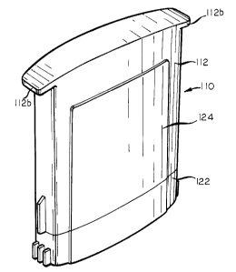
The ink containment and dispensing device of Fig. 10 is generally identified
by the reference numeral 110 and, except as hereinafter described, corresponds
to the
device 10 of Figs 1-9. The device 110 has a hard protective shell 112 that is
open at
one end, and the open end 112 is normally closed by a protective cap 122. A
label
124 is glued to the sides of the device 110 to hold the shell 112 and the cap
122 firmly
together. Preferably, a hot-melt pressure sensitive or other adhesive is used
to adhere
the label 124 to the shell 112 and the cap 122 in a manner that prevents the
label 124
from being peeled off and inhibits tampering with the ink supply within the
device 110.
The end of the shell 112 that is away from the end that is closed by the cap
122
is the end that is at the top of the device 110 when the device 110 is
properly oriented
to be inserted in a docking bay of an associated ink jet printer (not shown).
To make
the proper orientation of the device 110 abundantly clear to a person
installing a
device 110 in a printer, the shell is provided with an opposed pair of
outwardly
projecting tabs 112a, 112b along the shorter pair of its sides. The tabs 112a,
112b
serve to assist such a person in grasping a device 110 for insertion of a
device I 10 in a
printer or for the removal of an empty device 110 from the printer, and
naturally
indicate the proper orientation of the device 110 at the time of its insertion
into the
printer. The shell 112 of the device 110 may be relatively inexpensively
molded from
CA 02247033 1998-11-30
16975 - 11 -
a suitable thermoplastic material in a mold of simple design.
In the embodiment of the invention illustrated in Fig. 11, elements
corresponding to the elements of the embodiment of Figs. 1-9 are identified by
a 200
series numeral, the last two digits which are the digits of the corresponding
element of
the invention of Figs. 1-9.
The ink containment and dispensing device of Fig. 11 is generally identified
by reference numeral 210, and except as hereinafter described, corresponds to
the
device 10 of Figs. 1-9. The device 210 has a hard protective shell 212 that is
open at
one end and the open end of the shell 212 is closed by a protective cap 222.
The end of the shell 212 that is away from the end that is closed by the cap
222
is the end that is at the top of the device 210 when the device 210 is ready
for
insertion in a docking bay of an associated ink jet printer (not shown). To
make the
proper orientation of the device 210 abundantly clear to a person installing
the device
210 in a printer, the shell 212 is provided with an opposed pair of
longitudinally
extending, outwardly projecting ribs 212a, 212b along the shorter pair of its
sides.
The shell 212 is also provided with a spaced apart plurality of transversely
extending
ribs 212c, 212d, 212e, 212f that intersect the longitudinally extending rib
212a;
likewise the shell 212 is provided with a spaced apart plurality of
transversely
extending ribs 212g, 212h, 212i, 212j that intersect the longitudinally
extending rib
212b.
The ribs 212a, 212b, with their associated transversely extending ribs 212c,
212d, 212e, 212f, 212g, 212h, 212i, 212j, serve to very positively assist a
person
grasping a device 210 for insertion of the device 210 into a printer, or for
removal of
an empty device 210 from the printer, and naturally indicate the proper
orientation of
the device 210 at the time of its insertion into the printer. The shell 212 of
the
device 210 may be manufactured in its illustrated complex configuration from a
suitable thermoplastic material by molding.
In the embodiment of the invention illustrated in Fig. 12, elements
corresponding to the elements of Figs. 1-9 are identified by a 300 series
numeral, the
CA 02247033 1998-11-30
16975 - 12 -
last two digits of which are the two digits of the corresponding element of
the
invention of Figs. 1-9.
The ink containment and dispensing device of Fig. 12 is generally identified
by reference numeral 310 and, except as hereinafter described, corresponds to
the
device 10 of Figs. 1-9. The device 310 has a hard protective shell 312 that is
open at
one end, and the open end of the shell 312 is closed by a protective cap 322.
A label
324 is glued to the sides of the device 310 to hold the shell 312 and cap 322
firmly
together. In the illustrated embodiment, a hot-melt pressure sensitive or
other
adhesive is used to adhere the label 324 to the shell 312 and the cap 322 in a
manner
that prevents the label from being peeled off and inhibits tampering with the
ink
supply.
The shell 312 has an opposed pair of shorter sides interspersed with an
opposed pair of longer sides and each of its shorter sides tapers inwardly
near the
closed end of the shell 312, as is illustrated at 312a, to provide a gripping
surface for
the fingers of a user involved in installing the device 310 in a printer.
Further, the
shell 312 is provided with a radially outwardly projecting flange 312b above
the level
of the tapered portion 312a to further assist a user in grasping the device
310 at the
tapered portion 312a and an opposed tapered portion, not shown.
Each of the opposed shorter sides of the shell 312 is also provided with an
outwardly projecting flange, for example the flange 312c, below the level of
the
tapered portion 312a. The purpose of the flange 312c is to inhibit insertion
of the
device 310 into the docking bay of a printer in an inverted orientation of the
device 310.
Each of the opposed shorter sides of the shell 312 is also provided with an
outwardly projecting and longitudinally extending rib 312d. The purpose of the
rib
312d is to assist in the insertion of the device 310 into the docking bay of a
printer,
and the rib 312d is provided with an eccentrically positioned notch 312e to
positively
lock the device 310 into the docking bay of the printer. The shell 312 may be
manufactured in its illustrated, complex configuration from a suitable
thermoplastic
CA 02247033 1998-11-30
16975 - 13 -
material by molding.
In the embodiment of the invention illustrated in Fig. 13, elements
corresponding to the elements of Figs. 1-9 are identified by a 400 series
numeral, the
last two digits of which are the two digits of the corresponding element of
the
invention of Figs. 1-9.
The ink containment and dispensing device of Fig. 13 is generally identified
by reference numeral 410 and, except as hereinafter described, corresponds to
the
device 10 of Figs. 1-9. The device 410 has a hard protective shell 412, which
is open
at one end, and the open end of the shell 412 is closed by a protective cap
422.
The shell 412 has an opposed pair of shorter sides interspersed with an
opposed pair of longer sides, and each of the shorter sides has an inwardly
tapered
finger gripping portion near the upper end thereof, in the illustrated
orientation of the
device 410, the inwardly tapered portion illustrated in Fig. 13 being
identified by
reference numeral 412a. The inwardly tapered portions of the shell 412,
including the
portion 412a, provide a location to be gripped by the fingers of the person
installing
the device 410 into, or removing the device 410 from, a docking bay of an ink
jet
printer.
Each of the opposed shorter sides of the shell 412 of the device 410 is
further
provided with an outwardly projecting tab above the level of the tapered
portion, such
as the tab 412b which is positioned above the tapered portion 412a of the
shell 412.
Each of the tabs, such as the tab 412b, is concave in an upwardly facing
direction and
serves to prevent the device 410 from being inserted into the docking bay of a
printer
in an inverted orientation.
The shell 412 of the device 410 may be manufactured in its illustrated
complex configuration from a suitable thermoplastic material by molding.
The liquid containment and dispensing device of the various embodiments of
the present invention has been specifically described as a device for
containing and
dispensing a supply of printing ink in an ink jet printer as the preferred
embodiment
of the invention. However, it is also contemplated that the present invention
can
CA 02247033 2000-10-25
1697 - 14 -
easily be adapted to the containment and dispensing of other Newtonian (low
viscosity) liquids.
Although the best mode contemplated by the inventor for carrying out the
present invention as of the filing date hereof has been shown and described
herein. it
will be apparent to those skilled in the art that suitable modifications,
variations and
equivalents may be made without departing from the scope of the invention,
such
scope being limited solely by the terms of the following claims and the legal
equivalents thereof.