Language selection

Search

Patent 2247218 Summary

Third-party information liability

Some of the information on this Web page has been provided by external sources. The Government of Canada is not responsible for the accuracy, reliability or currency of the information supplied by external sources. Users wishing to rely upon this information should consult directly with the source of the information. Content provided by external sources is not subject to official languages, privacy and accessibility requirements.

Claims and Abstract availability

Any discrepancies in the text and image of the Claims and Abstract are due to differing posting times. Text of the Claims and Abstract are posted:

  • At the time the application is open to public inspection;
  • At the time of issue of the patent (grant).
(12) Patent: (11) CA 2247218
(54) English Title: STIRRUP
(54) French Title: ETRIER
Status: Expired and beyond the Period of Reversal
Bibliographic Data
(51) International Patent Classification (IPC):
  • B68C 3/02 (2006.01)
(72) Inventors :
  • MARTIN, JACK L. (United States of America)
(73) Owners :
  • LIBERTYVILLE SADDLE SHOP, INC.
(71) Applicants :
  • LIBERTYVILLE SADDLE SHOP, INC. (United States of America)
(74) Agent: MACRAE & CO.
(74) Associate agent:
(45) Issued: 2006-12-19
(22) Filed Date: 1998-09-15
(41) Open to Public Inspection: 1999-08-11
Examination requested: 2003-06-09
Availability of licence: N/A
Dedicated to the Public: N/A
(25) Language of filing: English

Patent Cooperation Treaty (PCT): No

(30) Application Priority Data:
Application No. Country/Territory Date
022,098 (United States of America) 1998-02-11

Abstracts

English Abstract


A stainless steel stirrup with a rotatable foot plate
pivotally connected to the lower ends of the stirrup limbs and
including means for restricting the forward rotation of the
stirrup to a substantially horizontal position with respect to
the stirrup limbs but allowing the stirrup to rotate freely in a
backward direction through a range of approximately 90°.


Claims

Note: Claims are shown in the official language in which they were submitted.

CLAIMS
What is claimed is:
1. A stirrup comprising:
an inverted generally U-Shaped frame including two limbs
extending substantially the full arc of said stirrup, and an
attachment portion for a stirrup leather,
a foot plate pivotally mounted at the lower ends of said two
limbs,
pivot means pivotally interconnecting the lower ends of said
limbs and said foot plate,
coacting stop means formed on the lower ends of said limbs and
at the ends of said foot plate for limiting the forward
rotation of said foot plate with respect to said limbs, said
stop means being effective to restrict the forward rotation of
said foot plate to a position where it is substantially at
right angles with said limbs, said foot plate being freely
rotatable in a backward direction through a range of
approximately 90°.
10

2. The stirrup of claim 1 wherein
said coacting stop means comprise first shoulder means formed
on the lower ends of said limbs and second shoulder means
formed at each end of said foot plate.
3. The stirrup of claim 2 wherein
each end of said foot plate includes a protrusion integrally
formed therewith, said second shoulder means being formed on
the upper end of said protrusion.
4. The stirrup of claim 2 wherein
said first and second shoulder means lie in vertical plane
and are co-planar.
5. The stirrup of claim 1 wherein
said coacting stop means comprises first shoulder means formed
on the lower end of each of said limbs and second shoulder
means formed at each end of said foot plate, said first and
11

second shoulder means when in an abutting position being
effective to restrict further forward rotation of said foot
plate.
6. The stirrup of claim 1 wherein
said pivot means includes means defining transverse grooves
formed at each end of the foot plate, tongues formed on the
lower ends of said limbs and extending into said grooves and
pivot pins extending between said tongues and the walls
defining said transverse grooves.
7. The stirrup of claim 1 wherein
said foot plate is freely rotatable through a range of
approximately 90° with respect to said limbs from an extreme
forward position in which said foot plate is held in a
restricted position by said stop means at substantially right
angles with said limbs to an extreme backward position in
which said foot plate is substantially parallel to said limbs.
8. The stirrup of claim 1 wherein
12

said foot plate is constructed with an elongated aperture for
receiving therethrough a resilient foot pad.
13

Description

Note: Descriptions are shown in the official language in which they were submitted.


CA 02247218 1998-09-15
This invention relates to stirrups used in horse back
riding.
A principal object of the invention is to provide a
stirrup which will facilitate and promote the "heels down,
toes up" position of a rider's foot.
Another object is to provide a stirrup with a
feature which will minimize the undesirable forward tendency
or the "toes down" characteristic.
Another object is to provide a stirrup with a safety
feature wherein the forward rotation of the foot plate is
limited in order to minimize the possibility of a rider's foot

CA 02247218 1998-09-15
sliding through the stirrup and to provide a backward heels
down release in case of fall or accident.
A further object of the invention is to provide a
stirrup wherein the foot plate pivots or rotates backwards
with respect to the limbs in a range substantially between 0~
and 90~ to facilitate a "heels down, toes up" position for the
rider.
Another object of the invention is to provide
coacting stop means on the lower ends of the stirrup limbs and
at each end of the foot plate to limit the rotation of the
foot plate with respect to the limbs to Oo degrees in one
direction wherein the foot plate and the limbs are
substantially at right angles, to as much as 90 degrees in the
opposite direction.
Another object of the invention is to provide a
stirrup in which the foot plate is pivotable about the lower
ends of the stirrup limbs from a locked position in which the
foot plate is substantially perpendicular to the stirrup limbs
to a position wherein the foot plate is substantially parallel
2

CA 02247218 1998-09-15
to the stirrup limbs.
Another object is to provide a stirrup which takes
pressure off the ankle and calves of a rider and promotes a
stable and correct leg position.
Another object of the invention is to provide a
stirrup which facilitates mounting a horse by providing a
solid foot bed.
Additional objects and features of the invention
will become more apparent from the following description and
accompanying drawings.
Fig. 1 is a perspective view in elevation of the
stirrup embodying the invention herein;
Fig. 2 is an enlarged partial front view in
elevation of the right end of the stirrup of Fig. 1 showing
3

CA 02247218 1998-09-15
the pivotal connection between the lower end of the stirrup limb
and the end of the foot plate;
Fig. 3 is an enlarged partial right end view in
elevation of the pivotal connection between the lower end of the
stirrup limb and the end of the foot plate showing the coacting
stop means in abutting position and the stirrup limb and foot
plate in a locked position;
Fig. 4 is an enlarged partial end view in elevation of
the pivotal connection shown in Fig. 3 but with the foot plate
tilted backwards to permit a "heels down, toes up" position of a
rider's foot.
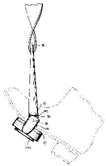
Fig. 5 is a right end view in elevation of the stirrup
of Fig. 1 showing the pivotal connection as seen in Fig. 4 and
showing in phantom a rider's boot tilting backwards in a "heels
down, toes up" position.
We refer now to the drawings wherein like reference
4

CA 02247218 1998-09-15
characters refer to like parts. Fig.l is a perspective view of a
stirrup 10 embodying the invention herein. The stirrup 10
comprises an inverted generally U-shaped frame 12 having Gwo
limbs 14 and 16 and an attachment portion 18 at the apex o~ the
frame. An aperture 20 in the attachment portion is provided to
accommodate a stirrup leather. The stirrup 10 also include~~a
foot plate 22 which is pivotally mounted at the lower ends of the
two limbs 14 and 16. The stirrup preferably is made of stainless
steel.
The foot plate 22 may be constructed with an elongated
aperture (not shown) to receive there through a foot pad 23
which, as is well known in the art, may be made of resilient
rubber-like material. The foot pad 23 usually is formed with an
enlarged bottom portion 23a which is designed to secure the foot
pad 23 in the aperture (not shown). The foot pad is easily
removable and interchangeable as wear may dictate.
Pivotal connections.formed at the ends of the foot
plate 22 permit the foot plate 22 to pivot about the lower ends
of the limbs 14 and 16. In the preferred embodiment the foot
plate 22 is formed with integral small protrusions 24 and 26 at

CA 02247218 1998-09-15
each end of the foot plate. These small protrusions 24 and 26
are designed to permit the construction of a pivotal connection
with the lower ends of the limbs 14 and 16 as close as possible
to the plane of the foot plate. Transverse grooves 28 and 30 are
formed in the protrusions 24 and 26 respectively to receive
tongues 32 and 34 integrally formed on the lower ends of the
limbs 14 and 16. Pivot pins 36 extending through the tongues 32,
34 and into protrusions 24 and 26 allow the foot plate 22 to
pivot about the lower ends of the limbs 14 and 16.
Stop means are provided on the stirrup limbs and foot
plate to define the limit of rotation of the foot plate with
respect to the stirrup limbs. These stop means include shoulders
38 formed at the ends of the foot plate on the upper ends of the
protrusions 24 and 26 and shoulders 40 formed on the lower ends
of each of the limbs 14 and 16 on each side of the tongues 32 and
34. When the foot plate is rotated forwardly so that the
shoulders 38 and 40 abut against each other as shown in Fig. 3
the foot plate 22 is in effect in a locked position, being
restricted from further forward rotation. In that position it is
at right angles with the limbs 14 and 16. The purpose of this
restriction is to prevent the undesirable forward tendency or
6

CA 02247218 1998-09-15
"toes down" characteristic. The foot plate is capable of
substantially 90o backward rotation relative to the limbs of the
stirrup but cannot rotate forwardly beyond the position where it
makes right angles with the stirrup limbs. This ability to freely
pivot 90~ in a backward direction assists the rider in
maintaining the "heels down, toes up" position in the stirrup.
Furthermore this capability of freely pivoting 90o makes it
possible for a rider to easily slip his foot out of the stirrup
in the event of a fall. When the foot plate 22 is in a locked
position horizontally as previously alluded to there is less
danger of the rider's foot slipping through the stirrup than with
a stirrup which allows the foot plate to pivot in both forward
and backward directions.
In certain riding activities a rider oftentimes stands
up in the stirrups. Even with the rider's full weight on the
stirrup the rider still should be able to keep heels down and
toes up. Some stirrups are constructed with a hinged connection
located substantially halfway between the apex of the stirrup and
the foot plate. Because of the location of that hinged
connection it is virtually impossible for a rider in a standing
position, for example, using such a stirrup, to pivot the foot
7

CA 02247218 1998-09-15
plate and maintain the appropriate "heels down" position because,
of the excessive leverage required. Amongst other disadvantages
this often results in a tremendous strain on the calves of the
rider's legs. A stirrup embodying the invention herein does not
present the aforementioned problem; quite to the contrary it
takes the pressure off the ankles and calves, keeps the heels
down and promotes a stable and correct leg position.
It will be apparent that I have advantageously provided
an improved stirrup in which the foot plate locks in a horizontal
position at right angles with the limbs resisting further forward
rotation. At the same time the foot plate pivots freely 900
in the backward direction only, to facilitate the correct "heels
down, toes up" position. This is unlike some other stirrups
which rotate or swing in both directions allowing the undesirable
forward tendency or "toes down" position of the foot. This
potentially allows a rider to put a foot all the way through the
stirrup and get it caught in the stirrup. The foot plate
pivoting freely 90o in the backward direction also permits the
foot to easily come free from the stirrup in the event of a fall.
The right angle locking feature can also assist in mounting. By
temporarily reversing the position of the stirrup the rider can
8

CA 02247218 1998-09-15
use the right angle locking feature to provide a sure footing.
Once mounted the stirrup can be reversed to its normal "heels
down" position.
While a preferred embodiment of the invention has been
disclosed, it will be appreciated that this is shown by way of
example only, and the invention is not to be limited thereto as
other variations will be apparent to those skilled in the art,
and the invention is to be given its fullest interpretation
within the terms of the following claims.
9

Representative Drawing
A single figure which represents the drawing illustrating the invention.
Administrative Status

2024-08-01:As part of the Next Generation Patents (NGP) transition, the Canadian Patents Database (CPD) now contains a more detailed Event History, which replicates the Event Log of our new back-office solution.

Please note that "Inactive:" events refers to events no longer in use in our new back-office solution.

For a clearer understanding of the status of the application/patent presented on this page, the site Disclaimer , as well as the definitions for Patent , Event History , Maintenance Fee  and Payment History  should be consulted.

Event History

Description Date
Time Limit for Reversal Expired 2010-09-15
Letter Sent 2009-09-15
Grant by Issuance 2006-12-19
Inactive: Cover page published 2006-12-18
Inactive: Final fee received 2006-10-10
Pre-grant 2006-10-10
Notice of Allowance is Issued 2006-08-30
Letter Sent 2006-08-30
Notice of Allowance is Issued 2006-08-30
Inactive: Approved for allowance (AFA) 2006-07-12
Inactive: Entity size changed 2003-09-10
Amendment Received - Voluntary Amendment 2003-08-29
Letter Sent 2003-07-09
Request for Examination Requirements Determined Compliant 2003-06-09
All Requirements for Examination Determined Compliant 2003-06-09
Request for Examination Received 2003-06-09
Inactive: Cover page published 1999-08-18
Application Published (Open to Public Inspection) 1999-08-11
Inactive: Single transfer 1999-03-11
Inactive: IPC assigned 1998-12-05
Classification Modified 1998-12-05
Inactive: First IPC assigned 1998-12-05
Inactive: Courtesy letter - Evidence 1998-11-03
Inactive: Filing certificate - No RFE (English) 1998-10-27
Filing Requirements Determined Compliant 1998-10-27
Application Received - Regular National 1998-10-23

Abandonment History

There is no abandonment history.

Maintenance Fee

The last payment was received on 2006-08-15

Note : If the full payment has not been received on or before the date indicated, a further fee may be required which may be one of the following

  • the reinstatement fee;
  • the late payment fee; or
  • additional fee to reverse deemed expiry.

Please refer to the CIPO Patent Fees web page to see all current fee amounts.

Fee History

Fee Type Anniversary Year Due Date Paid Date
Application fee - small 1998-09-15
Registration of a document 1999-03-11
MF (application, 2nd anniv.) - small 02 2000-09-15 2000-08-18
MF (application, 3rd anniv.) - small 03 2001-09-17 2001-08-24
MF (application, 4th anniv.) - small 04 2002-09-16 2002-08-19
Request for examination - small 2003-06-09
MF (application, 5th anniv.) - standard 05 2003-09-15 2003-08-25
MF (application, 6th anniv.) - standard 06 2004-09-15 2004-08-20
MF (application, 7th anniv.) - standard 07 2005-09-15 2005-09-12
MF (application, 8th anniv.) - standard 08 2006-09-15 2006-08-15
Final fee - standard 2006-10-10
MF (patent, 9th anniv.) - standard 2007-09-17 2007-08-08
MF (patent, 10th anniv.) - standard 2008-09-15 2008-08-11
Owners on Record

Note: Records showing the ownership history in alphabetical order.

Current Owners on Record
LIBERTYVILLE SADDLE SHOP, INC.
Past Owners on Record
JACK L. MARTIN
Past Owners that do not appear in the "Owners on Record" listing will appear in other documentation within the application.
Documents

To view selected files, please enter reCAPTCHA code :


To view images, click a link in the Document Description column. To download the documents, select one or more checkboxes in the first column and then click the "Download Selected in PDF format (Zip Archive)" or the "Download Selected as Single PDF" button.

List of published and non-published patent-specific documents on the CPD .

If you have any difficulty accessing content, you can call the Client Service Centre at 1-866-997-1936 or send them an e-mail at CIPO Client Service Centre.


Document
Description 
Date
(yyyy-mm-dd) 
Number of pages   Size of Image (KB) 
Representative drawing 1999-08-18 1 6
Abstract 1998-09-15 1 12
Description 1998-09-15 9 216
Claims 1998-09-15 4 69
Drawings 1998-09-15 3 66
Cover Page 1999-08-18 1 23
Representative drawing 2006-11-17 1 6
Cover Page 2006-11-17 1 28
Filing Certificate (English) 1998-10-27 1 163
Courtesy - Certificate of registration (related document(s)) 1999-04-14 1 117
Reminder of maintenance fee due 2000-05-16 1 111
Reminder - Request for Examination 2003-05-20 1 113
Acknowledgement of Request for Examination 2003-07-09 1 173
Commissioner's Notice - Application Found Allowable 2006-08-30 1 162
Maintenance Fee Notice 2009-10-27 1 169
Correspondence 1998-11-03 1 30
Correspondence 2006-10-10 1 31