Sélection de la langue

Search

Sommaire du brevet 2247218 

Énoncé de désistement de responsabilité concernant l'information provenant de tiers

Une partie des informations de ce site Web a été fournie par des sources externes. Le gouvernement du Canada n'assume aucune responsabilité concernant la précision, l'actualité ou la fiabilité des informations fournies par les sources externes. Les utilisateurs qui désirent employer cette information devraient consulter directement la source des informations. Le contenu fourni par les sources externes n'est pas assujetti aux exigences sur les langues officielles, la protection des renseignements personnels et l'accessibilité.

Disponibilité de l'Abrégé et des Revendications

L'apparition de différences dans le texte et l'image des Revendications et de l'Abrégé dépend du moment auquel le document est publié. Les textes des Revendications et de l'Abrégé sont affichés :

  • lorsque la demande peut être examinée par le public;
  • lorsque le brevet est émis (délivrance).
(12) Brevet: (11) CA 2247218
(54) Titre français: ETRIER
(54) Titre anglais: STIRRUP
Statut: Périmé et au-delà du délai pour l’annulation
Données bibliographiques
(51) Classification internationale des brevets (CIB):
  • B68C 3/02 (2006.01)
(72) Inventeurs :
  • MARTIN, JACK L. (Etats-Unis d'Amérique)
(73) Titulaires :
  • LIBERTYVILLE SADDLE SHOP, INC.
(71) Demandeurs :
  • LIBERTYVILLE SADDLE SHOP, INC. (Etats-Unis d'Amérique)
(74) Agent: MACRAE & CO.
(74) Co-agent:
(45) Délivré: 2006-12-19
(22) Date de dépôt: 1998-09-15
(41) Mise à la disponibilité du public: 1999-08-11
Requête d'examen: 2003-06-09
Licence disponible: S.O.
Cédé au domaine public: S.O.
(25) Langue des documents déposés: Anglais

Traité de coopération en matière de brevets (PCT): Non

(30) Données de priorité de la demande:
Numéro de la demande Pays / territoire Date
022,098 (Etats-Unis d'Amérique) 1998-02-11

Abrégés

Abrégé anglais


A stainless steel stirrup with a rotatable foot plate
pivotally connected to the lower ends of the stirrup limbs and
including means for restricting the forward rotation of the
stirrup to a substantially horizontal position with respect to
the stirrup limbs but allowing the stirrup to rotate freely in a
backward direction through a range of approximately 90°.

Revendications

Note : Les revendications sont présentées dans la langue officielle dans laquelle elles ont été soumises.


CLAIMS
What is claimed is:
1. A stirrup comprising:
an inverted generally U-Shaped frame including two limbs
extending substantially the full arc of said stirrup, and an
attachment portion for a stirrup leather,
a foot plate pivotally mounted at the lower ends of said two
limbs,
pivot means pivotally interconnecting the lower ends of said
limbs and said foot plate,
coacting stop means formed on the lower ends of said limbs and
at the ends of said foot plate for limiting the forward
rotation of said foot plate with respect to said limbs, said
stop means being effective to restrict the forward rotation of
said foot plate to a position where it is substantially at
right angles with said limbs, said foot plate being freely
rotatable in a backward direction through a range of
approximately 90°.
10

2. The stirrup of claim 1 wherein
said coacting stop means comprise first shoulder means formed
on the lower ends of said limbs and second shoulder means
formed at each end of said foot plate.
3. The stirrup of claim 2 wherein
each end of said foot plate includes a protrusion integrally
formed therewith, said second shoulder means being formed on
the upper end of said protrusion.
4. The stirrup of claim 2 wherein
said first and second shoulder means lie in vertical plane
and are co-planar.
5. The stirrup of claim 1 wherein
said coacting stop means comprises first shoulder means formed
on the lower end of each of said limbs and second shoulder
means formed at each end of said foot plate, said first and
11

second shoulder means when in an abutting position being
effective to restrict further forward rotation of said foot
plate.
6. The stirrup of claim 1 wherein
said pivot means includes means defining transverse grooves
formed at each end of the foot plate, tongues formed on the
lower ends of said limbs and extending into said grooves and
pivot pins extending between said tongues and the walls
defining said transverse grooves.
7. The stirrup of claim 1 wherein
said foot plate is freely rotatable through a range of
approximately 90° with respect to said limbs from an extreme
forward position in which said foot plate is held in a
restricted position by said stop means at substantially right
angles with said limbs to an extreme backward position in
which said foot plate is substantially parallel to said limbs.
8. The stirrup of claim 1 wherein
12

said foot plate is constructed with an elongated aperture for
receiving therethrough a resilient foot pad.
13

Description

Note : Les descriptions sont présentées dans la langue officielle dans laquelle elles ont été soumises.

CA 02247218 1998-09-15
This invention relates to stirrups used in horse back
riding.
A principal object of the invention is to provide a
stirrup which will facilitate and promote the "heels down,
toes up" position of a rider's foot.
Another object is to provide a stirrup with a
feature which will minimize the undesirable forward tendency
or the "toes down" characteristic.
Another object is to provide a stirrup with a safety
feature wherein the forward rotation of the foot plate is
limited in order to minimize the possibility of a rider's foot

CA 02247218 1998-09-15
sliding through the stirrup and to provide a backward heels
down release in case of fall or accident.
A further object of the invention is to provide a
stirrup wherein the foot plate pivots or rotates backwards
with respect to the limbs in a range substantially between 0~
and 90~ to facilitate a "heels down, toes up" position for the
rider.
Another object of the invention is to provide
coacting stop means on the lower ends of the stirrup limbs and
at each end of the foot plate to limit the rotation of the
foot plate with respect to the limbs to Oo degrees in one
direction wherein the foot plate and the limbs are
substantially at right angles, to as much as 90 degrees in the
opposite direction.
Another object of the invention is to provide a
stirrup in which the foot plate is pivotable about the lower
ends of the stirrup limbs from a locked position in which the
foot plate is substantially perpendicular to the stirrup limbs
to a position wherein the foot plate is substantially parallel
2

CA 02247218 1998-09-15
to the stirrup limbs.
Another object is to provide a stirrup which takes
pressure off the ankle and calves of a rider and promotes a
stable and correct leg position.
Another object of the invention is to provide a
stirrup which facilitates mounting a horse by providing a
solid foot bed.
Additional objects and features of the invention
will become more apparent from the following description and
accompanying drawings.
Fig. 1 is a perspective view in elevation of the
stirrup embodying the invention herein;
Fig. 2 is an enlarged partial front view in
elevation of the right end of the stirrup of Fig. 1 showing
3

CA 02247218 1998-09-15
the pivotal connection between the lower end of the stirrup limb
and the end of the foot plate;
Fig. 3 is an enlarged partial right end view in
elevation of the pivotal connection between the lower end of the
stirrup limb and the end of the foot plate showing the coacting
stop means in abutting position and the stirrup limb and foot
plate in a locked position;
Fig. 4 is an enlarged partial end view in elevation of
the pivotal connection shown in Fig. 3 but with the foot plate
tilted backwards to permit a "heels down, toes up" position of a
rider's foot.
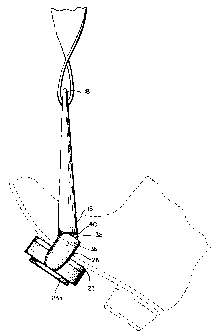
Fig. 5 is a right end view in elevation of the stirrup
of Fig. 1 showing the pivotal connection as seen in Fig. 4 and
showing in phantom a rider's boot tilting backwards in a "heels
down, toes up" position.
We refer now to the drawings wherein like reference
4

CA 02247218 1998-09-15
characters refer to like parts. Fig.l is a perspective view of a
stirrup 10 embodying the invention herein. The stirrup 10
comprises an inverted generally U-shaped frame 12 having Gwo
limbs 14 and 16 and an attachment portion 18 at the apex o~ the
frame. An aperture 20 in the attachment portion is provided to
accommodate a stirrup leather. The stirrup 10 also include~~a
foot plate 22 which is pivotally mounted at the lower ends of the
two limbs 14 and 16. The stirrup preferably is made of stainless
steel.
The foot plate 22 may be constructed with an elongated
aperture (not shown) to receive there through a foot pad 23
which, as is well known in the art, may be made of resilient
rubber-like material. The foot pad 23 usually is formed with an
enlarged bottom portion 23a which is designed to secure the foot
pad 23 in the aperture (not shown). The foot pad is easily
removable and interchangeable as wear may dictate.
Pivotal connections.formed at the ends of the foot
plate 22 permit the foot plate 22 to pivot about the lower ends
of the limbs 14 and 16. In the preferred embodiment the foot
plate 22 is formed with integral small protrusions 24 and 26 at

CA 02247218 1998-09-15
each end of the foot plate. These small protrusions 24 and 26
are designed to permit the construction of a pivotal connection
with the lower ends of the limbs 14 and 16 as close as possible
to the plane of the foot plate. Transverse grooves 28 and 30 are
formed in the protrusions 24 and 26 respectively to receive
tongues 32 and 34 integrally formed on the lower ends of the
limbs 14 and 16. Pivot pins 36 extending through the tongues 32,
34 and into protrusions 24 and 26 allow the foot plate 22 to
pivot about the lower ends of the limbs 14 and 16.
Stop means are provided on the stirrup limbs and foot
plate to define the limit of rotation of the foot plate with
respect to the stirrup limbs. These stop means include shoulders
38 formed at the ends of the foot plate on the upper ends of the
protrusions 24 and 26 and shoulders 40 formed on the lower ends
of each of the limbs 14 and 16 on each side of the tongues 32 and
34. When the foot plate is rotated forwardly so that the
shoulders 38 and 40 abut against each other as shown in Fig. 3
the foot plate 22 is in effect in a locked position, being
restricted from further forward rotation. In that position it is
at right angles with the limbs 14 and 16. The purpose of this
restriction is to prevent the undesirable forward tendency or
6

CA 02247218 1998-09-15
"toes down" characteristic. The foot plate is capable of
substantially 90o backward rotation relative to the limbs of the
stirrup but cannot rotate forwardly beyond the position where it
makes right angles with the stirrup limbs. This ability to freely
pivot 90~ in a backward direction assists the rider in
maintaining the "heels down, toes up" position in the stirrup.
Furthermore this capability of freely pivoting 90o makes it
possible for a rider to easily slip his foot out of the stirrup
in the event of a fall. When the foot plate 22 is in a locked
position horizontally as previously alluded to there is less
danger of the rider's foot slipping through the stirrup than with
a stirrup which allows the foot plate to pivot in both forward
and backward directions.
In certain riding activities a rider oftentimes stands
up in the stirrups. Even with the rider's full weight on the
stirrup the rider still should be able to keep heels down and
toes up. Some stirrups are constructed with a hinged connection
located substantially halfway between the apex of the stirrup and
the foot plate. Because of the location of that hinged
connection it is virtually impossible for a rider in a standing
position, for example, using such a stirrup, to pivot the foot
7

CA 02247218 1998-09-15
plate and maintain the appropriate "heels down" position because,
of the excessive leverage required. Amongst other disadvantages
this often results in a tremendous strain on the calves of the
rider's legs. A stirrup embodying the invention herein does not
present the aforementioned problem; quite to the contrary it
takes the pressure off the ankles and calves, keeps the heels
down and promotes a stable and correct leg position.
It will be apparent that I have advantageously provided
an improved stirrup in which the foot plate locks in a horizontal
position at right angles with the limbs resisting further forward
rotation. At the same time the foot plate pivots freely 900
in the backward direction only, to facilitate the correct "heels
down, toes up" position. This is unlike some other stirrups
which rotate or swing in both directions allowing the undesirable
forward tendency or "toes down" position of the foot. This
potentially allows a rider to put a foot all the way through the
stirrup and get it caught in the stirrup. The foot plate
pivoting freely 90o in the backward direction also permits the
foot to easily come free from the stirrup in the event of a fall.
The right angle locking feature can also assist in mounting. By
temporarily reversing the position of the stirrup the rider can
8

CA 02247218 1998-09-15
use the right angle locking feature to provide a sure footing.
Once mounted the stirrup can be reversed to its normal "heels
down" position.
While a preferred embodiment of the invention has been
disclosed, it will be appreciated that this is shown by way of
example only, and the invention is not to be limited thereto as
other variations will be apparent to those skilled in the art,
and the invention is to be given its fullest interpretation
within the terms of the following claims.
9

Dessin représentatif
Une figure unique qui représente un dessin illustrant l'invention.
États administratifs

2024-08-01 : Dans le cadre de la transition vers les Brevets de nouvelle génération (BNG), la base de données sur les brevets canadiens (BDBC) contient désormais un Historique d'événement plus détaillé, qui reproduit le Journal des événements de notre nouvelle solution interne.

Veuillez noter que les événements débutant par « Inactive : » se réfèrent à des événements qui ne sont plus utilisés dans notre nouvelle solution interne.

Pour une meilleure compréhension de l'état de la demande ou brevet qui figure sur cette page, la rubrique Mise en garde , et les descriptions de Brevet , Historique d'événement , Taxes périodiques et Historique des paiements devraient être consultées.

Historique d'événement

Description Date
Le délai pour l'annulation est expiré 2010-09-15
Lettre envoyée 2009-09-15
Accordé par délivrance 2006-12-19
Inactive : Page couverture publiée 2006-12-18
Inactive : Taxe finale reçue 2006-10-10
Préoctroi 2006-10-10
Un avis d'acceptation est envoyé 2006-08-30
Lettre envoyée 2006-08-30
Un avis d'acceptation est envoyé 2006-08-30
Inactive : Approuvée aux fins d'acceptation (AFA) 2006-07-12
Inactive : Grandeur de l'entité changée 2003-09-10
Modification reçue - modification volontaire 2003-08-29
Lettre envoyée 2003-07-09
Exigences pour une requête d'examen - jugée conforme 2003-06-09
Toutes les exigences pour l'examen - jugée conforme 2003-06-09
Requête d'examen reçue 2003-06-09
Inactive : Page couverture publiée 1999-08-18
Demande publiée (accessible au public) 1999-08-11
Inactive : Transfert individuel 1999-03-11
Inactive : CIB attribuée 1998-12-05
Symbole de classement modifié 1998-12-05
Inactive : CIB en 1re position 1998-12-05
Inactive : Lettre de courtoisie - Preuve 1998-11-03
Inactive : Certificat de dépôt - Sans RE (Anglais) 1998-10-27
Exigences de dépôt - jugé conforme 1998-10-27
Demande reçue - nationale ordinaire 1998-10-23

Historique d'abandonnement

Il n'y a pas d'historique d'abandonnement

Taxes périodiques

Le dernier paiement a été reçu le 2006-08-15

Avis : Si le paiement en totalité n'a pas été reçu au plus tard à la date indiquée, une taxe supplémentaire peut être imposée, soit une des taxes suivantes :

  • taxe de rétablissement ;
  • taxe pour paiement en souffrance ; ou
  • taxe additionnelle pour le renversement d'une péremption réputée.

Veuillez vous référer à la page web des taxes sur les brevets de l'OPIC pour voir tous les montants actuels des taxes.

Historique des taxes

Type de taxes Anniversaire Échéance Date payée
Taxe pour le dépôt - petite 1998-09-15
Enregistrement d'un document 1999-03-11
TM (demande, 2e anniv.) - petite 02 2000-09-15 2000-08-18
TM (demande, 3e anniv.) - petite 03 2001-09-17 2001-08-24
TM (demande, 4e anniv.) - petite 04 2002-09-16 2002-08-19
Requête d'examen - petite 2003-06-09
TM (demande, 5e anniv.) - générale 05 2003-09-15 2003-08-25
TM (demande, 6e anniv.) - générale 06 2004-09-15 2004-08-20
TM (demande, 7e anniv.) - générale 07 2005-09-15 2005-09-12
TM (demande, 8e anniv.) - générale 08 2006-09-15 2006-08-15
Taxe finale - générale 2006-10-10
TM (brevet, 9e anniv.) - générale 2007-09-17 2007-08-08
TM (brevet, 10e anniv.) - générale 2008-09-15 2008-08-11
Titulaires au dossier

Les titulaires actuels et antérieures au dossier sont affichés en ordre alphabétique.

Titulaires actuels au dossier
LIBERTYVILLE SADDLE SHOP, INC.
Titulaires antérieures au dossier
JACK L. MARTIN
Les propriétaires antérieurs qui ne figurent pas dans la liste des « Propriétaires au dossier » apparaîtront dans d'autres documents au dossier.
Documents

Pour visionner les fichiers sélectionnés, entrer le code reCAPTCHA :


Pour visualiser une image, cliquer sur un lien dans la colonne description du document. Pour télécharger l'image (les images), cliquer l'une ou plusieurs cases à cocher dans la première colonne et ensuite cliquer sur le bouton "Télécharger sélection en format PDF (archive Zip)" ou le bouton "Télécharger sélection (en un fichier PDF fusionné)".

Liste des documents de brevet publiés et non publiés sur la BDBC .

Si vous avez des difficultés à accéder au contenu, veuillez communiquer avec le Centre de services à la clientèle au 1-866-997-1936, ou envoyer un courriel au Centre de service à la clientèle de l'OPIC.


Description du
Document 
Date
(aaaa-mm-jj) 
Nombre de pages   Taille de l'image (Ko) 
Dessin représentatif 1999-08-18 1 6
Abrégé 1998-09-15 1 12
Description 1998-09-15 9 216
Revendications 1998-09-15 4 69
Dessins 1998-09-15 3 66
Page couverture 1999-08-18 1 23
Dessin représentatif 2006-11-17 1 6
Page couverture 2006-11-17 1 28
Certificat de dépôt (anglais) 1998-10-27 1 163
Courtoisie - Certificat d'enregistrement (document(s) connexe(s)) 1999-04-14 1 117
Rappel de taxe de maintien due 2000-05-16 1 111
Rappel - requête d'examen 2003-05-20 1 113
Accusé de réception de la requête d'examen 2003-07-09 1 173
Avis du commissaire - Demande jugée acceptable 2006-08-30 1 162
Avis concernant la taxe de maintien 2009-10-27 1 169
Correspondance 1998-11-03 1 30
Correspondance 2006-10-10 1 31