Language selection

Search

Patent 2248067 Summary

Third-party information liability

Some of the information on this Web page has been provided by external sources. The Government of Canada is not responsible for the accuracy, reliability or currency of the information supplied by external sources. Users wishing to rely upon this information should consult directly with the source of the information. Content provided by external sources is not subject to official languages, privacy and accessibility requirements.

Claims and Abstract availability

Any discrepancies in the text and image of the Claims and Abstract are due to differing posting times. Text of the Claims and Abstract are posted:

  • At the time the application is open to public inspection;
  • At the time of issue of the patent (grant).
(12) Patent: (11) CA 2248067
(54) English Title: REACTOR FOR CHEMICAL REACTIONS IN TRIPHASIC SYSTEMS
(54) French Title: REACTEUR POUR REACTIONS CHIMIQUES DANS DES SYSTEMES TRIPHASIQUES
Status: Deemed expired
Bibliographic Data
(51) International Patent Classification (IPC):
  • B01J 8/22 (2006.01)
  • B01J 8/00 (2006.01)
  • B01J 8/18 (2006.01)
  • C07C 1/04 (2006.01)
  • C10G 2/00 (2006.01)
(72) Inventors :
  • BELMONTE, GIUSEPPE (Italy)
  • PICCOLO, VINCENZO (Italy)
(73) Owners :
  • AGIP PETROLI S.P.A. (Italy)
  • INSTITUT FRANCAIS DU PETROLE (France)
(71) Applicants :
  • AGIP PETROLI S.P.A. (Italy)
  • INSTITUT FRANCAIS DU PETROLE (France)
(74) Agent: ROBIC
(74) Associate agent:
(45) Issued: 2002-12-24
(22) Filed Date: 1998-10-13
(41) Open to Public Inspection: 1999-04-14
Examination requested: 1999-07-09
Availability of licence: N/A
(25) Language of filing: English

Patent Cooperation Treaty (PCT): No

(30) Application Priority Data:
Application No. Country/Territory Date
MI97A 002315 Italy 1997-10-14

Abstracts

English Abstract


Reactor for chemical reactions which are carried out in
triphasic systems (liquid, gas, solid) which comprises:
i) a bottom head into which the reagent gas is fed,
through an inlet nozzle;
ii) one or more superimposed thermal exchange sections,
each of these sections being immersed in
the corresponding synthesis section;
iii) a head containing outlet nozzles for discharging
the suspension and outlet nozzles for discharging
the non-reacted gas and a group of inclined
transversal diaphragms for separating the particles
of liquid and/or solid drawn in.


French Abstract

Réacteur pour réactions chimiques, effectuées dans des systèmes triphasiques (liquide, gaz, solide), comprenant : i) un fond de cuve alimenté en gaz de réaction via un injecteur; ii) une ou plusieurs sections d'échange thermique superposées; iii) une tête de cuve comportant des éjecteurs pour évacuer la suspension et des éjecteurs pour évacuer les gaz n'ayant pas réagi, ainsi qu'un groupe de diaphragmes transversaux inclinés pour séparer les particules de liquide et (ou) de solide entraînées à l'intérieur.

Claims

Note: Claims are shown in the official language in which they were submitted.


-8-

What is claimed is:

1. A reactor for chemical reactions which are carried
out in triphasic systems, comprising:
a bottom head into which reagent gas is fed through an
inlet nozzle; and
a section having a bottom container and comprising:
a first perforated plate, joined to the bottom
container by means of a flanged connection, and having
first holes formed therein: wherein tubes are attached to
said first holes for conveying the gas to distributors;
a first cylindrical casing, fixed to said first
plate by means of a flanged connection, and having at
least one inlet nozzle for feeding a cooling fluid;
a second perforated plate, joined to said first
cylindrical casing by means of a flanged connection, and
having holes in which the tubes which convey the gas to
the distributors are fixed, below, the distributors are
fixed, above, and a plurality of tubes forming a tube
bundle fixed, above;
a second cylindrical casing, joined to the second
plate by means of a flanged connection, having a height
substantially equal to a heights of the tube bundle,
which in a lower part has at least one inlet nozzle in a
symmetrical position for feeding recirculated
suspension;
a third perforated plate, equipped with a group of
perimetral slots symmetrically arranged for passage of
the suspension and non-reacted gases, joined to the
second casing by means of a flanged connection, and
having holes in which the tubes of the tube bundle are
fixed, below, and a plurality of ducts for conveying the
non-reacted gases and suspension are fixed, above;


-9-

a double-walled cylindrical casing, fixed to the
second plate by means of a flanged connection, equipped
on an internal wall with at least one feed-through
outlet nozzles for discharging the cooling fluid, an
annular chamber between the double wall being positioned
corresponding with the group of perimetral slots present
on the third plate; and
a fourth perforated plate, equipped with a group of
perimetral slots for passage of the suspension and non-
reacted gas, symmetrically arranged and coinciding with
the annular chamber, joined to the double-walled casing
by means of a flanged connection and having holes to
which the ducts are fixed; and
a head, fixed to the fourth plate by means of a flanged
connection, containing outlet nozzles for discharging liquid
produced and a plurality of outlet nozzles for discharging
the non-reacted gas, and a croup of inclined transversal
filters for separating particles of liquid or solid drawn
thereinto.

2. The reactor according to claim 1, wherein said
section comprises at least one thermal exchange section.

3. The reactor according to claim 2, wherein said at
least one thermal exchange section comprises two thermal
exchange sections.

4. The reactor according to claim 3, comprising, in
addition to the sections:

a second double-walled cylindrical casing, fixed to the
second plate, by a flanged connection;
a perforated diaphragm for dividing an internal body
portion in said second double-walled casing into two


-10-

substantially equal volumes into which a plurality of ducts
pass, having a length substantially equal to a height of the
second double-walled casing, which convey the non-reacted gas
and the suspension both to the annular chamber, a lower one
of the volumes of the second double-walled casing, below the
diaphragm, being connected to an outside location by at least
one outlet nozzle through which the cooling fluid of thermal
exchange is discharged, whereas an upper one of the volumes
of the second double-walled casing, above the diaphragm, is
connected to outside of the reactor by at least one inlet
nozzle through which the cooling fluid of the thermal
exchange above the second double-walled casing is fed;
a fifth perforated plate equipped with perimetral slots
which are symmetrical and coinciding with an annular chamber
of a third cylindrical casing, joined to the second double-
walled casing by means of a flanged connection and having
holes in which tubes of a second tube bundle and second
distributors are fixed, above, the third cylindrical casing
having a height equal to a height of the second tube bundle;
and as end units:
a sixth perforated plate, fixed to the third casing
by means of a flanged connection, equipped with
symmetrical perimetral slots, and having holes in which
the tubes of the second tube-bundle are fixed, below,
and ducts for passage of the non-reacted gas and
suspension, above;
a third double-walled cylindrical casing fixed to
the sixth plate by means of a flanged connection, having
an annular chamber which coincides with the perimetral
slots of the sixth plate, an internal wall of the third
double-walled casing having at least one feedthrough
outlet nozzles for discharging the cooling fluid;


-11-

a seventh perforated plate, joined to the third
double-walled casing by means of a flanged connection,
equipped with perimetral slots which are symmetrical and
coincide with the annular chamber of the third double-
walled casing, and having holes in which the ducts fixed
to the holes of the sixth perforated plate are fixed;
and
a head, fixed to the seventh plate by means of a
flanged connection, containing outlet nozzles for
discharging the suspension and outlet nozzles for
discharging the non-reared gases and a group of
inclined transversal diaphragms for separating the
particles of liquid or solid drawn in.


Description

Note: Descriptions are shown in the official language in which they were submitted.


CA 02248067 1998-12-10
REACTOR FOR CHEMICAL REACTIONS IN TRIPHASIC SYSTEMS.
The present invention relates to a reactor for
chemical reactions which are carried out in triphasic
systems (liquid, gas, solid).
More specifically, the present invention relates
to a reactor for chemical reactions which are carried
out in triphasic systems wherein the gaseous phase
bubbles up in a suspension of a solid in a liquid.
Even more specifically, the present invention
relates to a reactor for the Fischer Tropsch synthesis
which is carried out at temperatures ranging from 150
to 380°C and at pressures of 5-50 bars.
As it is known, in the Fischer Tropsch reaction,
the gas phase is a mixture of hydrogen and carbon
monoxide, with a molar ratio HZ/CO varying from 1 to 3,
the dispersing liquid phase represents the reaction
product, i.e. linear hydrocarbons with a high number of
carbon atoms, and the solid phase is represented by the
catalyst.

CA 02248067 2002-05-03
s
The exothermicity of the Fischer Tropsch reaction
(35-40 Kcal/mol) makes it indispensable to have, together
with the synthesis reactor, a thermal exchange device to
control the temperature, within: the operating limits, and to
prevent possible loca~'1 "hot spots", responsible for the
deterioration of the catalyst and quality of the product
The Applicants have now found a reactor, for a Fischer
Tropsch synthesis, in which the temperature control is
efficiently effected by means of one or more superimposed
thermal exchange sections, e~ich of these sections being
immersed in: the corresponding ~yntnesis section.
According to the present inventic>n, there is provided a
reactor for chemical reactions which are carried out in
triphasic systems, comprising:
a bottom head into which reagent gas is fed through an
inlet nozzle; and
a section having a bottom container and comprising:
a first perforated plate, joined to the bottom
container by means of a flanged connection, and having
first holes formed therein wherein tubes are attached
to said first holes for conveyincthe gas to
distributors;
a first cylindrical casing, fixed to said first
plate by means of a flanged connection, and having at
least one inlet nozzle for feeding a cooling fluid;
a second perforated plate, joined to said first
cylindrical casing by means of a flanged connection,
and having holes in whit:z true tubes which convey the
gas to the distributor's are fixed, below, the
distributors are fixed, above, and a pl~zrality of tubes
forming a tube bundle fixed, above;
a second cylindrical casing, joined to the second
plate by means of a flanged connection, having a height

CA 02248067 2002-05-03
- 3 -
substantially equal to a height of the tube bundle,
which in a lower part has at least one inlet nozzle in
a symmetrical position for feeding recirculated
susper:sion;
a third perforated plate, equipped with a group of
perimetral slots symmetr.ic:ally arranged for passage of
the suspension and non-reacted gases, joined to the
second casing by means of a flanged connection, and
having holes in which the tubes of the tube bundle are
fixed, below, and a plurality of duct: for conveying
the non-reacted gases and suspension are fixed, above;
a double-walled cylindrical casing, f_xed to the
second plate by means of ~, flanged connection, equipped
on an internal wall with at least one feed-through
outlet nozzles for disch~~rging the cooling fluid, an
annular chamber between 1=he double wall being
positioned corresponding with the group of perimetral
slots present on the third plate; and
a fourth perforated plat=e, equipped with a group
of perimetral slots for ~>assage of the suspension and
non-reacted gas, symmetri,ally arranged and coinciding
with the annular chamber, joined to the double-walled
casing by means of a hanged connect=ion and having
holes to which the ducts are i=fixed; and
a head, fixed to the fourth plate by me~ins of a flanged
connection, contain;..ng outlet nozzles for discharging liquid
produced and a plurality of o~.~tlet nozzles for discharging
the non-reacted gas, and a group of inclined transversal
filters for separating particles of liquid or solid drawn
thereinto.
Preferably, the reactor comprises at least one of the
thermal exchange sections (second perforated plate) +
;second cylindrir_.al casing) + ;third perforated plate). It

CA 02248067 2002-05-03
- 4 -
is possible however to operate with a number of thermal
exchange sections ranging from 2 to 6 arrangE_~d vertically on
top of eacr_ other.
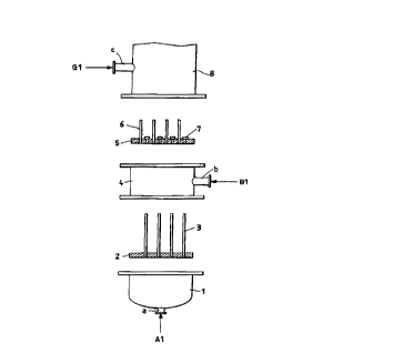
Preferred embodiments will now be described having
reference the attached drawing, wherein:
Figures 1 and 2 represenr_ a reactcr according to the
present invention, and
Figures 3 and 4 represent a detail relating to a
reactor comprising two exchange sections vertically arranged
on top of each other.
Therefore, with reference to figures l, 2, 3 and 4, the
reactor of the present i.~:vent~on comprz.ses the bottom head
(1) into which the reagent gas Zs fed, through the inlet
nozzle (a); the perforated p-Late (~); the tubes (3) for
conveying the gas t.o the distributors (7); the cylindrical
casing (4); the perforated plate (:~); the tubes of the tube-
bundle (6); the cylindrical casing (8) and the perforated
plate (9) equipped with perimat.ra-'~ s-'~ots (11) and to whose
holes the tubes or the tube-bundle (6) are fixed and also
the ducts (10) which allow the passage of the non-reacted
gas and
30

CA 02248067 2002-05-03
- 5 -
suspension.
According to a variation of the present invention,
which refers to a reactor which comprises two thermal
exchange sections, (figures 3 and 4), a double-walled
cylindrical casing (12') is fixed to the plate (9), by
means of a flanged connection, whose internal body is
divided into two substantially equal volumes by a
perforated diaphragm (13') into which the ducts (10)
pass, having a length substantially equal to the height
of the cylindrical casing (12') and which convey the
non-reacted gas and the suspension, both to the annular
chamber (15').
The lower volume of the casing (12'), below the
diaphragm (13'), is connected to the outside by one or
25 more outlet nozzles (d') through which the cooling
fluid (B2) of the reaction zone/thermal exchange (8),
is discharged. The upper volume of the casing (12'),
above the diaphragm (13'), is connected to the outside
of the reactor by one or more inlet nozzles (e')
through which the cooling fluid (B1') of the reaction
zone/thermal exchange above the casing (12') is fed.
A perforated plate (16'), equipped with perimetral
slots (18) which are symmetrical and coinciding with
the annular chamber (15'), is joined to the double-
walled casing (12') by means of a flanged connection

CA 02248067 2002-05-03
- 6 -
and the tubes of a tube-bundle (17') and possible
distributors (7') are fixed in its upper holes.
The reactor with two thermal exchange sections of
the present invention therefore comprises the cylindri-
cal casing (19), having a height equal to that of the
tube-bundle (17'), and the following end units:
- a perforated plate (20), fixed to the casing (19)
by means of a flanged connection, equipped with
symmetrical perimetral slots (21), in whose holes
the tubes of the tube-bundle (17') are fixed
below, and ducts (22) for the passage of the non-
reacted gas and suspension, above;
- a double-walled cylindrical casing (23) fixed to
the plate (20) by means of a flanged connection in
which the annular section (24} coincides with the
perimetral slots (21) of the plate (20), the
internal wall of said cylindrical casing (23) has
one or more feedthrough outlet nozzles (f') for
discharging the cooling fluid (B2');
- a perforated plate (25), joined to the double-
walled casing (23) by means of a flanged connec-
tion, equipped with perimetral slots (26) which
are symmetrical and coinciding with the annular
chamber (24), and in whose holes the ducts (22)
are fi}:ed.

CA 02248067 2002-05-03
_ 7
The reactor comprising two thermal exchange
sections of the present invention terminates with a
head (16), fixed to the plate (25) by means of a
flanged connection, containing outlet nozzles (e) for
discharging the suspension (G2) and outlet nozzles (f)
for discharging the non-reacted gas (A2) and also a
group of inclined diaphragms (17) for separating the
particles of liquid and/or solid drawn in.

Representative Drawing
A single figure which represents the drawing illustrating the invention.
Administrative Status

For a clearer understanding of the status of the application/patent presented on this page, the site Disclaimer , as well as the definitions for Patent , Administrative Status , Maintenance Fee  and Payment History  should be consulted.

Administrative Status

Title Date
Forecasted Issue Date 2002-12-24
(22) Filed 1998-10-13
(41) Open to Public Inspection 1999-04-14
Examination Requested 1999-07-09
(45) Issued 2002-12-24
Deemed Expired 2012-10-15

Abandonment History

There is no abandonment history.

Payment History

Fee Type Anniversary Year Due Date Amount Paid Paid Date
Application Fee $300.00 1998-10-13
Registration of a document - section 124 $100.00 1999-01-27
Request for Examination $400.00 1999-07-09
Maintenance Fee - Application - New Act 2 2000-10-13 $100.00 2000-10-02
Maintenance Fee - Application - New Act 3 2001-10-15 $100.00 2001-09-27
Maintenance Fee - Application - New Act 4 2002-10-14 $100.00 2002-09-30
Final Fee $300.00 2002-10-07
Maintenance Fee - Patent - New Act 5 2003-10-13 $150.00 2003-09-17
Maintenance Fee - Patent - New Act 6 2004-10-13 $200.00 2004-09-09
Maintenance Fee - Patent - New Act 7 2005-10-13 $200.00 2005-09-21
Maintenance Fee - Patent - New Act 8 2006-10-13 $200.00 2006-09-18
Maintenance Fee - Patent - New Act 9 2007-10-15 $200.00 2007-09-17
Maintenance Fee - Patent - New Act 10 2008-10-13 $250.00 2008-09-17
Maintenance Fee - Patent - New Act 11 2009-10-13 $250.00 2009-09-18
Maintenance Fee - Patent - New Act 12 2010-10-13 $250.00 2010-09-17
Owners on Record

Note: Records showing the ownership history in alphabetical order.

Current Owners on Record
AGIP PETROLI S.P.A.
INSTITUT FRANCAIS DU PETROLE
Past Owners on Record
BELMONTE, GIUSEPPE
PICCOLO, VINCENZO
Past Owners that do not appear in the "Owners on Record" listing will appear in other documentation within the application.
Documents

To view selected files, please enter reCAPTCHA code :


To view images, click a link in the Document Description column. To download the documents, select one or more checkboxes in the first column and then click the "Download Selected in PDF format (Zip Archive)" or the "Download Selected as Single PDF" button.

List of published and non-published patent-specific documents on the CPD .

If you have any difficulty accessing content, you can call the Client Service Centre at 1-866-997-1936 or send them an e-mail at CIPO Client Service Centre.


Document
Description 
Date
(yyyy-mm-dd) 
Number of pages   Size of Image (KB) 
Description 2002-05-03 7 217
Representative Drawing 1999-05-03 1 3
Abstract 1998-10-13 1 17
Description 1998-10-13 8 207
Claims 1998-10-13 6 136
Drawings 1998-10-13 4 40
Abstract 1998-12-10 1 19
Description 1998-12-10 8 227
Claims 1998-12-10 6 151
Cover Page 1999-05-03 1 39
Description 1999-11-01 8 233
Claims 2002-05-03 4 140
Cover Page 2002-11-20 1 32
Prosecution-Amendment 1999-07-09 1 34
Prosecution-Amendment 1999-11-01 3 82
Correspondence 2002-10-07 1 32
Prosecution-Amendment 2002-05-03 13 391
Prosecution-Amendment 2002-03-19 2 58
Assignment 1998-10-13 3 91
Correspondence 1998-11-04 1 35
Correspondence 1998-12-10 17 447
Assignment 1999-01-27 2 64
Correspondence 2010-08-10 1 46
Correspondence 2011-11-24 1 66