Note: Descriptions are shown in the official language in which they were submitted.
CA 02248287 1998-09-22
FAIL-SAFE COUPLING FOR A LATCH ASSEMBLY
FIELD OF INVENTION
The present invention relates to a fail-safe tubular receiving member,
preferably a coupling, for use in combination with a latch assembly for
longitudinally supporting and rotationally orienting the latch assembly in a
wellbore
at a location beneath the surface. Further, the invention relates to a fail-
safe
apparatus for longitudinally supporting and rotationally orienting a well tool
in the
wellbore, wherein the apparatus is comprised of the latch assembly for
connection
with the tool and the tubular receiving member.
BACKGROUND OF INVENTION
Current drilling technology, including directional drilling technology,
permits the drilling of conventional vertical wellbores which are
substantially
perpendicular to the ground surface, as well as deviated or non-vertical
wellbores.
Directional drilling technology also allows for branch, lateral or secondary
wellbores
to be drilled laterally from a main or primary wellbore. Lateral wellbores are
often
drilled and produced through a gap in the casing of the main wellbore. This
gap
typically comprises a window cut or milled in a section of the existing casing
string.
The lateral wellbore tends to extend laterally from the main wellbore to a
desired
location within the formation.
In order to drill and produce such lateral wellbores, it is necessary for
downhole drilling and production tools to be capable of being located and
oriented
downhole. First, the downhole tool must be capable of being located at the
desired
depth beneath the surface. In particular, the downhole tool is preferably able
to be
located at or adjacent the window in the casing for the lateral wellbore.
Second, in
order that the tool may be diverted in the desired direction, such as for the
drilling
or re-entry of the lateral wellbore, the tool is also preferably able to be
oriented
within the wellbore in a desired direction.
Conventional downhole landing systems typically include one or more
landing nipples spaced apart in a wellbore. These landing nipples provide
internal
-1-
CA 02248287 1998-09-22
profiled recesses which are compatible with the external profile of a
corresponding
lock mandrel or latch which is connectable to or forms a part of a downhole
tool.
Matching of the profiles on the landing nipple and the lock mandrel acts to
locate
the tool longitudinally within the wellbore at a desired location downhole.
However, these conventional landing systems may not provide for or permit the
downhole tool to be oriented in a desired manner relative to a lateral
wellbore.
Thus, these systems have limited application to the drilling or production of
lateral
wellbores.
For example, conventional downhole landing and locating systems are
shown in United States of America Patent No. 5,348,087 issued September 20,
1994 to
Williamson, Tr., United States of America Patent No. 4,994,345 issued July 31,
1990 to
Mashaw. Tr., United States of America Patent No. 4,457,368 issued July 3, 1984
to
Knierimen et. al., United States of America Patent No. 4,396,061 issued August
2,
1983 to Tamplen et. al., United States of America Patent No. 4,167,970 issued
September 18, 1979 to Cowan, United States of America Patent No. 4,164,977
issued
August 21, 1979 to Arendt et. al., and United States of America Patent No.
4,023,620
issued May 17, 1977 to Gazda et. al.
As stated, it is important not only to be able to establish the depth of the
downhole tool, but also to be able to establish an angular reference or
orientation
from which lateral wellbores may be drilled or selectively re-entered. United
States
of America Patent No. 4,415,205 issued November 15, 1983 to Rehm et. al.
provides
an indexing mechanism for both locating and orienting tools. More
particularly, the
indexing mechanism is comprised of an indexing dog which consists of a
protrusion
or internally projecting keys formed on the internal wall of the casing. The
protrusion extends radially inwardly from the casing for engagement with an
opening in a template associated with the downhole tool. These protrusions
thus
restrict the internal clearance or diameter of the casing and may therefore
interfere
with the work to be performed in the casing, as well as the tools which may be
passed therethrough.
European Patent Application No. 0834643 published April 8, 1998 also
provides a method and apparatus for landing and orienting downhole tools at
selected depths. More particularly, a well casing is provided with a plurality
of
-2-
CA 02248287 1998-09-22
landing and orienting joints located at selected depths. Each joint defines a
differing
internal landing profile and has a muleshoe therein. The muleshoe defines an
upwardly facing point and an orientation slot and has helical guide ramp
surfaces
extending from the point to the orientation slot. The downhole tool incudes a
plurality of landing dogs for engaging the landing profile of one of the
joints.
Further, the tool has an orientation key for guiding engagement with the
helical
guide ramp surfaces and orienting engagement with the orientation slot. Thus,
a
relatively complex structure is provided for landing and orienting the tool.
Further,
the structure provided for landing the tool is distinct or separate from the
structure
provided for orienting the tool.
United States of America Patent No. 5,579,829 issued December 3, 1996
to Comeau et. al. provides a keyless latch assembly having external surface
contours
compatible with a recessed area formed on the internal surface of a well
casing. The
recessed area is comprised of a series of grooves and slots for receiving the
latch
assembly therein. More particularly, upon the alignment of the latch assembly
longitudinally with the grooves, the latch assembly is located at a desired
depth
beneath the surface. Upon the further alignment of the latch assembly
rotationally
with the slots, the latch assembly is oriented in a desired direction.
However, the latch assembly and grooves permit the latch assembly to
be moved longitudinally in either an upwards or a downwards direction within
the
casing upon the application of further force to the latch assembly to overcome
the
engagement of the latch assembly with the grooves. Only upon the rotational
alignment of the latch assembly with the slots is the latch assembly prevented
from
moving longitudinally in a downwards direction away from the surface. Thus, it
is
possible that a downhole tool fitted with the latch assembly could be
accidentally
dropped or pushed through the recessed area, and lost downhole, in the event
the
latch assembly passes through the recessed area without aligning with the
slots.
Therefore, there is a need in the industry for a fail-safe or safety
apparatus for longitudinally supporting and rotationally orienting a well tool
in a
wellbore at a location beneath the surface. Further, there is a need for a
fail-safe or
safety tubular receiving member for use in combination with a latch assembly
to
longitudinally support and rotationally orient the latch assembly in the
wellbore.
-3-
CA 02248287 1998-09-22
More particularly, there is a need for the apparatus and the receiving member
to
prevent the longitudinal movement of a latch assembly relative to the
receiving
member in a downward direction away from the surface, such that a tool fitted
with
the latch assembly may be located at a desired depth downhole and may not be
accidentally lost downhole, while still permitting the latch assembly, and the
tool
connected therewith, to be oriented in a desired direction.
SUMMARY OF INVENTION
The present invention relates to a fail-safe or safety apparatus for
longitudinally supporting and rotationally orienting a well tool in a wellbore
at a
location beneath the surface. Further, the present invention relates to a fail-
safe or
safety tubular receiving member or coupling forming part of the wellbore
casing for
use in combination with a latch assembly to longitudinally support and
rotationally
orient the latch assembly in the wellbore.
More particularly, the present invention relates to an apparatus and a
receiving member which prevent the longitudinal movement of a latch assembly
relative to the receiving member in a downward direction away from the
surface.
Thus, the latch assembly, and any tool fitted therewith, may be located at a
desired
depth downhole and may not be accidentally pushed or dropped through the
receiving member. Further, the apparatus and the receiving member prevent the
longitudinal movement of the latch assembly through the receiving member
regardless of the orientation of the latch assembly relative to the receiving
member.
Once longitudinally landed in the receiving member, the latch assembly, and
the
tool connected therewith, may be oriented in a desired direction.
In a first aspect of the invention, the invention is comprised of a fail-
safe tubular receiving member for use in combination with a latch assembly to
longitudinally support and rotationally orient the latch assembly in a
wellbore at a
location beneath the surface, the latch assembly comprising at least one
outwardly
biased, radially movable latch member and the tubular receiving member
defining a
bore having an internal surface for receiving the latch assembly therein and a
longitudinal axis extending therethrough, wherein the improvement comprises:
-4-
CA 02248287 1998-09-22
(a) a first recessed area defined by the internal surface of the bore of the
receiving member, wherein the first recessed area defines a first
increased radial distance between the longitudinal axis of the receiving
member and the first recessed area and wherein the first recessed area is
configured so that upon longitudinal alignment of the latch member
and the first recessed area, the latch member moves radially outward
and is received in the first recessed area to support the latch assembly
longitudinally such that longitudinal movement of the latch assembly
relative to the receiving member in a downward direction away from
the surface is prevented; and
(b) a second recessed area defined by the internal surface of the bore of the
receiving member and accessible by the latch member from the first
recessed area, wherein the second recessed area defines a second
increased radial distance between the longitudinal axis of the receiving
member and the second recessed area which is greater than the first
increased radial distance and wherein the second recessed area is
configured so that upon rotational alignment of the latch member and
the second recessed area, the latch member moves radially outward and
is received in the second recessed area to orient the latch assembly
rotationally such that rotation of the latch assembly relative to the
receiving member is inhibited.
In a second aspect of the invention, the invention is comprised of a fail-
safe apparatus for longitudinally supporting and rotationally orienting a well
tool in
a wellbore at a location beneath the surface, comprising:
(a) a latch assembly for connection with the tool, the latch assembly
comprising at least one outwardly biased, radially movable latch
member;
(b) a tubular receiving member for containing within the wellbore at the
location beneath the surface, wherein the tubular receiving member
defines a bore for receiving the latch assembly therein, wherein the bore
-5-
CA 02248287 1998-09-22
defines a longitudinal axis extending therethrough and wherein the
bore has an internal surface;
(c) a first recessed area defined by the internal surface of the bore of the
receiving member, wherein the first recessed area defines a first
increased radial distance between the longitudinal axis of the receiving
member and the first recessed area and wherein the first recessed area is
configured so that upon longitudinal alignment of the latch member
and the first recessed area, the latch member moves radially outward
and is received in the first recessed area to support the latch assembly
longitudinally such that longitudinal movement of the latch assembly
relative to the receiving member in a downward direction away from
the surface is prevented; and
(d) a second recessed area defined by the internal surface of the bore of the
receiving member and accessible by the latch member from the first
recessed area, wherein the second recessed area defines a second
increased radial distance between the longitudinal axis of the receiving
member and the second recessed area which is greater than the first
increased radial distance and wherein the second recessed area is
configured so that upon rotational alignment of the latch member and
the second recessed area, the latch member moves radially outward and
is received in the second recessed area to orient the latch assembly
rotationally such that rotation of the latch assembly relative to the
receiving member is inhibited.
In the first and second aspects of the invention, the first recessed area
extends circumferentially about the entire bore of the receiving member so
that the
latch assembly is capable of rotation relative to the receiving member when
the latch
member is received in the first recessed area. Further, the second recessed
area
extends circumferentially about a portion of the bore of the receiving member
such
that when the latch member is received in the first recessed area the latch
assembly
may be rotated relative to the receiving member to align the latch member
rotationally with the second recessed area.
-6-
CA 02248287 1998-09-22
The first recessed area may have any shape, dimensions or
configuration compatible with the latch assembly and the intended function of
the
first recessed area as described herein. More particularly, the first recessed
area may
have any shape, dimensions or configuration which permits the latch member to
move radially outward for receipt in the first recessed area upon the
longitudinal
alignment of the latch member and the first recessed area and which prevents
the
downward movement of the latch assembly when the latch member is received in
the first recessed area. In the preferred embodiment, the first recessed area
is
comprised of at least one groove defined by the bore of the receiving member
extending about the entire circumference of the bore.
The second recessed area may also have any shape, dimensions or
configuration compatible with the latch assembly and the intended function of
the
second recessed area as described herein. More particularly, the second
recessed area
may have any shape, dimensions or configuration which permits the latch member
to move radially outward for receipt in the second recessed area upon the
rotational
alignment of the latch member and the second recessed area and which inhibits
the
rotation of the latch assembly relative to the receiving member when the latch
member is received in the second recessed area. In the preferred embodiment,
the
second recessed area is comprised of at least one slot defined by the bore of
the
receiving member extending only partially about the circumference of the bore.
Further, the latch member comprises an external surface. The external
surface of the latch member is compatible with both the first and second
recessed
areas such that the latch member may be received therein as described above.
More
particularly, the external surface of the latch member is preferably comprised
of a
first contour. The first recessed area is compatible with the first contour
such that
longitudinal movement of the latch member relative to the receiving member in
a
downward direction away from the surface is prevented when the latch member is
received in the first recessed area. Further, the external surface of the
latch member
is also preferably comprised of a second contour. The second recessed area is
compatible with the second contour such that rotational movement of the latch
member relative to the receiving member is inhibited when the latch member is
received in the second recessed area.
CA 02248287 1998-09-22
In the preferred embodiment, the first contour is comprised of a
downwardly directed shoulder on the latch member. Further, the first recessed
area
is comprised of an upwardly directed shoulder in the first recessed area for
engagement with the downwardly directed shoulder of the latch member upon
receipt of the latch member in the first recessed area. The upwardly directed
shoulder and the downwardly directed shoulder may have any shapes or
configurations able to prevent the longitudinal movement of the latch member
relative to the receiving member upon the engagement of the upwardly and
downwardly directed shoulders. However, preferably, the downwardly directed
shoulder of the latch member is substantially square and the upwardly directed
shoulder of the first recessed area is substantially square so that when the
latch
member is received in the first recessed area the downwardly directed shoulder
engages the upwardly directed shoulder to prevent longitudinal movement of the
latch member relative to the receiving member.
As well, in the preferred embodiment, the second contour is comprised
of sidewardly directed latch shoulders on the latch member. Further, the
second
recessed area is comprised of sidewardly directed recess shoulders in the
second
recessed area. The sidewardly directed latch shoulders and the sidewardly
directed
recess shoulders may have any shapes or configurations able to inhibit the
rotational
movement of the latch member relative to the receiving member upon the
engagement of the respective sidewardly directed shoulders. However,
preferably,
the sidewardly directed latch shoulders of the latch member are substantially
square
and the sidewardly directed recess shoulders of the second recessed area are
substantially square so that when the latch member is received in the second
recessed area the sidewardly directed latch shoulders engage the sidewardly
directed
recess shoulders to inhibit rotational movement of the latch member relative
to the
receiving member.
The latch assembly is comprised of at least one latch member for receipt
in the first and second recessed areas. However, preferably, the latch
assembly is
comprised of a plurality of latch members. In the preferred embodiment, the
latch
assembly is comprised of four latch members. Where the latch assembly is
comprised of greater than one latch member, the latch members are configured
on
the latch assembly in a pattern and the second recessed area is configured to
be
_g_
CA 02248287 1998-09-22
compatible with the pattern of latch members so that rotational alignment of
one
latch member with the second recessed area will result in rotational alignment
of all
of the latch members with the second recessed area. Further, the rotational
alignment of the latch members with the second recessed area is preferably
achieved
at a single rotational orientation of the latch assembly relative to the
receiving
member.
BRIEF DESCRIPTION OF DRAWINGS
Embodiments of the invention will now be described with reference to
the accompanying drawings, in which:
Figure 1 is a pictorial view, partly in longitudinal section, of a preferred
receiving member of the within invention for use in combination with a latch
assembly, showing a first recessed area comprised of a plurality of grooves
and
showing a second recessed area comprised of a plurality of slots arranged in
four
positions;
Figure 2 is a pictorial view of the receiving member shown in Figure 1,
showing the four slot positions of the second recessed area in greater detail;
Figure 3 is a cross-sectional view of the receiving member taken along
line 3 - 3 of Figure 1;
Figure 4 is a longitudinal sectional view of the receiving member as
shown in Figure 1; and
Figures 5a, 5b, 5c and 5d are pictorial views of four latch members
comprising the preferred latch assembly of the within invention, showing the
external surfaces of the latch members in detail.
DETAILED DESCRIPTION
Referring to Figures 1 - 5, the within invention is directed at a fail-safe
apparatus for longitudinally supporting and rotationally orienting a well tool
in a
-9-
CA 02248287 1998-09-22
wellbore at a location beneath the ground surface. The apparatus is comprised
of a
receiving member (20) for containing in the wellbore at the desired location
beneath
the surface and a latch assembly (22) for connection with the tool. Further,
the
within invention is directed at an improved fail-safe receiving member (20)
for use
in combination with a latch assembly (22) to longitudinally support and
rotationally
orient the latch assembly (22) in the wellbore at the desired subsurface
location. The
latch assembly (22) is connectable with a well tool and may be passed through
the
wellbore to the location of the receiving member (20) in the wellbore. Thus, a
description of the preferred apparatus necessarily includes a description of
the
preferred receiving member (20).
The apparatus and the receiving member (20) of the within invention
are provided primarily to function as a fail-safe or safety device or
mechanism.
Specifically, the apparatus and the receiving member (20) prevent the passage
of a
well tool fitted with the latch assembly (22) past or through the receiving
member
(20) such that the tool cannot be lost downhole. Thus, the latch assembly (22)
may
not be dropped or pushed through the receiving member (20). Further, the
receiving member (20) is configured such that the latch assembly (22) is
prevented
from passing through it regardless of the orientation of the latch assembly
(22) in the
wellbore.
Once the latch assembly (22) is moved through the wellbore and
received longitudinally within the receiving member (20) at the desired
location
beneath the surface, the latch assembly (22) and the tool connected therewith
are
longitudinally supported in the wellbore by the receiving member (20). As the
receiving member (20) is located at a designed and pre-measured depth in the
wellbore, the receipt of the latch assembly (22) in the receiving member (20)
also acts
as a depth indicator.
Further, the apparatus and the receiving member (20) also preferably
function as an orienting mechanism. Specifically, once the latch assembly (22)
is
received longitudinally within the receiving member (20), the latch assembly
(22)
may be rotated relative to the receiving member (20) to orient the latch
assembly
(22), and thus the connected well tool, in a desired direction. In this
regard, the
receiving member (20) is configured such that the latch assembly (22) is
inhibited
-10-
CA 02248287 1998-09-22
from further rotation within the receiving member (20) once the latch assembly
(22)
achieves a designed and pre-measured orientation.
As the apparatus and receiving member (20) may be used to perform
both a locating and an orienting function, the apparatus and the receiving
member
(20) have been found to be of particular use in the drilling and production of
lateral
wellbores. In this case, a secondary, branch or lateral wellbore extends
laterally from
a primary or main wellbore. Such lateral wellbores are often drilled or
produced
through a gap or window in the casing or wall of the main wellbore. Thus, the
receiving member (20) may be used to locate and orient the latch assembly (22)
and
the tool connected therewith relative to the window.
As stated, the apparatus is comprised of the latch assembly (22), while
the improved receiving member (20) is for use in combination with the latch
assembly (22). Any conventional latch assembly (22) compatible with the
receiving
member (20), as described herein, may be used. Further, the latch assembly
(22) is
capable of being run downhole through the wellbore to the desired location
beneath
the surface for receipt in the tubular receiving member (20). As well, the
latch
assembly (22) is connectable with a desired well tool in that the latch
assembly (22)
may either be attachable or fittable with a desired well tool or it may form
an integral
part of the well tool. Where the latch assembly (22) is attached or fitted
with the well
tool, the latch assembly (22) may be attached to the well tool by any
conventional
fasteners or mechanisms for attachment, such as by a threaded connection
between
the latch assembly (22) and the well tool. The latch assembly (22) and tool
may be
placed downhole using any conventional equipment or methods for placing tools
downhole. For instance, the latch assembly (22) and tool may be lowered in the
wellbore on a drill string.
Referring to Figures 5a - 5d, the latch assembly (22) is comprised of at
least one outwardly biased, radially movable latch member (24). However,
preferably, the latch assembly (22) is comprised of two or more latch members
(24).
Any number of latch members (24) capable of securely or firmly engaging the
receiving member (20) as described below may be used. In the preferred
embodiment, the latch assembly (22) is comprised of four latch members (24),
as
shown in Figures 5a - 5d.
-11-
CA 02248287 1998-09-22
In the preferred embodiment, with the exception of the number of latch
members (24) comprising the latch assembly (22), the latch assembly (22) is
comprised of a conventional latch assembly as shown and described in United
States
of America Patent No. 5,579,829 issued December 3, 1996 to Comeau et. al.
Specifically, the improved receiving member (20) of the within invention is
designed for use with the latch assembly of Comeau et. al. However, as stated,
the
latch assembly (22) of the within invention may be comprised of any number of
latch members (24) other than the three latch members (24) shown in Comeau et.
al.
In particular, the preferred embodiment of the latch assembly (22) of the
within
invention is comprised of four latch members (24). As a result, the specific
pattern
or contours of each latch member (24) differs somewhat from that described in
Comeau et. al.
More particularly, in the preferred embodiment, the latch assembly (22)
defines a longitudinal axis. Further, referring to Figures 5a - 5d, each of
the latch
members (24) has a first end (26), an opposing second end (28) and a
longitudinal axis
extending therebetween. Further, each latch member (24) has an external
surface
(30), for engaging the receiving member (20), and an opposing internal surface
(32).
As well, the external surface (30) of each latch member (24) is comprised of a
first
contour (34) and a second contour (36), the purposes of which are further
described
below. In the preferred embodiment, the latch members (24) are spaced about
the
latch assembly (22) such that the longitudinal axes of the latch members (24)
are
substantially parallel with the longitudinal axis of the latch assembly (22).
Further,
the external surfaces (30) of the latch members (24) face outwards, away from
the
latch assembly (22),
In addition, each of the latch members (24) is movably mounted or
connected with the latch assembly (22) such that each latch member (24) is
movable
radially with respect to the latch assembly (22). In other words, each latch
member
(24) is reciprocally movable away from and towards the longitudinal axis of
the latch
assembly (22). Any conventional mechanism, apparatus or structure for movably
mounting the latch members (24) in the described manner may be used. However,
the latch members (24) must be capable of moving inwardly, towards the
longitudinal axis of the latch assembly (22), for a sufficient distance to
permit the
-12-
CA 02248287 1998-09-22
latch assembly (22) to be moved through the wellbore and the receiving member
(20)
without damaging the latch members (22). Conversely, the latch members (24)
must
be capable of moving outwardly, away from the longitudinal axis of the latch
assembly (22), for a sufficient distance to achieve the necessary engagement
of the
latch members (24) with the receiving member (20), as described below, to
prevent
longitudinal movement and to inhibit rotational movement of the latch assembly
(22) relative to the receiving member (20).
As well, each of the latch members (24) is preferably outwardly biased.
In other words, each of the latch members (24) tends to be urged away from the
longitudinal axis of the latch assembly (22). Thus, when the latch assembly
(22) is
being passed through the wellbore to the location of the receiving member
(20), the
external surfaces (30) of the latch members (24) are urged towards the
wellbore.
When the latch assembly (22) is received in the receiving member (20), the
external
surfaces (30) of the latch members (24) are urged towards the receiving member
(20).
The latch members (24) may be outwardly biased by any conventional mechanism,
apparatus or structure, such as by one or more springs acting against or upon
the
internal surfaces (32) of the latch members (24). Further, the specific urging
mechanism is selected to provide a secure or firm engagement between the latch
members (24) and the receiving member (20) when the latch members (24) are
received therein.
The tubular receiving member (20) is containable within the wellbore at
the desired location beneath the surface. As indicated previously, the
location or
depth of the receiving member (20) is preferably pre-selected or pre-measured
so that
the receiving member (20) may act as a depth locator when the latch assembly
(22) is
received therein. Further, as the receiving member (20) is configured to act
as a fail-
safe mechanism, and it will thus prevent any tool fitted with the latch
assembly (22)
from passing therethrough, the receiving member (20) is preferably located at
the
greatest depth downhole at which it is desired to locate and orient a well
tool. For
instance, the receiving member (20) of the within invention is preferably
located
downhole of the window or gap in the wellbore located the furthest from the
surface.
-13-
CA 02248287 1998-09-22
Further, as indicated previously, the circumferential orientation of the
receiving member (20) is also preferably pre-selected or pre-measured so that
the
orientation of the latch assembly (22) and the attached tool are known. For
instance,
the latch assembly (22) and the tool are typically oriented relative to the
window or
gap in the wellbore, and thus the lateral wellbore extending therefrom.
The tubular receiving member (20) may be comprised of any tubular
structure capable of being placed within the wellbore and able to receive the
latch
assembly (22) therein. However, preferably, the receiving member (20) is
associated
with the casing of the wellbore such that the receiving member (20) is
continuous
therewith. Further, preferably, the receiving member (20) does not obstruct or
otherwise interfere significantly with the passage of equipment or fluids
through the
casing during the drilling or production of the wellbore. For instance, the
receiving
member (20) may be comprised of a portion of the casing of the wellbore such
that
the receiving member (20) is integrally formed therewith. However, in the
preferred
embodiment, the receiving member (20) is comprised of a casing coupling
connectable with the casing of the wellbore.
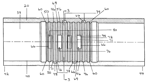
As shown in Figures 1 - 4, the receiving member (20) is tubular in
configuration such that it defines a bore (38), having an internal surface
(40), for
receiving the latch assembly (22) therein. The bore (38) extends from a first
end (42)
to a second end (44) of the receiving member (20) and defines a longitudinal
axis
extending therethrough. When the latch assembly (22) is located within the
receiving member (20), the external surfaces (30) of the latch members (24)
are urged
towards the internal surface (40) of the bore (38) of the receiving member
(20).
Referring to Figures 1 and 4, the internal surface (40) of the bore (38) of
the receiving member (20) defines a first recessed area (46) and a second
recessed area
(48). The first and second recessed areas (46, 48) are specifically configured
to align
with and receive the latch members (24). More particularly, when aligned with
the
first and second recessed areas (46, 48), the latch members (24) move radially
outward
such that the external surfaces (30) of the latch members (24) move towards
the
internal surface (40) of the bore (38) of the receiving member (20) within the
recessed
areas (46, 48).
-14-
CA 02248287 1998-09-22
The first recessed area (46) defines a first increased radial distance
between the longitudinal axis of the receiving member (20) and the portion of
the
internal surface (40) of the bore (38) defining the first recessed area (46).
The first
recessed area (46) is configured so that upon the longitudinal alignment of
the latch
member (24) and the first recessed area (46), the latch member (24) moves
radially
outward, as a result of the increased radial distance, and is received in the
first
recessed area (46) to support the latch assembly (22) longitudinally. Further,
the first
recessed area (46) is configured such that once the latch assembly (22) is
supported
longitudinally in the receiving member (20), further longitudinal movement of
the
latch assembly (22) relative to the receiving member (20) in a downward
direction,
away from the ground surface or further downhole, is prevented.
As well, in order that the latch assembly (22) may be oriented within the
receiving member (20) once it is longitudinally supported thereby, the first
recessed
area (46) is configured to permit the rotation of the latch assembly (22)
relative to the
receiving member (20) when the latch members (24) are received in the first
recessed
area (46).
The first recessed area (46) may have any shape or configuration having
the above-noted characteristics or which is capable of performing the above-
noted
functions or purposes. However, in the preferred embodiment, the first
recessed
area (46) extends circumferentially about the entire bore (38) of the
receiving
member (20) so that the latch assembly (22) is capable of rotation relative to
the
receiving member (20) when the latch members (24) is received in the first
recessed
area (46).
More particularly, referring to Figures 1 and 4, the first recessed area (46)
is preferably comprised of at least one groove (50) defined by the bore (38)
of the
receiving member (20) extending about the entire circumference of the bore
(38).
However, the first recessed area (46) may be comprised of any number of
grooves (50)
as required to be compatible with the latch members (24) and the pattern or
contours
of the external surfaces (30) thereof.
As stated above, the external surface (30) of each latch member (24) is
comprised of a first contour (34). The first recessed area (46), and in
particular the
-15-
CA 02248287 1998-09-22
grooves (50), are configured to be compatible with the first contour (34) of
each latch
member (24) such that the first contour (34) is received in the first recessed
area (46)
and longitudinal movement of the latch member (24) relative to the receiving
member (20) in a downward direction, away from the surface or further
downhole,
is prevented when the latch member (24) is received in the first recessed area
(46).
The first contour (34) of each latch member (24) may have any shape or
configuration having the above-noted characteristics or which is capable of
performing the above-noted functions or purposes. However, as shown in Figures
5a - 5d, in the preferred embodiment, the external surface (30) of each latch
member
(24) defines at least one, and preferably a plurality, of projections (52) or
protrusions
extending away from the external surface (30) for engagement with the
receiving
member (20). Preferably, the projections (52) comprise the first contour (34)
for
preventing the downward movement of the latch member (24) relative to the
receiving member (20). More particularly, each of the projections (52) has a
downwardly directed shoulder (54). At least one of the downwardly directed
shoulders (54) of the latch member (24) is configured to prevent the downward
movement of the latch member (24) relative to the receiving member (20).
Further, as stated, the first recessed area (46) is compatible with the first
contour (34), and thus, is compatible with the projections (52) and the
downwardly
directed shoulders (54) of the latch members (24). Thus, the first recessed
area (46) is
preferably comprised of at least one upwardly directed shoulder (56) for
engaging at
least one downwardly directed shoulder (54) of the latch member (24) upon
receipt of
the latch member (24) in the first recessed area (46). More particularly, at
least one of
the grooves (50) defined by the first recessed area (46) preferably includes
or defines
the upwardly directed shoulder (56).
The downwardly directed shoulders (54) of the latch member (24) and
the upwardly directed shoulders (56) of the first recessed area (46) may have
any
shape or configuration so long as the engagement of at least one downwardly
directed shoulder with a corresponding upwardly directed shoulder prevents
longitudinal movement of the latch member (24) in a direction downhole
relative
to the receiving member (20). However, preferably, at least one downwardly
directed
shoulder (54) of the latch member (24) is substantially square (58) in shape
and at
-16-
CA 02248287 1998-09-22
least one corresponding upwardly directed shoulder (56) of the first recessed
area (46)
is substantially square (60) in shape. As a result, when the latch member (24)
is
received in the first recessed area (46), the square downwardly directed
shoulder (58)
engages the square upwardly directed shoulder (60) to prevent longitudinal
movement of the latch member (24) relative to the receiving member (20).
Referring to Figures 5a - 5d, in the preferred embodiment, each latch
member (24) includes five projections (52), each having a downwardly directed
shoulder (54). Of these downwardly directed shoulders (54), two are square
(58) in
shape and are located adjacent or in proximity to the first and second ends
(26, 28) of
the latch member (24) respectively as shown in Figures 5a - 5d. However, any
other
location compatible with their intended function may be used. Further, the
locations of the square downwardly directed shoulders (58) are the same on
each of
the latch members (24). Similarly, referring to Figures 1 and 4, in the
preferred
embodiment, the grooves (50) of the first recessed area (46) corresponding to
the
locations of the square downwardly directed shoulders (58) of the latch member
(24)
define compatible square upwardly directed shoulders (60) for engagement
therewith.
Referring to Figures 5a - 5d, each of the projections (52) also has an
upwardly directed shoulder (62) opposite the downwardly directed shoulder
(54). As
well, referring to Figures 1 and 4, each of the grooves (50) of the first
recessed area
(46) also has a downwardly directed shoulder (64) opposite the upwardly
directed
shoulder (56). Preferably, the upwardly directed shoulder (62) of the latch
member
(24) and the corresponding downwardly directed shoulder (64) of the first
recessed
area (46) are compatibly tapered or sloped so that the latch assembly (22) may
be
moved in an upward direction towards the surface relative to the receiving
member
(20) when the latch member (24) is received in the first recessed area (46).
Specifically, as a force is applied to the latch assembly (22) in an upwards
direction,
the upwardly directed shoulder (62) of the latch member (24) moves along the
downwardly directed shoulder (64) of the first recessed area (46), which
causes the
latch member (24) to move radially inward so permit the longitudinal movement
of
the latch assembly (22) relative to the receiving member (20). This design is
preferable where the removal of the latch assembly (22), and the tool
connected
therewith, from the wellbore is either required or is otherwise desirable.
-17-
CA 02248287 1998-09-22
Referring to Figures 1 - 4, the internal surface (40) of the bore (38) of the
tubular receiving member (20) also defines the second recessed area (48). The
second
recessed area (48) is accessible by the latch member (24) from the first
recessed area
(46). In other words, the latch member (24) is permitted access to the second
recessed
area (48) when it is received in the first recessed area (46). As a result,
the latch
assembly (22) may be oriented within the receiving member (20) once it is
longitudinally supported by the first recessed area (46).
The second recessed area (48) defines a second increased radial distance
between the longitudinal axis of the receiving member (20) and the portion of
the
internal surface (40) of the bore (38) defining the second recessed area (48).
Further,
the second recessed area (48) is configured so that the second increased
radial
distance is greater than the first increased radial distance of the first
recessed area
(46). Further, the second recessed area (48) is configured so that upon the
rotational
alignment of the latch member (24) and the second recessed area (48), the
latch
member (24) moves radially outward, as a result of the second increased radial
distance, and is received in the second recessed area (48) to orient the latch
assembly
(22) rotationally. Further, the second recessed area (48) is configured such
that once
the latch assembly (22) is rotationally oriented relative to the receiving
member (20)
in the pre-measured direction or orientation, further rotation of the latch
assembly
relative to the receiving member (20) is inhibited.
In addition, upon the rotational alignment of the latch members (24)
with the second recessed area (48) and receipt of the latch members (24)
therein, the
engagement of the square downwardly directed shoulder (58) of the latch
members
(24) and the square upwardly directed shoulders (60) of the first recessed
area (46)
may be enhanced in order to facilitate or further provide for the longitudinal
support of the latch assembly (22) in the receiving member (20). For instance,
the
area of contact between the square downwardly directed shoulder (58) of the
latch
members (24) and the square upwardly directed shoulders (60) of the first
recessed
area (46) may be increased.
The second recessed area (48) may have any shape or configuration
having the above-noted characteristics or which is capable of performing the
above-
-18-
CA 02248287 1998-09-22
noted functions or purposes. However, in the preferred embodiment, the second
recessed area (48) extends circumferentially about a portion of the bore (38)
of the
receiving member (20) such that when the latch member (24) is received in the
first
recessed area (46) the latch assembly (22) may be rotated relative to the
receiving
member (20) to align the latch member (24) rotationally with the second
recessed
area (48).
More particularly, referring to Figures 1 -4, the second recessed area (48)
is preferably comprised of at least one slot (66) defined by the bore (38) of
the
receiving member (20) extending only partially about the circumference of the
bore
(38). However, the second recessed area (48) may be comprised of any number of
slots (66) as required to be compatible with the latch members (24) and the
pattern or
contours of the external surfaces (30) thereof.
As stated above, the external surface (30) of each latch member (24) is
also comprised of a second contour (36). The second recessed area (48), and in
particular the slots (66), are configured to be compatible with the second
contour (36)
of each latch member (24) such that the second contour (36) is receivable in
the
second recessed area (48) and rotational movement of the latch member (24)
relative
to the receiving member (20) is inhibited when the latch member (24) is
received in
the second recessed area (48).
The second contour (36) of each latch member (24) may have any shape
or configuration having the above-noted characteristics or which is capable of
performing the above-noted functions or purposes. However, as stated above and
as
shown in Figures 5a - 5d, in the preferred embodiment, the external surface
(30) of
each latch member (24) defines at least one, and preferably a plurality, of
the
projections (52) for engagement with the receiving member (20). Preferably,
the
projections (52) comprise the second contour (36) for preventing the
rotational
movement of the latch member (24) relative to the receiving member (20) once
the
latch member (24) is aligned with the second recessed area (48). More
particularly,
each of the projections (52) has a pair of opposing sidewardly directed latch
shoulders
(68). The sidewardly directed latch shoulders (68) of at least one of the
projections
(52) of the latch member (24) are configured to inhibit the rotational
movement of
the latch member (24) relative to the receiving member (20).
-19-
CA 02248287 1998-09-22
Further, as stated, the second recessed area (48) is compatible with the
second contour (36), and thus, is compatible with the projections (52) and the
sidewardly directed latch shoulders (68). Thus, as shown in Figure 3, the
second
recessed area (48) is preferably comprised of a compatible pair of sidewardly
directed
recess shoulders (70) for engaging at least one pair of the sidewardly
directed latch
shoulders (68) upon receipt of the latch member (24) in the second recessed
area (48).
More particularly, at least one of the slots (66) defined by the second
recessed area (48)
preferably includes or defines the sidewardly directed recess shoulders (70).
The sidewardly directed latch shoulders (68) and the corresponding
sidewardly directed recess shoulders (70) may have any shape or configuration
so
long as the engagement of at least one pair of sidewardly directed latch
shoulders (68)
with a corresponding pair of sidewardly directed recess shoulders (70)
inhibits
rotational movement of the latch member (24) relative to the receiving member
(20). For instance, the sidewardly directed latch and recess shoulders (68,
70) may be
tapered or sloped such that rotational movement is inhibited, but not
completely
prevented. However, although the rotational movement need only be inhibited in
order to orient the latch assembly (22) and the connected tool, the shoulders
(68, 70)
may be configured, where required or desired, to completely prevent any
relative
rotational movement of the latch assembly (22) and the receiving member (20)
when
the latch member (24) is aligned with the slots (66).
Preferably, at least one pair of sidewardly directed latch shoulders (68)
are substantially square in shape and at least one corresponding pair of
sidewardly
directed recess shoulders (70) are substantially square in shape. As a result,
when the
latch member (24) is received in the second recessed area (48), the square
sidewardly
directed latch shoulders (68) engages the square sidewardly directed recess
shoulders
(70) to prevent rotational movement of the latch member (24) relative to the
receiving member (20). Referring to Figures 5a - 5d, in the preferred
embodiment,
each projection (52) of the latch member (24) has square sidewardly directed
latch
shoulders (68). Similarly, referring to Figure 3, in the preferred embodiment,
the
slots (66) of the second recessed area (48) each define compatible square
sidewardly
directed recess shoulders (70) for engagement therewith.
-20-
CA 02248287 1998-09-22
Further, in addition to the sidewardly directed recess shoulders (70),
each slot (66) includes an upper surface (71) and a lower surface (72) as
shown in
Figures 1, 2 and 4. The upper and lower surfaces (71, 72) may have any shape
or
configuration. For instance, the upper and lower surfaces (71, 72) may be
sloped or
tapered. However, in the preferred embodiment, as shown in Figures 1, 2 and 4,
the
upper and lower surfaces (71, 72) are also substantially square in shape.
Where the latch assembly (22) is comprised of a plurality of latch
members (24), as in the preferred embodiment, the latch members (24) are
further
configured on the latch assembly (22) in a pattern. In the preferred
embodiment, the
latch members (24) are about equidistantly spaced about the latch assembly
(22).
Further, in this instance, the second recessed area (48) is configured to be
compatible
with the pattern of the latch members (24) so that the rotational alignment of
one
latch member (24) with the second recessed area (48) will result in the
rotational
alignment of all of the latch members (24) with the second recessed area (48).
In the
preferred embodiment as shown in Figure 3, the slots (66) comprising the
second
recessed area (48) are thus about equidistantly spaced about the bore (38) of
the
receiving member (20) to align with or complement the pattern of the latch
members (24).
Further, the projections (52) on the latch members (24) are preferably
configured in a further pattern, compatible with a complementary pattern of
slots
(66) formed in the bore (38) of the receiving member (20), so that the
rotational
alignment of the latch members (24) with the second recessed area (48), and in
particular the slots (66), may be achieved at a single rotational orientation
of the
latch assembly (22) relative to the receiving member (20).
More particularly, in the preferred embodiment, at least one of the
projections (52) on each latch member (24) acts as, or performs the function
of, an
orienting projection (73). The location or pattern of the orienting projection
(73) or
projections (73) on each latch member (24) differs from the location or
pattern of the
orienting projection (73) or projections (73) on each of the other latch
members (24).
In the preferred embodiment, each of the latch members (24) has two orienting
projections (73) which are located in the pattern illustrated in Figures 5a -
5d for each
of the four latch members (24) respectively. The second recessed area (48),
and in
-21-
CA 02248287 1998-09-22
particular the slots (66), are configured to be compatible with the latch
members (24)
such that the orienting projections (73) are receivable therein. Further, the
slots (66)
are configured so that the rotational alignment of the orienting projections
(73) of
one latch member (24) with the corresponding slots (66) will result in the
rotational
alignment of all of the latch members (24) with their respective corresponding
slots.
Finally, the slots (66) are configured so that the rotational alignment of the
orienting
projections (73) with the slots (66) may only be achieved at a single
rotational
orientation of the latch assembly (22) relative to the receiving member (20).
In the preferred embodiment, the slots (66) are configured in a
compatible pattern with the latch members (24) as illustrated in Figures 1 -
3. More
particularly, the second recessed area (48) is comprised of four slot
positions (74, 76,
78, 80) compatible with the latch members shown in Figures 5a, 5b, 5c and 5d
respectively. As a result, upon the rotational alignment of the latch members
(24)
with the second recessed area (48) at the pre-selected or pre-measured
orientation of
the latch assembly (22) relative to the receiving member (20), the latch
member (24)
shown in Figure 5a is received in slot position one (74), the latch member
(24)
shown in Figure 5b is received in slot position two (76), the latch member
(24)
shown in Figure 5c is received in slot position three (78) and the latch
member (24)
shown in Figure 5d is received in slot position four (80).
To use the within invention, the receiving member (20) is placed in the
wellbore at a pre-determined and pre-measured depth in the wellbore. The latch
assembly (22) is then lowered through the wellbore longitudinally to the
location of
the receiving member (20) where the latch assembly (22) is received within the
bore
(38) of the receiving member (20). Upon further movement of the latch assembly
(22) in a downward direction, the latch members (24) of the latch assembly
(22) are
longitudinally aligned with the grooves (50) comprising the first recessed
area (46).
Upon the longitudinal alignment of the latch members (24) and the first
recessed
area (46), the latch members (24) move radially outward and are received in
the first
recessed area (46) as a result of the first increased radial distance of the
first recessed
area (46) in order to support the latch assembly (22) longitudinally such that
further
longitudinal movement of the latch assembly (22) relative to the receiving
member
(20) in a downward direction away from the surface is prevented. More
particularly,
the further longitudinal movement is prevented by the engagement of the square
-22-
CA 02248287 1998-09-22
downwardly directed shoulders (58) of the latch members (24) with the square
upwardly directed shoulders (60) of the first recessed area (46). Typically,
the
engagement of the latch members (24) with the grooves (50) will be detectable
at the
surface as further downward movement will be prevented despite an increase in
the
force being applied.
Once the latch members (24) are longitudinally aligned with the first
recessed area (46), the latch assembly (22) is rotated about its longitudinal
axis within
the receiving member (20) until such time that the latch members (24) are
rotationally aligned with the slots (66) comprising the second recessed area
(48).
Upon the rotational alignment of the latch members (24) with the second
recessed
area (48), the latch members (24) move further radially outward and are
received in
the second recessed area (48) as a result of the second increased radial
distance of the
second recessed area (48) in order to orient the latch assembly (22)
rotationally such
that rotation of the latch assembly (22) relative to the receiving member (20)
is
inhibited. More particularly, further rotational movement is inhibited by the
engagement of the sidewardly directed latch shoulders (68) of the latch
members (24)
with the sidewardly directed recess shoulders (70) of the second recessed area
(48).
Typically, the engagement of the latch members (24) and the slots (66) will be
detected at the surface by a sharp increase in the amount of torque being
applied to
rotate the latch assembly (22).
In order to remove the latch assembly (22) from the receiving member
(20), a force is applied to the latch assembly (22) in an upwards direction.
As a result,
the upwardly directed shoulders (62) of the latch member (24) move along the
downwardly directed shoulders (64) of the first recessed area (46) and the
upper
surface (71) of the slots (66) of the second recessed area (48), which causes
the latch
member (24) to move radially inward to permit the longitudinal movement of the
latch assembly (22) relative to the receiving member (20). Any conventional
apparatus or process may be used for removing the latch assembly (22), and the
tool
connected therewith, from the wellbore.
-23-