Note: Descriptions are shown in the official language in which they were submitted.
CA 0224844~ 1998-09-2~
583P06CA
SYSTEM AND METHOD FOR DECRYPTION IN THE SYMBOL DOMAIN
FIELD OF THE INVENTION
This invention relates to a system and a method
for decryption of an encrypted stream of data carrying
any of voice, data and signaling messages in
communication systems.
BACKGROUND TO THE INVENTION
Encryption in wireless services has become
important in order to prevent cellular phone fraud, to
enhance electronic commerce and to support personal
privacy. Standards for mobile telephony have been
established to include the requirement of voice
ciphering for voice privacy as well as signaling message
and data encryption, for example in CDMA (IS-95), GSM,
(ETSI GSM 03.20 and GSM 03.21) and TDMA standard IS-
136(2).
Various methods have been proposed to achieve
the requirement of these standards. However, the
various key and mask generation proposals for achieving
the voice ciphering and message/data encryption are
different from each other. All, so far, however utilize
applying a mask bit stream to the information bit stream
via an exclusive-OR (XOR) operation.
The standard IS-136 includes a figure as shown
in Figure 1. A speech encoder 1 outputs 77 class-l and
82 class-2 bits. The 12 most perceptually significant
bits of the class-l bits are applied to a 7 bit cyclic
redundancy count (CRC) computation process 3 for
determination of a value to be used in the receiver for
error detection. The 77 class-l bits and the 7 CRC
bits, as well as 5 tail bits are applied to a rate ~
convolutional coder 5 for channel encoding, producing
178 coded class-1 bits. Those coded class-l bits and
the 82 class-2 bits are applied to a voice cipher
CA 0224844~ 1998-09-2~
circuit 7, which produces a 260 bit bit-stream. After
passing through a 2-slot interweaver 9, the signal is
applied to a modulator for transmission (not shown).
It should be noted that the voice ciphering is
performed after rate ~ convolutional coding of the
speech signal, and before modulation. Encryption is
performed in the voice cipher circuit 7 by applying a
mask to the voice bit stream via an XOR operation, bit
by bit. By the term "circuit" herein is meant either or
both of hardware and process, which may include
software.
After transmission of the encrypted signal via
e.g. a wireless medium, it is received by a receiver.
In the receiver, a system which processes the signal in
a manner opposite to the system shown in Figure 1 is
used. It should be noted that the received signal is
demodulated, deciphered, and then channel decoded before
being sent to a speech decoder. The information
sequence is represented as bits (referred to below as
bit-wise operation) before being deciphered because the
XOR operation and the mask bit stream is required to be
used. Thus, bit-wise operation is used before
modulation in the transmitter and right after
demodulation in the receiver. This is a major roadblock
preventing soft-decision decoding from being used for
this application, for the following reasons.
Figure 2 illustrates the encryption and
decryption technique in the prior art system in more
detail. A data bit stream is received by a channel
encoder 11, and the stream of encoded data bits is
applied to an XOR circuit 13 with a mask bit stream.
The resulting encrypted data bit stream is applied to a
modulator 15 (assumed herein to include a transmitter)
to a wireless medium 17.
CA 0224844~ 1998-09-2~
The signal is received and demodulated in a
demodulator l9 of a receiver, which applies the
encrypted bit stream to a decryption circuit 2l,
typically comprised of an XOR circuit, with a
corresponding mask bit stream as was used in the
encryption circuit. The resulting decrypted signal is
applied to a hard decision decoder 23, from which a
decoded bit stream is provided as an output signal.
In general, channel decoding can be performed in
either of two ways, namely hard decision decoding and
soft decision decoding. Usually analog samples output
from the demodulator can be quantized and then decoding
is performed digitally. In the extreme case in which
each sample corresponding to a single bit of a code word
is quantized to two levels, i.e. 0 or l, the demodulator
is said to make a hard decision and the channel decoder
that works with this kind of input is said to perform
hard decision decoding.
On the other hand, if the quantization is more
than two levels, the resulting quantized samples are
called soft symbols, or simply, symbols. The channel
decoder that makes use of the information as soft
symbols is said to perform soft decision decoding.
Hard decision decoding (SDD) has the advantage
of less computational complexity due to the bit-wise
operation. However, for the same reason some useful
information is lost during quantization and therefore it
does not perform very well under certain circumstances,
for example, in a noisy channel. However, noisy
channels are common in real wireless communication
systems.
Soft decision decoding offers significantly
better performance than hard decision decoding. For
example, it has been reported that to achieve the same
error probability, at least 2 dB more signal power must
,. . .
CA 0224844~ 1998-09-2~
be generated at the transmitter when the demodulator
uses a hard decision output (assuming the channel is an
Additive White Gaussian Noise (AWGN) channel). Put
another way, there is at least a 2 dB improvement for
soft decision decoding in an AWGN channel. This
improvement implies an increment in the capacity of a
wireless cellular system, which is one of the most
important issues in the wireless industry.
It is therefore desirable to provide SDD in the
receiver. This requires the input to the soft decision
decoder to be symbols instead of bits. The demodulator
must therefore make a soft decision to output symbols.
As a result, the input and output of an encryption
process must be in symbol format. However, all of the
current encryption schemes are based on bit-wise XOR
masking operations. This makes SDD and XOR-based
encryption very difficult, if not impossible, and
apparently incompatible.
SUMMARY OF THE INVENTION
The present invention is a method and apparatus
for allowing the bit-wise XOR masking encryption
technique to be used in the transmitter, and yet
providing decryption and SDD to be used in the receiver,
thus achieving the reduced error probability and
resulting increased capacity in a system such as a
wireless system.
Briefly, in accordance with the invention the
currently used bit-wise mask and XOR processed data
generated in the transmission apparatus is mapped into
the symbol domain in the receiver. This not only makes
SDD possible while meeting the standard IS-136, but also
provides a general technique that can map the XOR-based
data operation into the symbol domain when the phase-
shift keying (PSK) is used for modulation. Thus the
invention can be used in other communication systems.
CA 0224844~ 1998-09-2~
A symbol reflection technique is used, wherein
instead of using the entire bit mask used for
encryption, the appropriate number of bits from the mask
are used for each symbol (i.e. n bits each time for 2
PSK) to make a decision on how the symbol should be
reflected in the decryption apparatus. By doing so,
deciphering is performed in the symbol domain. Since
this is a linear operation in the symbol domain, the
method does not destroy or reduce the information
embedded in soft symbols. The output in symbol format
is fed into a soft symbol decoder.
The method is suitable for both coherent and
non-coherent demodulation.
In accordance with an embodiment of the present
invention, a method of processing data is comprised of
mapping binary domain bit inversion used to encrypt the
data in an encryption apparatus, into symbol reflection
in a symbol domain in a decryption apparatus, and
providing resulting decrypted symbols to a soft-decision
decoder.
In accordance with another embodiment of the
invention, a method of decrypting data is comprised of
encrypting bit-wise data, using a first bit mask,
modulating the encrypted data into symbol format, and
transmitting the symbol format data to a receiving
apparatus; in a receiving apparatus, rotating a current
received symbol sample by an amount equal to its
difference in phase from an immediately preceding
received symbol sample toward the phase of the
immediately preceding received symbol sample phase,
generating a second bit mask subset derived from values
of the first bit mask, comprising plural bits for each
symbol, reflecting the rotated symbol by a phase defined
by the plural bits to form a symbol which is devoid of
CA 0224844~ 1998-09-2~
encryption, and providing the symbol devoid of
encryption to a soft-decision decoder.
In accordance with another embodiment a system
for transmission of at least one of voice, data and
S message data signals is comprised of a channel encoder
for receiving and encoding a sequence of input data
bits, an encryption apparatus for receiving and
encrypting the encoded sequence of data bits using a
single or multi-bit mask, a modulator for modulating the
encrypted data bits into symbol format and for passing
the modulated signal bits to a transmitter, a
demodulator for receiving and demodulating the
transmitted modulated signal into encrypted symbols, a
symbol rotation apparatus for varying the phase of each
of the symbols to the phase of a preceding symbol, a
decryption apparatus for applying a predetermined number
of bits of the single or multi-bit mask to the phase
varied symbol and for reflecting the phase varied symbol
by a phase defined by the predetermined number of bits,
to provide a decrypted symbol, and a soft decision
decoder for receiving and decoding the decrypted symbol.
BRIEF DESCRIPTION OF THE DRAWINGS
A better understanding of the invention will be
obtained by a consideration of the detailed description
below, in conjunction with the following drawings, in
which:
Figure l is a block diagram of a system used in
the prior art,
Figure 2 is a block diagram of details of the
system of Figure l,
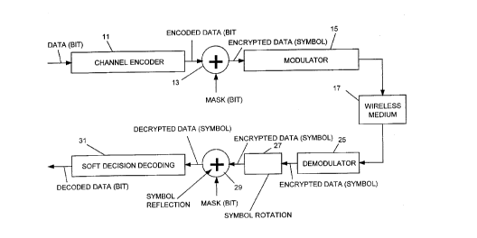
Figure 3 is a block diagram of a system in
accordance with an embodiment of the present invention,
Figure 4 is a phase diagram used to show the
processing of signals in accordance with a general
CA 0224844~ 1998-09-2~
modulation scheme, in accordance with an embodiment of
the present invention, and
Figure 5 is a phase diagram used to show the
processing of signals in accordance with a ~/4 DQPSK
(Differential Quadrature PSK) modulation scheme, in
accordance with an embodiment of the present invention.
DETAILED DESCRIPTION OF EMBODIMENTS OF THE INVENTION
Turning to Figure 3, the apparatus and method
for channel encoding, encrypting and modulating the
encrypted signal is shown. The apparatus is similar to
that of the prior art as shown and described above with
respect to Figure 2. The modulated signal transmitted
via the wireless medium 17 is received by a demodulator
25, which demodulates the slgnal into data symbols.
For use of 2 PSK for modulation, n bits at a
time are used for the symbol reflection, changing the
bit-wise data into symbol format.
In the receiving apparatus, after demodulation
in demodulator 25, the data symbols are applied to a
symbol rotation circuit or process 27, which changes the
phase of each symbol to a degree as will be described
below.
The rotated symbols are applied to a decryption
circuit or process 29 where they are decrypted in soft
symbols format, using a process which uses the same mask
bits used in the encryption structure to control symbol
reflection to respective phases controlled by the groups
of mask bits.
The resulting decrypted soft symbols are applied
to a soft decision decoder 31, which outputs decoded
data in bit format.
More particularly, as an example of operation,
assume that the system consists of a transmitter with
the encryption mask being applied (XORed) to the data
bit stream after convolutional encoding and before ~/4
CA 0224844~ 1998-09-2~
PSK modulation. The mask bit X and Y values, relative to
the most recent symbol, are indicated in the table
below:
MASK Symbol
X YReflection Fx Fy
Axis
l lBoth X & Y
0 lY axis -l ' +l
0 0 No reflection +l ~ +l
.. ... . . . . . . .
l O X axis ~ +l -l
where Fx+ and Fy represent variables in the
equation
Snl ~ = FxRe(sn' ) + iFyIm(sn~ )
where Snll represents the reflected symbol,
Re and Im represent real and imaginary
components, and
Snl = sne i pre, (non-coherent modulation
case) or Sn ' = .~"t' (coherent
modulation case)
where Sn represents the current symbol sample,
~pre represents the phase angle of the
previous symbol sample relative to an x
axis, and
~c est represents the estimated carrier
phase.
The symbol reflection is applied based on the
deciphering mask after rotation relative to a reference.
By doing so, the soft symbols become decrypted in the
symbol domain. This makes soft-decision channel
decoding possible.
CA 0224844~ 1998-09-2~
Symbol reflection in the receiving apparatus for
non-coherent detection is effected using the following
steps. Reference is made to Figure 4, which indicates
the current and previous sample phases on a set of x and
y axes representing sample in the real and imaginary
domains:
(a) Estimate the phase ~3pre of the previous sample.
(b) Rotate the current observed sample by the angle
of ~pre towards the x-axis, i.e. make the previous
sample the reference sample. This can be expressed as
~j~pre
(c) Take n bits each time from the mask for 2 PSK
to form an n-bit mask subset.
(d) Using the predefined reflection rule, the symbol
in the observation domain is reflected about the pre-
defined axes according to the n-bit subset, i.e.
Sn' ' = FxRe(sn' ) + iFyIm(sn' )
using Fx and Fy listed in the table shown above.
This deciphers the data in the symbol domain before
decoding in the soft-decision decoder 31. The result is
the symbol without encryption.
(e) Input the reflected symbols in the soft-decision
decoder 31.
For coherent detection, ~c est should be
substituted for ~pre~ where ~c est is based on carrier
tracking and the previous decision.
For binary PSK (BPSK), it becomes trivial to
perform and the reflection (i.e. a sign change for the
samples when the mask is 1 (a 1 bit mask) and no change
if the mask is 0). For 4PSK, 2 bits are taken from the
mask each time and the table shown above is used.
Figure 5 illustrates a phase diagram for ~/4
DQPSK encryption. When the 2-bit mask subset is 1,0 for
example, the current sample with phase ~cur iS reflected
with respect to the x-axis (i.e. the previous sample or
CA 0224844~ 1998-09-2~
reference). A symbol with a phase near to ~/4 becomes
one near -~/4 instead.
Thus the symbol is reflected about the x-axis
when the x-bit in the 2 bit mask subset is 1; the same
is true for the y-bit.
The method also works for QAM (Quadrature
Amplitude Modulation) and for QPSK modulation schemes of
2-bits per symbol.
For 8 DPSK, if Gray code is used, this method
can achieve optimum results for four out of eight 3-bit
mask combinations.
The invention can be implemented using different
software and hardware configurations, and is not limited
to the embodiments described in detail above. It can be
applied to systems which do not conform to the IS-136
standard, such as wireless systems specified by the
standards other than IS-136 and wire-line modems.
A person understanding this invention may now
think of alternate embodiments and enhancements using
the principles described herein. All such embodiments
and enhancements are considered to be within the spirit
and scope of this invention as defined in the claims
appended hereto.
I (:)