Note: Descriptions are shown in the official language in which they were submitted.
CA 02248502 1998-09-24
CANISTER FOR PREVENTING THE EMANATION OF A
VAPORIZED FUEL GAS
BACKGROUND OF THE INVENTION
Field of the Invention
The present invention relates to a canister mounted on an
automobile for preventing the emanation of a vaporized fuel gas and,
more particularly, to an improvement in the canister comprising a
container having a vaporized fuel gas inlet port and an exit port, an
aggregate of activated carbon in the container for adsorbing the
vaporized fuel gas, and at least a pair of electrodes for heating the
activated carbon through the resistance of the activated carbon, at the
time of desorption of the vaporized fuel gas.
Description of the Prior Art
The present assignee has previously proposed a canister of this
type in Japanese Patent Laid-Open No. 6-280694. The activated
carbon is heated through the resistance of the activated carbon at the
time of desorption of the vaporized fuel gas from the standpoint of
raising the temperature of the vaporized fuel gas adsorbed by the
activated carbon, in order to enhance the kinetic energy and to
promote the desorption of the vaporized fuel gas from the activated
carbon.
The canister is deteriorated by the accumulation of residual gas
that remains adsorbed by the activated carbon but is not desorbed. In
order to enhance the durability of the canister, the desorption must be
effected efficiently and to a sufficient degree.
In the widely known canister using general activated carbon,
however, an electric current flows in small amounts between the two
electrodes due to a high electric resistance and, as a result, there is a
problem that it is difficult to heat the activated carbon up to a required
temperature.
SUMMARY OF THE INVENTION
The object of the present invention is to provide a canister which
is capable of quickly heating the activated carbon by means of the
resistance of the activated carbon, up to a required temperature, by
increasing the amount of current that flows between the two electrodes
1
CA 02248502 2003-11-03
70488-126
by using activated carbon having a low electric resistance,
despite a low voltage at the time of desorption of the
vaporized fuel gas.
In order to accomplish the above-mentioned object
according to the present invention, there is provided a
device for treating vaporized fuel gas, comprising a
container having a vaporized fuel gas inlet port and an exit
port, a charge of activated carbon in the container for
adsorbing vaporized fuel gas, the activated carbon being
highly electrically conductive, and at least one pair of
electrodes for heating the activated carbon through the
resistance thereof to bring about desorption of the
vaporized fuel gas, characterised in that the charge of
activated carbon is in the form of pellets, the pellets
having an electric resistance of not more than 500 52/2.53
cm3, and in that the activated carbon in the pellets has an
average porous diameter ranging from 7 A (70 nm) to 37 A
(370 nm) .
The above-mentioned highly electrically conductive
activated carbon can be quickly heated through the
resistance thereof up to a required temperature with a
voltage of 12 V of a battery mounted on a car. This makes
it possible to desorb the vaporized fuel gas efficiently and
to a sufficient degree. Furthermore, owing to its quick
response, the desorption can be effected depending upon the
operating conditions of an engine. Accordingly, the
vaporized fuel can be realiably supplied to the engine.
However, the desorption of the vaporized fuel gas is
deteriorated as the electric resistance (resistivity) of the
highly electrically conductive activated carbon exceeds
500 S~/2.53 cm3.
2
CA 02248502 2002-10-24
70488-126
The device prefer,~bL.y compz-i.ses a canister which
is capable of adsorbing the vaporized fuel gas to a
sufficient degree and of favorably dersorbing t~hE=_ vaporized
fuel gas that has been adsorbed. 'fh.e vaporized fuel gas
obtained from the gasoline w.h.icrn i~a <x fuc~__., contains a
variety of chemical componeruts. 'The chemical components,
except butane-type compc~nent:.s, r.:an be su=f:icient:ly adsorbed
by general activated carbon hav:Lng a ~°el,.~tively large
average porous diameter . However, t.fve b~.ztane--type
components adhere to thE: gemera:L act:ivatt:ed. carbon but
readily undergo the desorpt_on. Accc:rdingly, the butane-
type components are adsor beef i.n smai 1. am~~uxlts .
as
CA 02248502 1998-09-24
The present inventors have considered the molecular sieve
property of the activated carbon, i.e., have considered that there are
some relationships between the average porous diameter and the
adsorption (adhesion and holding) of the butane-type components,
and have studied the relationships and have arrived at setting the
above-mentioned average porous diameter. That is, once the butane-
type components are adhered to the activated carbon having the
above-mentioned average porous diameter, the activated carbon
exerts the property for holding the butane-type components until the
desorption operation is effected. Therefore, the above-mentioned
activated carbon is capable of adsorbing the vaporized fuel gas to a
sufficient degree.
Moreover, the activated carbon is highly electrically conductive
and permits the vaporized fuel gas to be favorably desorbed upon the
heating of the activated carbon due to the resistance thereof.
A phenomenon occurs when the average porous diameter is
smaller than 7 A, in that the butane-type components are not smoothly
adsorbed and when the average porous diameter exceeds 37 ~, on
the other hand, the butane-type components that are once adhered
are readily desorbed.
BRIEF DESCRIPTION OF THE DRAWINGS
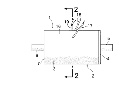
Fig. 1 is a front view of a canister according to an embodiment
of the present invention.
Fig. 2 is a sectional view along the line 2-2 of Fig. 1.
Fig. 3 is a sectional view along the line 3-3 of Fig. 2.
Fig. 4 is a diagram schematically illustrating a testing facility for
adsorbing and desorbing of n-butane.
Fig. 5 is a perspective view of a cell for testing the residual effect
of the electric resistance.
Fig. 6 is a graph showing the relationship between the
adsorption times and the adsorbed amounts of n-butane, and the
relationship between the desorption times and the residual amounts of
n-butane.
Fig. 7 is a graph showing the relationship between the electric
resistance of the activated carbon and the residual amount of n-butane.
3
CA 02248502 1998-09-24
Fig. 8 is a graph showing the relationship between the average
porous diameters of the activated carbon and the maximum adsorbed
amount of n-butane.
Fig. 9 is a graph showing the relationship between the average
porous diameter of the activated carbon and the residual amount of n-
butane.
DETAILED DESCRIPTION OF THE PREFERRED EMBODIMENT
Figs. 1 to 3 illustrate a canister 1 for preventing the emanation of
a vaporized fuel gas. The canister 1 has a container 2 made of a
polyamide 66, and the container 2 includes a cylindrical main body 3
with a bottom wall 7 and a closure plate 4 for closing the open ends of
the cylinder. The closure plate 4 has a hollow cylindrical portion 5
which outwardly protrudes from the central portion thereof, and a
vaporized fuel gas inlet port 6 is formed by the hollow cylindrical
portion 5. The hollow cylindrical portion 5 is connected to a fuel tank
that is not shown. The main body 3 has a hollow cylindrical portion 8
that outwardly protrudes from a central portion of the bottom wall 7,
and a vaporized fuel gas exit port 9 is formed by the hollow cylindrical
portion 8. The hollow cylindrical portion 8 is connected to an air intake
system of an engine that is not shown.
Inside the container 2, there are provided filter layers 10 and 11
made of a glass wool in contact with the closure plate 4 and the
bottom wall 7, respectively. The space between the two filter layers 10
and 11 is filled with an aggregate 13 of pelletized activated carbon 12
for adsorbing the vaporized fuel gas.
At least a pair of, and in this embodiment, a pair of aluminum
plate electrodes 14 and 15 are mounted opposed to each other, on the
inner surfaces of a peripheral wall 16 of the main body 3 and are
buried in the aggregate 13. Lead wires 17 and 18 of the electrodes 14
and 15 extend outwards penetrating through the peripheral wall 16,
and are connected to a DC power source device (not shown). The
electrodes 17 and 18 are used for heating the activated carbon 12
through the resistance thereof. The main body 3 is further provided
with a thermocouple 19 penetrating through the peripheral wall 16, the
thermocouple 19 operates so that the temperature of the activated
carbon 12 will not exceed a predetermined temperature.
4
CA 02248502 1998-09-24
As the activated carbon 12, there is used a highly electrically
conductive activated carbon having an electric resistance of not larger
than 500 52/2.53 cm3. The highly electrically conductive activated
carbon 12 can be quickly heated through the resistance thereof up to a
required temperature with the voltage of a 12 V battery mounted on a
car. This makes it possible to effect the desorption of the vaporized
fuel gas efficiently and to a sufficient degree. Furthermore, owing to its
quick response, the desorption can be effected depending upon the
operation conditions of the engine. Accordingly, the vaporized fuel can
be reliably supplied to the engine.
At least part of the highly electrically conductive activated
carbon in the aggregate 13 has an average porous diameter of not
smaller than 7 ~ and not larger than 37 A. A highly electrically
conductive activated carbon having such an average porous diameter
adsorbs the vaporized fuel gas containing butane-type components to
a sufficient degree.
Concretely described below is an example of using an n-butane
(n-C4H,o) as a vaporized fuel gas.
Fig. 4 illustrates a testing facility 20. In this testing facility 20, a
nitrogen gas source 22 is connected to the inlet port 6 of the canister 1
through a first tubular passage 21. A first cock 23 and a first flow
meter 24 are connected in the first tubular passage 21 extending from
the side of the canister 1. Furthermore, an n-butane source 26 is
connected, via a second tubular passage 25, to the first tubular
passage 21 between the canister 1 and the first cock 23. A second
cock 27 and a second flow meter 28 are connected in the second
tubular passage 25 extending from the side of the canister 1.
The two lead wires 17 and 18 and the thermocouple 19 of the
canister 1 are connected to a DC power source device 29 (regulated
DC power supply, a maximum application voltage of 100 V, a
maximum current of 20 A, manufactured by Kikusui Denshi Co.). The
amount of current flowing between the two electrodes 14 and 15 is
controlled depending upon the temperature data of the thermocouple
19, and the activated carbon 12 is maintained at a constant
temperature.
The canister 1 has sizes as described below.
Container 2: the main body 3 has an inner diameter of 46 mm,
a depth of 80 mm and a thickness of 2 mm.
s
CA 02248502 1998-09-24
Electrodes 14 and 15: 30 mm high, 60 mm wide, 1 mm thick,
and separated apart by 35 mm from each other.
Activated carbon 12: pellets and contained in an amount of 100
cm3, having a diameter of about 2 mm and a thickness of about 2 to 6
mm.
The electric resistance of the activated carbon 12 is measured
by using an electric resistance measuring cell 30 (VOAC 7512,
manufactured by Iwasaki Tsushinki Co.) shown in Fig. 5. The electric
resistance measuring cell 30 comprises an electrically insulating
channel member 31 made of an FRP, and a pair of aluminum plate
electrodes 33 and 34 which are so installed as to close U-shaped
openings 32 formed at both ends thereof. Space 35 between the two
electrodes 33 and 34 is filled with the activated carbon 12. Then, the
electric resistance between the two electrodes 33 and 34 is measured
and the measured value is regarded to be the electric resistance of the
activated carbon 12. Here, the space 35 has a volume measuring 2.5
cm high, 2.5 cm wide and 2.5 cm deep, i.e., has a volume of 2.53 cm3
(15.625 cm3). Therefore, the electric resistance of the activated
carbon 12 is expressed as ohms per 2.53 cm3.
The adsorption and desorption of n-butane were tested
according to a procedure described below.
(a) First, the weight of the canister 1 that has not been used
is measured.
(b) Referring to Fig. 4, the first tubular passage 21 is
connected to the canister 1. In this case, the canister 1 is not
connected to the DC power source device 29.
(c) The first cock 23 is opened, a nitrogen gas having a purity
of 99.999% is supplied from the nitrogen gas source 22 into the
canister 1 at a flow rate of one liter a minute for 5 minutes through the
inlet port 6 being directed to the exit port 9 to substitute the gas in the
canister 1 with the nitrogen gas.
(d) While the nitrogen gas is being supplied under the above-
mentioned conditions, the second cock 27 is opened, and the n-butane
having a purity of 99% is supplied from the n-butane source 26 at a
flow rate of one liter a minute. That is, a mixed gas of nitrogen gas
and n-butane is supplied into the canister 1 through the inlet port 6
being directed to the exit port 9, and the amount of n-butane adsorbed
by the activated carbon 12 is measured with the passage of time. To
6
CA 02248502 1998-09-24
measure the amount of adsorption, the first tubular passage 21 is
disconnected from the canister 1 after the passage of a predetermined
period of time, and the weight of the canister 1 is measured. From the
measured weight is subtracted from the weight of the canister 1 before
being tested, and the difference is regarded to be an adsorbed amount
of n-butane.
When the mixed gas is allowed to flow for about 10 minutes, the
adsorption of n-butane by the activated carbon 12 reaches the
saturated state. Therefore, the supply of the mixed gas is
discontinued and, then, the adsorbed amount of n-butane is
determined, i.e., a maximum amount of adsorption is found.
(e) The first tubular passage 21 and the DC power source
device 29 are connected to the canister 1.
(f) Presuming a battery mounted on a car with a voltage of
12 V is applied across the two electrodes 14 and 15 from the DC
power source device 29 in order to heat the activated carbon 12
through the resistance thereof. Here, the amount of current is
adjusted depending upon the temperature data from the thermocouple
19, and the temperature of the activated carbon 12 is controlled not to
exceed 120°C.
The first cock 23 is opened, the nitrogen gas having a purity of
99.999% is supplied from the nitrogen gas source 22 into the canister
1 at a flow rate of two liters a minute for 20 minutes through the inlet
port 6 being directed to the exit port 9, to effect the desorption of n-
butane while measuring the residual amount of n-butane with the
passage of time. The residual amount is measured by measuring the
weight of the canister 1 in the same manner as described above. After
the nitrogen gas is allowed to flow for 20 minutes, the weight of the
canister 1 before being tested is subtracted from the weight of the
canister 1 after the testing, in order to find the finally residual amount
of n-butane.
Table 1 shows characteristics of the activated carbons used in
the tests 1 to fi.
CA 02248502 1998-09-24
Table 1
Test No. Activated carbon
Material Electric ResistanceAverage porous
52/2.53 cm3 diameter ~
1 Coconut shell 296 17
2 Coal 108 27
3 Phenolic resin21 37
4 Coconut shell 497 7
Coconut shell 350 4
6 Wood 627 45
Table 2 shows maximum temperatures of the activated carbon
being tested, maximum amounts of adsorption of n-butane, effective
amounts of adsorption and finally residual amounts in test Nos. 1 to 6.
Here, the effective amount of adsorption stands for a value obtained
by subtracting the finally residual amount from the maximum amount
of adsorption, i.e., stands for the amount of desorption of n-butane.
Table 2
Test No. Max. temp, of n-Butane
activated Carbon
( C) being tested
Max. amountEffective Residual
of adsorptionamount of amount
(g) adsorption (g)
1 83 9.4 9.3 0.1
2 95 9.1 9.0 0.1
3 120 8.7 8.5 0.2
4 70 7.7 7.5 0.2
5 77 5.1 4.9 0.2
6 60 6.3 5.4 0.9
Fig. 6 illustrates the relationship between the adsorption times
and the maximum adsorbed amount of n-butane and relationship
between the desorption times and the residual amount related to test
Nos. 1 to 6. In Fig. 6, numerals (1 ) to (6) correspond to test Nos. 1 to
s
CA 02248502 1998-09-24
6, respectively. This relationship is analogous in the subsequent
drawings, also. It will be understood from Fig. 6 that the adsorption of
n-butane reaches the saturated state in 10 minutes after the start of
the testing and, thereafter, the desorption of n-butane takes place.
The average gas desorption rates during two minutes from the
start of desorption were as set forth below in, for example, test Nos. 3,
4 and 6.
Test No. 3 3.75 g/min.
Test No. 4 2.50 g/min.
Test No. 6 1.15 g/min.
Fig. 7 is a graph showing the relationship between the electric
resistance of the activated carbon and the residual amounts of n-
butane in the test Nos. 1 to 6 based upon Tables 1 and 2. As will be
obvious from Table 2 and Fig. 7, the highly electrically conductive
activated carbon having an electric resistance of not larger than 500
52/2.53 cm3 can be heated through the resistance of the activated
carbon at a temperature of not lower than 70° C with a voltage which
is as low as 12 V as is done in test Nos. 1 to 5 and, thus, the n-butane
is desorbed efficiently and to a sufficient degree.
Fig. 8 is a graph showing the relationship between the average
porous diameters of the activated carbon and the maximum adsorbed
amount of n-butane in the test Nos. 1 to 6 based upon Tables 1 and 2.
As will be obvious from Fig. 8, when the highly electrically conductive
activated carbon having an average porous diameter of not smaller
than 7 ~ and not larger than 37 A is used as in test Nos. 1 to 4, the
maximum adsorbed amount of n-butane can be increased. In this
case, a corresponding effect can be obtained even when the
aggregate of activated carbon partly contains the highly conducting
activated carbon having the above-mentioned average porous
diameter.
Fig. 9 is a graph showing the relationship between the average
porous diameter of the activated carbon and the residual amount of n-
butane in the test Nos. 1 to 6 based upon Tables 1 and 2. As will be
obvious from Fig. 9, when the highly electrically conductive activated
carbon, having an average porous diameter of not smaller than 7 ~
and not larger than 37 ~ is used as in test Nos. 1 to 4, the residual
amount of n-butane also tends to decrease.
9
CA 02248502 1998-09-24
According to the present invention, there is provided a canister
as described above, which is capable of desorbing the vaporized fuel
gas efficiently and to a sufficient degree by quickly heating the
activated carbon through the resistance of the activated carbon up to a
required temperature at the time of desorption of the vaporized fuel
gas.
Further, there is provided a canister capable of adsorbing the
vaporized fuel gas to a sufficient degree in addition to obtaining the
above-mentioned effect.
The present invention may be embodied in other specific forms without
departing from the spirit or essential characteristics thereof. The
presently disclosed embodiments are therefore to be considered in all
respects as illustrative and not restrictive, the scope of the invention
being indicated by the appended claims, rather than the foregoing
description, and all changes which come within the meaning and range
of equivalency of the claims are, therefore, to be embraced therein.