Note: Descriptions are shown in the official language in which they were submitted.
CA 02248709 1998-09-11
WO 97/34148 PCT/IB97/00255
IMMUNOASSAY DEVICE
FIELD OF THE INVENTION
This invention relates to devices and methods useful for diagnostic assays to
determine the presence of analytes characteristic of a diseased condition such as
S cardiac malfunction or microbial infection. More particularly, it is useful for
identifying analytes in whole blood, although it is not so limited.
BACKGROUND OF THE INVENTION
A number of immunoassay procedures have recently been developed which utilize
reactions taking place on a porous or cellular membrane, the reactions being
- 10 detectable either visually or with an instrument such as a reflectometer. While not
so limited, these procedures generally involve antigen/antibody reactions in which
one member of the reactive pair is labelled with a detectable label. Typically, the
label is an enzyme label or a sol label such as gold. The art is well aware of many
useful labels and their method of operation. Hence, there is no need for furtherdiscussions of labels herein.
Typical immunochromatographic devices of this nature are described in several
United States and foreign patents. For example, United States Patent 4,861,711
describes a device in which an analyte detected by antigen/antibody reactions which
take place in a series of coplanar membranes in edge to edge contact.
United States Patents 4,477,575 and 4,816,224 describe laminar devices including a
glass fiber layer for conducting similar reactions.
Other l~min~ted devices are described in United States Patents:
4,774,192 5,079,142
4,753,776 5,096,809
4,933,092 5,110,724
4,987,065 5,144,890
~:0NF~RM~10N C0P~
CA 02248709 1998-09-11
wO 97/34148 PCT/Is97/00255
5,075,078 5,290~678
5,135,716 5,591,645
U.S. Patent No. 5,135,716 utilizes an agghltin~ting agent to assist in the separation
of red blood cells. All of the patents describe l~rnin~tçd devices.
5 So far as applicants are aware, no non-l~min~ted immunochromatographic device
operable with whole blood has been previously known or described.
Devices such as those described in the above identified patents are often difficult to
manufacture because they are multi-layer and require several layers of porous and
filtration strips to insure accurate results. For detection of analytes in whole blood,
- 10 it is necessary to remove red blood cells so that they will not interfere with
visll~li7.ing the colored product which is usually the consequence of the
immunoassay reactions. Glass fiber fleeces have been used for filtration but this
simply adds another layer to the device. The difficulties arise because of the
problems of accurately placing several layers of thin flexible strips in proper
15 registry one on the other while at the same time retaining the sample placement
zones, reaction zones and other areas of the strips in proper relationship with each
other. The problems are further complicated by the difficulties of placing the
completed device in or on a proper platform which is often a hollow casing with
separable upper and lower members including fixed pillars and slots to prevent the
20 device from moving and to retain defined areas of the device in proper position
relative to viewing windows and other openings in the casing.
Immunoassay instruments such as the foregoing when employed to detect analytes
in whole blood utilize labels on the antibodies to the analytes which give rise to a
detectable product. In the usual case a labelled detector antibody reacts with one
25 epitope on the analyte and a capture antibody reacts with another epitope on the
analyte. Typically, the product is visibly detectable because it is colored. In some
constructions, the color is apparent to the naked eye. In more sophisticated devices,
CA 02248709 1998-09-11
- wo 97/34148 PcT/Isg7/002ss
the concentration of the analyte may be determined by measuring the intensity ofthe produced color with a suitable instrument. In both instances, the presence of
red blood cells in the color development area interferes with proper visualization of
the color because of the intense hue of the cells.
5 Much effort has been expended to prevent such interference. As a result, all devices
proposed for analysis of whole blood include some type of filter to remove the red
blood cells to produce serum or plasma which does not mar the visibility of the
color which is produced. A glass fiber fleece issued in the device of United States
Patent 4,477,575 to filter the red blood cells. Other patents describe the use of
10 paper or plastic filters.
BRIEF SUMMARY OF THE INVENTION
This invention provides a device in which all of the reactions necessary to
determine the presence of an analyte in whole blood without interference by red
blood cells take place on one or at most two membrane devices assembled by easy
15 manufacturing techniques. The device may be contained in a very simple casing.
Although the invention is not so limited~ for convenience, it will be described as
utilized for the detection of cardiac analytes in whole blood. It may additionally be
employed for detecting and/or measuring a wide variety of analytes in blood, such
as: drugs, including therapeutic drugs and drugs of abuse; hormones, vitamins,
20 proteins, including antibodies of all classes, peptides; steroids; bacteria; fungi;
viruses; parasites: components or products of bacteria, fungi, viruses, or parasites:
allergens of all types: products or components or normal or m~lign~nt cells; etc. As
particular examples~ there may be mentioned digoxin, hCG; insulin; theophylline;luteinizing hormone: thyroid stimulating hormone; org~nism.~ causing or associated
25 with various disease states, such as streptococcus pyrogens (group A), HerpesSimples I and II, cytomegalovirus, Chlamydia, rubella antibody, etc.
CA 02248709 1998-09-ll
W O 97t34148 PCT~B97/00255
An important feature of this invention is the geometry of the device which when
utilized for whole blood analysis is designed to provide a stream from which
substantially all of the red blood cells have been separated. As a result of thegeometric design of the device, a fixed volume of plasma is in contact with a
5 preselected area of the device for a longer period of time, thus providing sufficient
contact time for binding reactions to take place. Said fixed volume is determined
by the volumetric capacity of the membrane.
BRIEF DESCRIPTION OF THE DRAWINGS
This invention will be best understood when considered in conjunction with the
10 following description which, together with the drawings, form part of this
specification wherein:
Fig. 1 is a plan view of a unilayer device of the invention.
Fig. 2 is a plan view of a device of the invention in which a top long membrane is
unfolded and rotated 180~ with respect to another shorter membrane over which it15 is superimposed in fluid contact.
Fig. 3 is a plan view of a product of the invention showing four devices of the
invention in the same unitary structure.
Fig. 4 is an exploded view of an alternate product of the invention showing a
bilayer device of the invention on a platform with upper and lower members.
20 Fig. 5a shows a section through a device housing corresponding to the current Figure 4.
Fig. 5b shows a plan view of the upper membrane for use in Figure. 5a.
CA 02248709 1998-09-11
wo 97/34148 PCT/Is97/00255
Fig. 5c shows a plan view of the lower membrane for use in Figure 5a.
~ig. 6a shows a section through device housing avoiding the use of a hole in theupper membrane shown in Figure 4.
Fig. 6b shows a plan view of the upper membrane for use in Figure 6a.
5 Fig. 6c shows a plan view of the lower membrane for use in Figure 6a.
Fig. 7 shows the single membrane device used in Example 2. The parts are
identified by name for easy understanding.
- Fig. 8 shows the device used in Example 3. The parts are similarly identified.
Fig. 9 shows the device used in Example ~ similarly labeled.
DETAILED DESCRIPTION OF THE INVENTION
In this description of the invention~ the device is the membrane structure employed
to chromatographically retard the flow of red blood cells in blood applied to anapplication zone thereof thereby to transform the whole blood into a stream with a
plasma front followed by a front of the slower moving red blood cells. The device
15 is particularly adapted and well suited for the reception and diagnostic processing
of small quantities of fluid sample, such as droplets of whole blood received from a
finger prick procedure. The membrane structure also serves as a substrate for the
diagnostic reactions. The casing is the carrier, holder or platform for the device. A
product of the invention is the combination of a device and a casing.
20 A major contributing factor to the invention described and claimed herein is the
discovery that cellular membranes constructed, preferably, of nitrocellulose will
preferentially retard or inhibit the flow of red blood cells moving along the
CA 02248709 1998-09-11
W 097/34148 PCT~B97100255
membrane, thereby forming a stream presenting a red blood cell front and
downstream thereof a plasma front. More specifically, the red blood cells are not
filtered from the whole blood but are separated chromatographically from the
plasma which, in the selected membrane substrate~ flows faster than the red blood
5 cells.
Another feature of the invention is that the plasma segment or section of the
stream, which is substantially free of red blood cells, is manipulated so that it flows
slowly through the area where certain of the diagnostically useful reactions take
place. This feature will be explained in more detail hereinafter.
10 Devices of this invention are designed with a sample application zone to which the
- blood sample is applied, and downstream of the sample application zone, a flow
zone, such as, for example an elongated reaction zone including a detector zone
upstream of a capture zone. In this respect, a device of the invention is not unlike
previously known devices such as those described in the patents identified above.
15 The critical features on all such devices is that an analyte, for example myoglobin
or myosin light chain in the blood, reacts with a colored, mobile labelled antibody
to the analyte in the reaction zone to form an antigen/antibody complex. This
complex is soluble or suspended in the carrier liquid and moves down the
membrane to react with a capture antibody to form a visible
20 antibody/antigen/antibody reaction product, wherein the antigen is the analyte. All
such devices when employed with whole blood to achieve diagnosis by the
production of color product employ some type of filter to stop the flow of red
blood cells and separate them from the areas where the useful diagnostic reactions
take place to avoid interference with color formation and interpretation. Typically,
25 the filter is a glass fiber, plastic, or cellulose paper filter, which removes the red
blood cells as the blood moves longitudinally from the point of application towards
the reaction area.
CA 02248709 1998-09-11
Wo 97/34148 PcT/Isg7/002s5
In contrast to such previously known diagnostic constructions, the device of this
invention achieves a chromatographic separation where the red blood cells continue
to flow but at a slower rate than the plasma or serum. Hence the red blood cellsare separated from the plasma chromatographically rather than by filtration.
5 It has been surprisingly discovered that whole blood, as it moves along a
membrane such as a nitrocellulose membrane, is separated chromatographically into
a relatively fast moving plasma strearn and a relatively slow moving red blood cell
stream. As a result, the red blood cells become separated from the plasma. In a
device of the invention. the initial immunological reactions may take place even10 before the plasma front of the stream substantially free of red blood cells has been
formed. The reaction continues in the separated plasma to provide diagnosticallyuseful information.
During an ischemic event such as stable or unstable angina or myocardial
infarction, a variety of different proteins characteristic of the event are released by
l S cardiac tissue~ These proteins which are referred to as analytes may be useddiagnostically as described in U.S. Patents No. 5,290,678 and No. 5,604,105, thedisclosures of which are incorporated herein by reference. Typical examples of
analytes are myoglobin. cre~tinin~ kinase-MB (CK-MB), myosin light chain,
troponin I, and troponin T. As described in these patents, the presence of these20 analytes in whole blood is determined by antigen/antibody reactions which take
place in l~min~tcd structure in which the analyte first contacts labelled detector
antibody which reacts with a first epitope on the analyte to form a labelled
antibody/analyte complex. The complex then contacts a capture antibody which
reacts with another epitope on the analyte to form a visible labelled
25 antibody/analyte/detector antibody reaction product. As described in the patents,
detection of the presence of at least three analytes in more than normal arnounts
perrnits the physician to accurately characterize the cardiac event as stable orunstable angina or as a myocardial infarction. There are many other cardiac
analytes which may be similarly employed. Devices with only one or two analytes
CA 02248709 1998-09-11
W O 97/34148 PCT~B97100255
are also available, but generally are not capable of giving as much information as
devices adapted to three or more analytes.
A clear underst~nding of this invention will be facilitated by a description of some
specific embodiments, The description will be followed by a discussion of some of
S the general considerations involved in designing products of the invention.
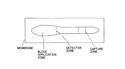
Figure 1 shows a typical device of the invention comprised of a membrane 10
configured as shown.
The membrane includes a sample application zone 12 to which one or more drops
of whole blood may be applied. As noted earlier, it is a particular advantage of the
10 invention that whole blood may be directly analyzed and that only small amounts
of blood, e.g., about 8 to 20~11 or even less are required. This amount of bloodmay be obtained and applied directly from a finger prick or from a dropper or
pipette after withdrawal from a patient.
The blood moves downstrearn of the application zone 12 to a reaction zone which
15 includes a detector zone 14 cont~ining a labelled detector antibody reactive with an
epitope on the analyte to produce a labelled antibody/analyte complex. This
reaction is well known and need not to be described in detail.
Any of a variety of labels available to the skilled artisan may be utilized. Metal and
enzyme labels are preferred. Metal labels are especially preferred due to their
20 remarkable sensitivity. Amongst the metals, gold is most preferred principally
because it is so widely employed for this type of reaction and its characteristics are
so well understood. Additionally, a gold signal can be enhanced to become readily
visible by the use of a soluble silver salt and a reducing agent in accordance with
known procedures. The gold label acts as a catalyst to reduce the silver salt to25 metallic silven which deposits as a visible product. A typical reactive pair is silver
lactate, which serves as the source of reducible silver ions, and hydroquinine as a
CA 02248709 1998-09-11
Wo 97/34148 PCTns97/00255
reducing agent. The metallic silver forms a readily discernible black deposit around
each particle of gold.
There may be a preincubation zone starting in the application zone and continuing
to the detector zone although it is not a necessary feature of the invention. The
S preincubation zone is employed to remove products present in the blood which may
interfere with the desired reactions or make them difficult to detect. A typicalinterferant is the isoform of creatine kinase, CK-MM. Antibodies to the isoform
CK-MB may cross react with CK-MM and give false readings. This can be avoided
by providing sufficient immobilized antibody to CK-MM in a preincubation zone
10 so that all of the CK-MM is removed before the moving sample reaches the
detection zone.
-
The device of Figure 1 may utilize one or a plurality labelled detector antibodies.When several labelled detectors are employed care must be exercised to avoid
interfering reactions. It is often best that the antibodies be arranged in one or more
15 detection zones to react with their specific analytes.
The labelled detector antibody is mobile, i.e., it is movably bound to the membrane
10 in the detector zone 14 so that the labelled antibody/analyte complex, once
formed, is free to move downstream. Of course, antibodies employed in this
reaction or in reactions subsequently to be described may be either monoclonal or
20 polyclonal. A large number of such antibodies are well known and readily
available or can be prepared by standard procedures.
As the blood moves downstream away from the application zone 12 the red blood
cells move more slowly than the plasma, and form a front 16. A proportion of theplasma component of the original blood sample continues downstream as a plasma
25 segment the front of which is indicated in Fig. 1 at 1~. Ultimately, and as
indicated above, substantially all of the red blood cells are confined to an area
encompassing the application zone 12 and the red blood cell front 16. If a labelled
CA 02248709 1998-09-11
- wo 97/34148 PcT/Isg7/00255
antibody/analyte complex has formed it will be dissolved in the plasma and carried
towards the capture zone 20. In the capture zone, the complex will contact a
capture antibody, which will react with the complex to form a detectable labelled
antibody/analyte/antibody reaction product.
S It will be noted that the first reaction of the labelled antibody and analyte may talce
place in the whole blood stream in the presence of the red blood cells. For proper
analysis of the analytes in the blood sample, it is not necessary to know at this
point that a detector antibody has reacted with an analyte. The red blood cells are
not interferants. If desired, however, the complex may be formed downstream of
10 the red blood cell front 16 by appropriate placement of the labelled antibody, but
this may unnecessarily increase the length of the device.
If the label is a sol such as gold, a visible line will form, which as suggested above
may be the gold product or may be reduced silver. If the label is an enzyme suchas horseradish peroxidase, reaction may be detected by the addition of hydrogen
15 peroxide and a dye such as ortho phenylenediamine in accordance with standard procedures.
The device of Fig. I includes a control zone 22, which may contain a product that
reacts with any substance normally present in blood and in plasma to produce a
visible product. The use of a control reaction is optional, but is preferred so that
20 the operator will know that sufficient blood has been applied in the application
zone 12 and that the diagnostic reactions have had the opportunity to take place.
Those skilled in the art will recognize that the reactions described will each have
characteristic reaction kinetics and eacll will require a period of time for thereaction to be completed. To insure that there will be sufficient time for
25 completion of the reaction with the capture antibody and production of sufficient
readily visible product, the device of the invention is configured so that the flow
CA 02248709 1998-09-11
W O 97/34148 PCT~B97/00255
11
rate of the plasma strearn is retarded and there is more time for reaction of the
labelled antibody/analyte complex with the capture antibody.
In general, modulation or control of the flow of the fluid sample and its
components may be achieved by different means. For example, the membrane may
5 be configured so that fluid flow (i.e., flow of the plasma) may be elongated to
extend to the end of the membrane. Another way in which flow may be controlled
is by constricting the channels, either in size or in number, through which suchflow may take place. A third way to control flow is to apply a predetermined
volume of sample to the membrane, so that the amount of such sarnple corresponds10 to the volume that will fill only the channels available in the membrane for such
fluid flow.
Accordingly, the device may include a flow modulation or control means associated
with the membrane or strips, which may comprise, for example, one or more
restrictions in the width of the membrane, or the placement of one or more baffles
15 or like flow barriers, to inhibit plasma flow. Such baffles may be formed by
compressions in the membrane which would elimin~te porosity and, consequently,
would inhibit or prevent flow therethrough.
Flow modulation or restriction may also be accomplished by elongating the plasmastream so that the distance a fixed volume of plasma must flow before it reaches a
20 capture antibody increases. The ultimate result is that the total volume of plasma
remains in the capture zone 20 for a longer period of time. The volumetric
capacity of the strip between capture zone 20 and end of the strip lOa determines
the volume of plasma that flows through the capture region 20. That is flow stops
when the strip is totally saturated. Furthermore, this also prevents further flow of
25 red cells and prevents them ~rom obscuring the capture region. Naturally,
variations in device design, construction, shape and size are contemplated within
the scope of the present invention.
CA 02248709 l998-09-ll
W O 97/34148 PCT~B97/00255
Another function of the elongation is to provide a greater separation between the
red blood cell front and the plasma front 18 for a minimum plasma volume. This
is important to minimi7~ the possibility of the red blood cells migrating into the
capture zone 20 and confusing the results. There are several means of
5 accomplishing the elongation of the route the plasma segment must follow. One
such means is shown in Fig. I which shows an indentation of the sides of the
membrane to form a neck 24. The neck may be formed by cutting the edges of the
membrane. However, such cutting should be accomplished, e.g., by a laser device,as conventional means may compress the capillary space, i.e., pores. along the
10 edges of the channels in the membrane, and may thereby interfere with fluid flow.
It may also be formed by compressing the membrane to form a compressed section
of the desired shape through which the plasma is unable to flow. The same resultmay also be achieved by impregnating the membrane with wax or another inert
substance to also form the desired configuration through which the plasma will not
1 5 flow.
Still other alternatives include compressing a series of round, square or elongated
designs across the membrane in the area shown as a neck 24 in Fig. l. If this
alternative is chosen, there is no indentation of the membrane, but the compressed
segments impede the flow of the plasma in a manner analogous to that in which
20 rocks impede the flow of water in a river.
Fig. 2 illustrates an embodiment of the invention in which the application zone 12
and detection zone 14 are in a lower membrane layer 26 under the upstream end ofa upper membrane layer 29. The advantage of this design is that the length of the
device and the flow time through the device are both decreased. This is
25 accomplished while retaining the essential flow of the sample through the device
and without loss of the chromatographic effect. Hence, a larger volume of blood
can be analyzed in a shorter period of time. An alternate structure would be a
locally increasing width of the membrane. However, this is not preferred since it
CA 02248709 1998-09-11
WO 97/34148 PCT/IB97/00255
alters the flow characteristics by forming stagnation regions in which plasma may
collect but not flow.
In the device of Fig. 2, the application zone 12 is the section of the lower layer 26
under the through hole 27 through which the blood is applied before flowing
5 downstream in the lower layer 26 through detection zone 14 and into the upper
layer 29. The area around the through hole 27 in the application zone 12 of the
upper layer 29 is a blocked area 28 formed for example by compression or with
wax. The purpose of the blocking is to prevent the blood from flowing
downstream in the upper layer 29 and forming a channel for the blood to flow into
10 the detection zone 14 of the lower layer 26.
- The whole blood flows through the detection zone 14 where the analyte, if present,
contacts and reacts with a labelled detection antibody and then into the upper
member 29. The operation of the device of Fig. 2 is thereafter the same as the
device of Fig. 1. There is a red blood cell front 16, a plasma stream with front 18,
15 a control zone 22 and a neck 24.
It will be noted that in the device of Fig. 27 the downstream end 30 of lower
member 26 overlaps the blocked area 28 of upper member 29 so as to form a flow
path for the blood. Blocked area 28 may consist of a wax or other aqueous liquidimpervious coating to control liquid flow. The ultimate effect of the arrangement
shown in Fig. 2 is to form a flow channel which forces the blood to flow from the
application zone 12 through the detection zone 14 and towards the capture zone 20.
The flow is still essentially along the membranes, thus maintaining the
chromatographic effect.
The position of the layers shown in Fig. 2 may be inverted, in which case through
25 hole 27 would not be required. The direction of flow is still substantially along the
membranes.
CA 02248709 1998-09-11
W O 97134148 PCT~B97/00255
14
The effect of the overlapping membrane construction is to maximize the amount ofblood that the device can utilize without making the test duration excessive while
still retaining essentially longitudinal flow.
Fig. 3 illustrates an embodiment of the invention in which four devices are on the
5 same substrate 60. All of the devices share application zone 12. Blood added at
application zone 12 flows through each device and reacts in the same manner as
previously described.
The multiple device embodiment may be printed on one sheet of membrane
material by forming the lines defining each device by compression or heat or by
10 printing the lines on the membrane sheet with wax or another material which will
form the proper flow channels in each device. Alternatively, the multiple devicecan be separately formed by cutting it from a membrane sheet and adhering it to an
inert substrate such as a plastic sheet with no capillary attraction for the flowing
blood or plasma. In fact, nitrocellulose membranes with polyester backings are
15 commercially available and presently preferred for producing the various devices of
this invention.
Other configurations of the multiple device embodiment will be apparent to thoseskilled in the art. For example. the devices can be set in a side by side
configuration as shown in Fig. 4.
20 Fig. 4 illustrates an embodiment of the invention in which two adjacent devices are
supported in a casing 30 having a cover member7 36, and a support member, 34.
As shown, the product of the invention supports two devices, each with a detection
zone 14. In Fig. 4, those numerals are identical to numerals in the other figures
have the same meaning.
25 The figure is an exploded view showing two joined devices each designated as 10
backed with a polyester sheet 32 in the casing comprising a support member 34
CA 02248709 1998-09-11
W 097/34148 PCTAB97/00255
and a cover member 36 for connection to the support member 34 to enclose the
devices 10.
The cover member 36 includes a through hole 38 in registry with the application
zone 12 for applying whole blood. It also includes view windows 40 in registry
5 with the capture zones 20 present on each of the devices lO and, if present, control
zones 22, to permit the operator to view the results.
The cover member 36 may optionally contain a sufficient sample indicator hole 42,
which will allow the operator to determine if sufficient blood has been added tocomplete the test. It may also contain a test end signal view hole 44, which will
10 advise the operator that sufficient time has passed so that the results can be read
- without danger of false negatives due to early reading. The same safety
requirement can be t'ulfilled with a stop watch or other timing device.
If a test end signal is desired, a spot of dye can be placed at the end of a device if
only one is used~ or at the end of one of the devices if multiple devices are
15 employed. In either event, the dye will be upstream of the view hole 40. It will
be dissolved in the flowing plasma and carried to the view hole 44 to signal theoperator that it is time to read the test.
More specifically, the region 46 of device lO (Fig. 4) shows the configuration of a
timing device which extends under the viewing window 44. A dye will be placed
20 between the control zone 22 and the section of the extension 46 which is under the
window 44. The appearance of the dye under the window 44 will signal the
operator that it is time to read the results.
Members 48 support the device in the casing 30.
Fig. 5A shows a simplified cover member 51 and simplified lower support member
25 52. Aperture 53 provides access for blood to be applied through hole 27 in the
CA 02248709 1998-09-11
Wo 97/34148 PCT/IB97/00255
16
upper membrane 29 and hence onto lower membrane 26. The dark region of the
two membranes corresponds to the polyester backing, and the dotted region to thenitrocellulose. ~he hatched region 28 of upper membrane is a wax barrier to
prevent blood wicking directly into upper membrane. The hatched regions 54a and
5 54b in lower membrane 12 merely prevent stagnation loss of blood in the corners.
Wax line 55 serves to restrict the rate of flow of blood into the lower and upper
membranes. Clearance region 56? surrounding aperture 53, prevents blood wicking
along the capillary channels that may otherwise be formed between upper housing
and the polyester surface of upper membrane. The width of capture region 57 is
l0 enlarged relative to throat region to provide improved visibility of the analytical
result.
- Fig. 6A is similar to the above but avoids the need to provide a hole in the upper
membrane. The upper membrane l0 is made shorter so that aperture 63 connects
blood application directly to the application zone 12 of the lower membrane 26.
15 The other features are as described above and the numerals have the same meaning.
The operability of the test devices of the invention depends ultimately on separating
the red blood cells from whole blood so as to permit substantially clear plasma
cont~inin~; the labelled antibody/analyte complex to reach the capture zone 20 so
that a color change is detectable without interference from the strong color of the
20 red blood cells. It was not, heretofore, appreciated that such a result could be
realized without the use of separate vertical membranes to remove the red blood
cells by filtration, in which the flow is through the thickness of the membrane.
A few simple observations will be sufficient to determine where the red blood cell
front and clear plasma will appear on a cellular membrane of defined dimensions
25 and pore size. Once that is known, the skilled artisan knowing the analyte which is
being tested, the affinity for the analyte of the antibodies employed, and the
kinetics of the reactions, will know where to place the antibody and the captureantibody as well as an ~plo~1iate length of the device. Even if these factors are
CA 02248709 1998-09-11
- WO 97/34148 PCT/IB97/00255
not known, the optimum pOSitiOIIS for the antibodies and the length of the plasma
stream to provide the optimum signal can be readily determined empirically. All
of this is well within the skill of the art.
The skilled artisan will recognize that any membrane that chromatographically
5 separates red blood cells and plasma from whole blood may be employed in this
invention. However~ nitrocellulose is preferred because it is readily available at
reasonable cost. Nitrocellulose has been employed in chromatography and related
fields for so many years that scientists and technicians are f~mili~r with its
properties.
10 Commercially available nitrocellulose can be readily formed into thin strips of any
selected length and width.
The nitrocellulose membranes of the invention may be characterized as sponge-like
with a plurality of interconnected micropores of various sizes and dimensions
giving rise to capillary forces within the membrane. This permits the biological15 fluid under investigation to move along the strip away from a sample application
zone.
For the separation of plasma from red blood cells in the practice of this inventiom
the membrane material, geometry and dimensions are so selected that the desired
reactions take place in preselected areas. These areas are selected-on the basis of
20 the relative speeds of the fronts of the red blood cell stream and the plasma stream.
The kinetics of the desired reactions, the affinity of the antibodies for their
respective epitopes. the size of the reacting particles and other factors are known or
readily determined by conventional testing procedures.
While a variety of nitrocellulose membranes are available in various cell sizes, the
25 presently preferred membranes are those which, if used as a filter, that is filtering
particles from a liquid stream flowing vertically to the perpendicular surface of the
CA 02248709 1998-09-11
W O 97/34148 PCT~B97/00255
18
membrane, will prevent the passage of particles larger than from 3 to 12 ~m. In
the practice of the invention, membranes with a pore size from about S to 12 ~m,preferably 3 to g ,um, are preferred. Some variation is possible. However? as the
pore size decreases, the mobility of a fluid within the membrane decreases, thereby
5 increasing the time required for diagnosis. If the pores are too large, the time of
passage reduces with the result that the reactants are not in contact with each other
for a sufficient period for the diagnostic reactions to occur, or to occur to such a
limited extent that they do not provide the desired information.
Nitrocellulose membranes with supporting polyester or other films are
10 commercially available. These are preferred for use in this invention since
unsupported membranes tend to be quite fragile and susceptible to fracture.
Moreover, the films are impervious to the flowing fluids so that substantially
longitudinal flow channels can be formed by proper placement of the membranes
within a housing. One such membrane is available to a variety of pore sizes from15 Gerberrnembrane of Gerber~h~ncen, Germany.
Procedures for the preparation of labelled antibodies for use in this invention are
well known to the skilled artisan and need not be described in detail. The
presently preferred labels are metal labels, particularly gold labels, the visibility and
sensitivity of which can be enhanced using silver in accordance with known
20 techniques. The preferred particle size for gold labelled antibodies used in the
invention is from about 35 to 65 nrn, although appreciable variation can be
tolerated depending on well understood factors such as the concentration of the
analyte and the affinity of the reactants.
The antibodies employed in this invention are prepared by standard techniques.
25 See for example, Falfre, Howe, Milstein et al., Nature Vol. 266, 7, 550-552, April
1977. The disclosure of this seminal article on the preparation of monoclonal
antibodies is incorporated herein by reference.
CA 02248709 1998-09-11
- wo 97/34148 PcT/Is97/0025s
19
Procedures for fixing antibodies to substrates such as nitrocellulose are known and
usable in producing the devices of this invention. Nitrocellulose is an avid binder
for proteins. Hence~ the immobile capture antibody need only be applied into thecapture zone in a predetermined area. The labelled detector antibody may be
5 movably affixed to the membrane by first saturating the detector zone 14 with
another protein such as bovine serum albumin.
The optimum procedure for practicing this invention, which is applicable when
antibodies with proper affinity for the analyte are available; when these antibodies
can be effectively labelled with, for example a metal or enzyme label; when the
10 reaction kinetics are favorable; and when the various reaction products move
through the membrane at practical rates~ is accomplished in four simple steps.
- These are:
I ) Add a small amount of blood to the application zone,
2) Permit the blood to move into the detection zone where the analyte, if present,
15 complexes with a mobile labelled antibody to the analyte to form a labelled
antibody/analyte complex which will flow with the blood,
3) Allow the blood contS~ining the complex to move through the membrane until a
distinct red blood cell front 16 and a separate plasma front 18 have formed. Theplasma contains dissolved labelled antibody/analyte complex, which it carries
20 through the membrane towards the capture zone 20.
4) Permit the plasma stream substantially free of red blood cells to contact thecapture antibody in the capture zone 20 for a sufficient period of time to produce a
detectable labelled antibody/analyte/capture antibody reaction product.
There are, however. variations of this optimum process available if one or more of
25 the above described conditions is not present. For example, it sometimes happens
CA 02248709 1998-09-11
W O 97/34148 PCT~B97/00255
that the labelled antibody/analyte complex forms quite readily but does not combine
with sufficient capture antibody to produce an easily detectable signal. This might
happen if a sufficient number of the complexes do not contact capture antibodies or
contact them in a configuration which is not optimal for forming a reaction
5 product. Other possible problems are insufficient incubation time or low antibody
affinity. These difficulties may be avoided by taking advantage of the
avidin/streptabidin reaction or analogous reactions well known to the skilled artisan.
The use of the biotin/avidin technique, of which the biotin/streptavidin reaction is
an example, illustrates the versatility of the invention. It takes advantage of high
10 affinity of streptavidin for biotin. More particularly, the use of biotin as the
captured material and streptavidin as the capturing material confers the benefit of
the faster and more positive interaction of these reagents for each other.
-
In one application of the process, two antibodies are removably fixed in thedetection zone and streptavidin is in the capture zone. The detector antibody is
15 labelled, preferably with a metal such as gold, and another antibody in the same
zone is labelled with biotin. If the analyte for the antibodies is present in the
plasma, a complex containing labelled detector antibody/analyte/biotin labelled
detector antibody will form in the detection zone. The complex will move throughthe membrane in the plasma to the capture zone. Streptavidin is immobilized in
20 the capture zone. When the complex reaches the streptavidin the latter binds to the
biotin and concentrates the complex in a small area. As a result the signal becomes
detectable. In this preferred variation of the biotin reaction, the biotin labelled
antibody/analyte/labelled detector antibody complex is made detectable by reaction
of the biotin with streptavidin or analogous reactant in the capture zone.
25 This reaction scheme may be employed? for example, to detect myosin light chain
(MLC). In this embodiment, the device is arranged with two antibodies to MLC in
the detector zone. One antibody is labelled with gold, the other with biotin. IfMLC is present in the blood being tested, the complex which forms will contain agold labelled antibody, MLC and a biotin labelled antibody. This complex will
CA 02248709 1998-09-ll
W O 97/34148 PCT~B97/00255
move through the device to the capture zone and will react with immobilized
streptavidin to produce a visible signal.
This invention has been described principally with reference to the detection ofcardiac analytes. These include, for example, CKMB, MLC, myoglobin, glycogen
5 phosphorylase, troponin T and troponin I. The devices and products of the
invention may also be utilized as will be apparent to the skilled artisan to detect a
number of other substances in whole blood. These include, for example, H. pylori,
antibodies, HCG and hLH.
The test described and claimed herein in its various aspects is simple and flexible.
10 The products of the invention are readily produced and do not require additional
prior art features such as porous media waste sinks~ and filter layers. A primary
feature of the invention is that only low volumes of blood are required. Moreover.
no wash liquid is employed.
The following non-limiting examples are given by way of illustration only.
EXAMPLE I
SEPARATION OF RED BLOOD CELLS
Cellulose nitrate membranes (polyester supported, 3 ~lm and 8 llm nominal pore
size from Gerbermembrane GmbH, Gerbershansen, Germany) were tested for the
ability to retard the flow of red blood cells from whole blood subJected to a
20 horizontal chromatography.
The membranes were cut to a length of 45 mm and a width of 6 mm. To an
application area (7 mm x 6 mm) at one end, 15 ~l of whole blood was applied.
After the end of the chromatographic separation, the distance of the plasma front
and of the red blood cell front from the origin was measured as follows:
CA 02248709 1998-09-11
wo 97/34148 PCT/IB97/00255
Membrane Haematocrit Red Blood Plasma
Cell Front Front
3 !lm Gerbermembrane 36 10 mm 22 mm
3 ,um Gerbermembrane 39 10 mm 21 mm
3 ~m Gerbermembrane 41 10 mm 21 mm
53 ~lm Gerbermembrane 47 10 mm 19 mm
3 ,um Gerbermembrane 51 10 mm 19 mm
3 ~m Gerbermembrane 55 11 mm 18 mm
8 ~lm Gerbermembrane 36 14 mm 27 mm
8 ,um Gerbermembrane 39 14 mm 26 mm
108 ~Lm Gerbermembrane 41 14 mm 24 mm
- 8 ,um Gerbermembrane 47 14 mm 22 mm
8 ~Lm Gerbermembrane 51 15 mm 23 mm
8 ~m Gerbermembrane 55 16 mm 23 mm
EXAMPLE 2
DETECTION OF MYOGLOBIN
IN WHOLE BLOOD
On a 20 mm x 10 mm membrane sheet (cellulose nitrate, 8 ~m nominal pore size?
Gerbermembrane) a contour shown in Figure 7 is prepared by a wax printing
technique (as published in Laboratory News January 1996). Anti-myoglobin gold
20 sol conjugates were prepared by British Biocell, Inc. (BBI), Cardiff, UK (40 nm
gold sol, loaded with the antibody 2Mb-295 from Spectral Diagnostics, Toronto ata concentration of 1.5 ~g/ml at an optical density (520 nm) of 1). To 10 ml of this
solution 400 mg of bovine IgG (from Sigma-Aldrich GmbH, Deisenhofen,
Germany) and 5 mg of octyl-D-glucopyranoside (from Fluka Chemie AG, Buchs,
25 Switzerland) were added, and 0.8 ~Ll of this mixture was applied to the detector
zone. The capture line was prepared by impregnation with a solution of polyclonal
rabbit anti-myoglobin antibodies from Spectral Diagnostics (lot number 95
CA 02248709 1998-09-11
Wo 97/34148 PcT/Isg7/0025s
APMO75C) at a concentration of 3 mg/ml in phosphate buffered saline, pH 7.3 to
create the capture zone.
To the blood application zone, 4 !11 of whole blood were added at the myoglobin
concentrations shown below and the results (within 3 to 3.5 minutes) were as
5 follows:
Myoglobin Signal at capture
Concentration line
50 ng/ml weak signal
200 ng/ml clear signal
500 ng/ml strong signal
EXAMPLE 3
SIMULTANEOUS DETECTION OF CK-MB
AND MYOGLOBIN IN WHOLE BLOOD
The configuration on ap,ulopliate membrane sheets illustrated in Fig. 8 was
15 obtained by drawing on a 26 mm x 20 sheet (upper membrane) and a 10 mm x 20
mm sheet (lower membrane) the indicated lines with an 'edding 780' pen (from
Edding AG, Ahrensburg, Germany). The dried inl~ forms a barrier for aqueous
solutions, similar to the wax printing procedure in Example 2.
The capture zone of the upper membrane layer (polyester supported cellulose
20 nitrate membrane, 8 ~m nominal pore size from Gerbermembrane GmbH) contains
a first line impregnated with a solution of Streptavidin (from Sigma-Aldrich
GmbH, Deisenhofen~ Germany) in water at a concentration of 30 mg/ml. The
impregnation solutioll of the second line is a 3 mg/ml solution of
~ rabbit-anti-myoglobin antibodies (Spectral Diagnostics~ lot number 95 APM075C)
25 in phosphate buffered saline. To increase the reproducibility of membrane wetting~
CA 02248709 1998-09-11
wo 97/34148 PcT/Isg7/00255
24
indicated areas were impregnated with a mild detergent solution of 0.05% (w/w) of
octyl-D-glucopyranoside (from Fluka AG? Switzerland) in water.
The detection zone of the lower membrane layer (polyester supported cellulose
nitrate membrane, 3 !lm nominal pore size, from Gerbermembrane GmbH) is
S impregnated with the following solutions:
a) Three ,ul of a gold sol conjugate solutlon.
This solution is prepared as follows (anti-CK-MB-and
anti-myoglobin-gold sol conjugates were prepared by BBI, Cardiff,
IJK). To 900 ~l of anti-CKMB gold sol conjugate (40 nm gold sol
loaded with 22 ~g/ml (at an OD of 10) of the antibody 5CKMB-6
from Spectral Diagnostics) 100 ~11 of anti myoglobin gold sol
conjugate (40 nm gold sol loaded with 15 ~lg/ml (at an OD of 10) of
the antibody 2MB-295 from Spectral Diagnostics) are added. ~urther
10 mg of octyl-D-glucopyranoside (from Fluka AG, Buchs,
Switzerland) are added and mixed.
b) Two ~1 of a biotinylated antibody solution.
Two ,ul of a solution of 9.5 mg/ml biotinamidocaproate
N-hydroxysuccinimide ester (from Sigma-Aldrich GmbH) in 1 ml of
acetonitrile-water (1:1, v/v) were added to 1 ml of a solution
cont~ining 2 mg/ml of the antibody rCKMB-28 (from Spectral
Diagnostics) in 75 mM potassium phosphate pH 8.5, mixed and
incubated for 2 hours followed by the addition of 20 ,ul of a solution
of 500 mM DL-lysinemonohydrochloride (from Fluka AG) and l00
mM potassium phosphate. final pH 8.5, and incubated for 0.5 hours.
T1le solution was dialyzed over night against 5 mM potassium
phosphate, l0 mM sodium chloride, pH 7. The antibody solution was
diluted with water to a concentration of 35 llg/ml and to 1 ml of this
diluted solution 10 mg of Crotein C and 3 mg of
CA 02248709 l998-09-ll
W O97/34148 PCT~B97/00255
octyl-D-glucopyranoside were added to give the biotinylated
antibody solution.
c) Three-point-five ~l of a buffer solution of 75 nM HEPES pH 6.8
and 0.05% octyl-D-glucopyranoside.
S Twenty-five Ill of heparinized whole blood cont~ining myoglobin
(Spectral Diagnostics, lot number 3-10238) or rCK-MB (Spectral
Diagnostics~ lot number 3-24363G) at indicated concentrations were
applied to the application zone and the results were as follows
(within 9 to 12 min.):
10Trial rCK-MB Myoglobin Signal*) Signal
ng/ml ng/ml first second
line line
- 1 - 50 - +
2 8 200 + +++
3 50 200 ++ +++
4 200 500 +++ +++
15 *) "-" no visible signal line
"+++" strong visible signal line
EXAMPLE 4
DETECTION OF TROPONIN I
IN WHOLE BLOOD
20 In Figure 9 is illustrated the design drawn with a Staedtler Lumocolor 313 pen
(from Staedtler~ Nuernberg~ Germany) on a 30 mm x 35 mm sheet of membrane
(cellulose nitrate, 3 ~lm nominal pore size, Gerbermembrane).
~ In the capture zone a line is impregnated with a solution of 13 mg/ml of
streptavidin (poly) liom Microcoat GmbH, Penzberg, Germany. After drying, the
25 membrane is impregnated with a 0.5% aqueous solution of Crotein C (from Croda
CA 02248709 1998-09-ll
W O 97/34148 PCT~B97/0025
26
GmbH) in the detector and application zone to prevent unspecific binding. The
detector zone was then impregnated with:
a) Five ~ll of a gold sol conjugate solution:
To 90 ~11 of an anti-TN-I gold sol conjugate (60 nm gold sol loaded
with 10 ,ug/ml (at an OD of 10) of the antibody 2I-14 from Spectral
Diagnostics) of an OD of 30, 10 ~Ll of a 250 mM sodium succinate
buffer pH 5.5 iS added and mixed to give the gold/sol conjugate
solution.
b) Two ,ul of a biotinylated antibody solution:
The biotinylation is done as in Example 3 but with the anti-TN-I
antibody 8I-7 from Spectral Diagnostics. To 50 ~11 of this
biotinylated antibody solution at a concentration of 6oo!lglmL 50 ~l
of a solution of 0.6% octyl-D-glucopyranoside and 200 mM MES,
pH 5.5 were added and mixed to give the biotinylated antibody
solution.
Thirty-five ~l of heparinized whole blood containing TN-I at indicated
concentrations were applied to the application zone and the results were as follows
(within 9 to 12 min.):
TNI signal * at
20ng/ml capture line
0.5 +
++
2 ++
25 *) "-" no visible signal
"+++" strong visible signal
It is to be understood that the invention is not limited to the illustrations described
and shown herein. which are deemed to be merely illuskative of the best modes ofcarrying out the invention, and which are susceptible of modification of form. size,
CA 02248709 1998-09-11
wo 97/34148 PCTns97/00255
27
arrangement of parts and details of operation. The invention rather is intended to
encompass all such modifications which are withill its spirit and scope as defined
by the claims.