Note: Descriptions are shown in the official language in which they were submitted.
- CA 02248766 1998-09-29
BACKGROUND OF THE INVENTION
FTT;T,T~ OF T E INVENTTON
The present invention relates to a so-called outdoor portable gas
cooking stove, and more particularly, to the burner structure of a portable
gas
cooking stove.
DESCRIPTION OF THE PRIOR ART
Fig. 1 shows an example of a portable gas cooking stove known in
the prior art. Normally, the portable gas cooking stove 10 includes a gas
cartridge 11 filled with compressed combustible gas, and a gas burner 12
mounted
detachably on the gas cartridge 11. The gas cartridge 11 and the gas burner 12
are installed in a hermetically sealed state by the gasket 13.
The gas burner 12 is connected to the gas cartridge 11 and the
connection has a plug fitting 14 through which combustible gas supplied from
the
gas cartridge 11 passes, a gas flow adjusting spindle 15 that adjusts the flow
of the
combustible gas passing through the plug fitting 14, by adjusting the degree
of
opening of a gas passage formed inside the plug fitting 14, a burner head 16
with
a number of openings 16a formed on the surface, a mixing tube 17 connecting
the
plug fitting 14 to the burner head 16, and kettle holders 18 that are fixed on
the
mixing tube 17 and extend over the burner head 16.
Combustible gas in a pressurized state enters from the gas cartridge 11
into the plug fitting 14, and the flow of the gas is adjusted by the gas flow
adjusting spindle 15, and then the gas enters the mixing tube 17. The mixing
tube 17 is provided with a number of openings 17a, and by virtue of the
negative
pressure produced when the combustible gas passes through the mixing tube 17,
external air is drawn in through the openings 17a into the mixing tube 17. The
combustible gas is mixed with air entering through the openings 17a, into a
gas
1
CA 02248766 1998-09-29
mixture of the combustible gas and air.
After the gas mixture enters the interior of the burner head 16, the gas
is discharged through the openings 16a and ignited by an appropriate means
(not
illustrated) such as an electric igniter. Flames of the ignited, burning gas
mixture heat an object to be heated (a pan, kettle, food, etc.) put on the
kettle
holders 1$.
Ordinary outdoor appliances, not limited only to portable gas cooking
stoves, are required to be small. Regarding a portable gas cooking stove, the
size
of the gas cartridge 11 cannot be made smaller than a practical limit
determined
by the volume of gas contained in the cartridge to maintain a gas-burning time
required for practical applications. Consequently, for a portable gas cooking
stove, miniaturization has been focused mainly on the gas burner 12, and more
particularly, the burner head 16.
However, if the burner head 16 is simply reduced in size, the flow of the
gas mixture may exceed the proper gas burning rate, because the volume of the
burner head 16 becomes small compared to the gas flow from the gas cartridge
11,
resulting in a greater flow of the gas mixture discharged through the openings
16a
of the burner head 16.
- As long as the velocity of the gas mixture is smaller than the proper
burning rate of the gas, the gas mixture is burned completely In this
condition,
flames start from the surface of the burner head. If the gas flow rate of the
gas
mixture exceeds the proper gas burning rate, on the other hand, a phenomenon
called "lift" occurs. Lift is a phenomenon in which a flame does not start
from the
surface of a burner head, but from a place slightly separated from the surface
of
the burner head. Once lift occurs, all the gas mixture is not burned
completely,
and part of the gas mixture is discharged from the openings 16a of the burner
head, in a state of incomplete combustion.
To solve these problems, many solutions have been proposed. Fig. 2
2
CA 02248766 1998-09-29
shows a burner structure described in Japanese Unexamined Patent Publication
7-233948, as one of the solutions.
This burner is structured substantially in the form of a truncated cone,
and includes a perforated plate 20 with an open bottom surface and a side wall
provided with a number of openings 20a, and a bottom plate 21 that closes the
open bottom surface of the perforated plate 20, and is provided with a through-
hole 21a at the center, through which a mixing tube 17 is inserted, and a
partition
plate 22 provided with a gas discharge hole 22a at the center, formed in a
substantially similar truncated cone shape as the perforated plate 20. The
three
plates, i.e. the perforated plate 20, the bottom plate 21 and the partition
plate 22
are crimped together and are integrated into a body by folding over the outer
periphery of the perforated plate 20. The partition plate 22 is arranged so as
to
form a gap 23 between it and the perforated plate 20.
The burner structure disclosed in the above-mentioned Publication
shown in Fig. 2 works as follows.
By combining the three plates, the perforated plate 20, the bottom plate
21 and the partition plate 22, a rather large diffusion space 24 is formed
between
the bottom plate 21 and the partition plate 22, and a relatively narrow gap 23
is
established between the partition plate 22 and the perforated plate 20.
The gas mixture flowing out of the mixing tube 17 first enters the
diffusion space 24 where the gas diffuses. As a result, the velocity of the
gas
mixture decreases, and the combustible gas and air are mixed further.
After that, the gas mixture in the diffusion space 24 passes through the
gas outlet hole 22a in the partition plate 22 into the gap 23 along which the
gas
mixture flows, and the mixture is discharged to the outside from the openings
20a.
By adjusting the size of the gas outlet hole 22a in the partition plate 22,
the
velocity at which the gas mixture enters the gap 23 can be adjusted. That is,
if
the gas outlet hole 22a is made larger, the flow of the gas mixture increases,
and
3
CA 02248766 1998-09-29
vice versa. The pressure of the gas mixture becomes uniform as the gas passes
through the gap 23, and the gas is discharged from all the openings 20a
evenly.
According to the burner structure disclosed in the above-mentioned
Publication, the gas mixture diffuses first in the diffusion space 24, and the
velocity is decreased, and after that, the pressure becomes uniform in the gap
23.
As a result, the velocity of the gas mixture when it is discharged from the
openings 20a is further reduced and approaches the burning rate. As a
consequence, it is considered that the gas mixture will not be discharged in
an
unburned state.
With the burner structure specified in the above-mentioned Publication,
it is assumed that the gas mixture flowing out of the mixing tube 17 is
diffused in
the diffusion space 24.
However, the gas outlet hole 22a provided in the partition plate 22 is
located just in front of the open end of the mixing tube 17, and furthermore,
the
gas mixture being discharged from the mixing tube 17 has a high velocity As a
result, the gas mixture flowing out of the mixing tube 17 is actually
discharged
directly into the gap 23 from the gas outlet hole 22a. In other words, the gas
mixture flows out into the gap 23 without being diffused in the diffusion
space 24.
Therefore, even the burner structure described in the above-mentioned
Publication cannot reduce the velocity of the gas mixture satisfactorily if
the
burner structure is made compact, so the problem of discharging an unburned
gas
mixture cannot be solved practically
The present invention has been achieved with the aim of solving the
problems of a conventional burner structure used for a portable gas cooking
stove.
- It is an object of the present invention to provide a burner structure that
can
reduce the velocity of the gas mixture of a combustible gas and air to give a
4
CA 02248766 2002-10-16
satisfactory combustion rate, and can prevent the gas mixture
from being discharged from the burner in an unburned state.
There is provided a burner structure used for a portable gas
cooking stove, comprising a mixing tube with an open end from
which a mixture gas of a combustible gas and air is discharged;
a burner head having an open bottom surface, and another surface
defining a predetermined volume and formed with at least one
opening; an inner cup having an inner surface and an outer
surface and having a size that enables the inner cup to be housed
in the burner head, and an open bottom; and a bottom plate with
a through-hole through which the mixing tube can be inserted,
covering the open bottom of the burner head, wherein the inner
cup is installed inside the burner head in such a manner that the
inner surface of the inner cup faces the mixing tube, and that
the mixing tube is installed on the bottom plate so that the open
end thereof is positioned higher than a bottom of the inner cup,
wherein the mixture gas is first discharged into the inner cup
from the mixing tube, the mixture gas flowing down the inner
surface of the inner cup and around the open bottom of the inner
cup, whereby the mixture gas, once around the open bottom of the
inner cup, then flows upwardly into the burner head, and is
discharged out of the burner head through the at least one
opening.
In the above-mentioned burner structure, the mixing tube is
installed facing the top of the inner surface of the inner cup.
Therefore, the gas mixture discharged from the open end of the
S
CA 02248766 2002-10-16
mixing tube is deflected at the inner surface of the inner cup,
and changes its direction of flow for the first time. Then, the
gas moves downwards along the inner surface of the inner cup.
The gas mixture, flowing out of the inner cup, impinges on the
bottom plate and changes its direction for the second time, and
rises inside the space formed between the outer surface of the
inner cup and the inner wall of the burner head. After that, the
gas mixture is discharged out of the openings formed in the
burner head, and is ignited by a suitable means of ignition.
In the above-mentioned burner structure, the gas mixture
discharged
Sa
CA 02248766 1998-09-29
from the mixing tube is forced to change its direction of flow twice when it
is
deflected by the inner cup and the bottom plate.
After the gas mixture is discharged from the mixing tube, it flows
downwards along the inner wall of the inner cup, and then rises along the
inside
of the burner head to the openings provided in the surface of the burner head,
so
the gas travels over a distance equal to the sum of the height of the inner
cup and
the distance from the bottom of the burner head to the openings. This distance
is
longer than that traveled by the gas mixture in the conventional burner
structure
shown in Fig. 2. As a consequence, the velocity of the gas mixture gradually
decreases as it flows along this path, and when it is discharged from the
openings
constructed in the surface of the burner head, the flow of the gas mixture is
substantially equal to that required to give a suitable combustion rate.
Therefore, the gas mixture does not cause any lift, and is burned
completely without discharging any unburned gas mixture.
The inner cup should preferably be arranged so that its lower edge is
located below the lowest part of the openings in the burner head.
In this arrangement, the gas mixture moves downwards along the inner
surface of the inner cup after its direction of flow was changed for the first
time,
and then the gas impinges on the bottom plate, so that the gas mixture is
forced to
change its direction of flow for the second time.
Although the openings formed in the surface of the burner head can be
shaped freely, it is preferred that the opening is comprised of a number of
elongate
holes extending in a height-wise direction of the burner head, so that the
total
area of the elongate holes is large.
A mesh-like net can be used to cover each opening formed in the surface
of the burner head.
When the gas mixture contacts the mesh-like net, the flow velocity of
the gas mixture is decreased further. The mesh-like net can be installed
either
6
CA 02248766 1998-09-29
outside or inside the openings.
The shapes of the burner head and inner cup are not limited specifically.
Instead, the head and the cup can be shaped freely. For instance, the burner
- head can be formed in the shape of a truncated cone, and the cup can have a
hemispherical shape.
The advantages obtained by the aforementioned present invention will
be described hereinbelow.
The burner structure of a portable gas cooking stove according to the
present invention decreases the flow rate of the gas mixture before the gas is
discharged out of the burner structure, and when the gas is discharged out of
the
burner structure, the flow rate of the gas is substantially the same as the
normal
combustion rate. Therefore, the burner structure for a portable gas cooking
stove
can effectively prevent the occurrence of lift that may take place if the flow
of the
gas mixture is excessive, so all the gas mixture can be burned completely.
Fig. 1 is a front view of a conventional portable gas cooking stove.
Fig. 2 is a cross-sectional view of a burner used in the gas cooking stove
illustrated in Fig. 1.
Fig. 3 is an exploded perspective view of a burner in accordance with a
preferred embodiment of the present invention.
Fig. 4 is a front (left half) and cross-sectional (right half] view of an
assembled burner illustrated in Fig. 3.
I)ES(','R.TPT_TON OF T E PREFE R.FT) EMROT)TMFNTS
Figs. 3 and 4 show a preferred embodiment of the burner structure for a
portable gas cooking stove, according to the present invention. This
embodiment
is illustrated only for the burner structure (and is concerned only with the
structure corresponding to the mixing tube 17 and the burner head 16 of the
gas
cooking stove shown in Fig. 1), and the construction of the other portions is
the
7
CA 02248766 1998-09-29
same as that of the gas cooking stove described in Fig. 1.
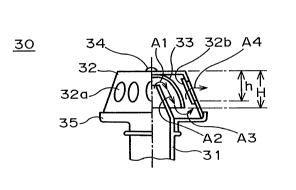
As shown in Fig. 3, the mixing tube 31 of this embodiment includes a
cylindrical portion 31a and a tapered portion 31b shaped like a truncated
cone,
and at a predetermined location on the cylindrical portion 31a, a ring-shaped
portion 31c with an enlarged diameter is formed.
The burner head 32 in this embodiment is shaped substantially as a
truncated cone with an open bottom. A number of openings 32a are provided in
the side wall of the burner head spaced at equal intervals around the
circumference, and each opening 32a is a long hole that extends in the
vertical
direction of the burner head 32. In addition, a mesh-like net 32b covers the
inside of each opening 32a (see Fig. 4).
Inside the burner head 32, an inner cup 33 is installed. The inner cup
33 is substantially hemispherical, with a diameter smaller than that of the
burner
head 32, and with an open bottom. The inner cup 33 is attached to the inner
surface of the top of the burner head 32 by means of a rivet 34 passing
through
small holes provided in the tops of the burner head 32 and the inner cup 33.
In this embodiment, the height H of the inner cup 33 is smaller than
that of the burner head 32, but as shown in Fig. 2, the height H is
predetermined
so that it is greater than the length h from the top surface of the burner
head 32 to
- 20 the bottom point of the openings 32a. More explicitly, the inner cup 33
is
arranged so that its lower rim is located below than the bottom point of the
openings 32a of the burner head 32.
The top portion of the inner cup 33 is fixed to the burner head 32 with
the rivet 34 in the present embodiment, however as long as the bottom rim of
the
inner cup 33 is located below the bottom point of the openings 32a of the
burner
head 32, the inner cup 33 can also be installed with a gap between it and the
burner head 32.
A bottom plate 35 is installed at the open bottom of the burner head 32.
8
CA 02248766 1998-09-29
The bottom plate 35 includes a mixing tube mounting portion 35a with
an inner diameter equal to the outer diameter of the cylindrical portion 31a
of the
mixing tube 31 and a flange portion 35b for mounting the burner head 32. At
the
center of the flange portion 35b, an opening with the same diameter as that of
the
mixing tube mounting portion 35a is provided, and the flange portion 35b is
formed integrally with the mixing tube mounting portion 35a. The outer
diameter of the flange portion 35b is equal to the outer diameter of the open
bottom of the burner head 32, and a vertical lip 35c is provided at the outer
periphery of the flange portion 35b. As shown in Fig. 4, the burner head 32 is
fixed on the flange portion 35b of the bottom plate 35, by being surrounded by
the
vertical lip 35c.
In Fig. 4, the mixing tube 31 is inserted into the mixing tube mounting
portion 35a of the bottom plate 35, until the mixing tube mounting portion 35a
butts against the ring shaped portion 31c with an enlarged diameter. At this
portion, the dimensions of the mixing tube 31, the burner head 32, the inner
cup
33 and the bottom plate 35 have been predetermined so that the top end of the
mixing tube 31 is located higher than the bottom rim of the inner cup 33.
The burner structure with the aforementioned construction based on
this embodiment functions as follows.
In Fig. 4 that shows the burner structure according to the present
embodiment, the mixing tube 31 is installed so it faces towards the top
portion of
the inner surface of the inner cup 33, and is installed so that the top end of
the
mixing tube 31, that is, the open end is located higher than the bottom rim of
the
inner cup 33. Therefore, the gas mixture flowing out of the open end of the
mixing tube 31 impinges against the top portion of the inner surface of the
inner
cup 33, and changes its direction of flow for the first time as shown by the
arrow
Al.
Next, the gas mixture passes down inside the space formed by the outer
9
CA 02248766 1998-09-29
wall of the tapered portion 31b of the mixing tube 31 and the inner surface of
the
inner cup 33, as shown by the arrow A2.
As described before, the height H of the inner cup 33 is predetermined
to be greater than the height h from the top portion of the burner head 32 to
the
bottom portion of the openings 32a, therefore the bottom rim of the inner cup
33 is
positioned below the bottom portion of the openings 32a in the burner head. As
a
result, when the gas mixture flows out of the inner cup 33, it impinges
against the
flange portion 35b of the bottom plate 35, and as shown by the arrow A3, the
gas
changes its direction of flow for the second time. After that, the gas mixture
rises
inside the space formed by the outer surface of the inner cup 33 and the inner
wall
of the burner head 32, and eventually as shown by the arrow A4, the gas is
discharged out of the openings 32a through the mesh-like nets 32b.
The gas mixture, discharged out of the burner structure in this way, is
ignited by a suitable means of ignition (not illustrated), and heats an object
to be
heated which is placed on the kettle holders (see Fig. 1).
According to the burner structure of this embodiment described above,
- the gas mixture first changes its direction of flow for the first time when
it
impinges on the inner surface of the inner cup 33 (see the arrow A1), and the
gas
changes the direction of flow for the second time when it impinges on the
flange
portion 35b of the bottom plate 35 (see the arrow A3). As a result of changing
directions twice, the velocity of the gas mixture decreases considerably, and
when
the gas is discharged out of the burner structure, the flow of the gas mixture
becomes substantially the same as the combustion rate.
In addition, as shown by the arrows A1 to A4, the gas mixture is
discharged from the mixing tube 31, and before the gas is discharged out of
the
openings 32a in the burner head 32, the gas changes its direction of flow for
the
first time, and then the gas descends along the inner surface of the inner cup
33,
and after the second change of direction of flow takes place, the gas rises up
to the
CA 02248766 1998-09-29
openings 32a in the burner head 32. Consequently, the gas mixture travels a
distance at least equal to the sum of the height of the inner cup 33 and the
distance from the plane of the burner head 32 to the openings 32a. This
distance
is greater than the distance traveled by the gas mixture in the conventional
burner structure shown in Fig. 2. Because the gas mixture travels over this
rather long distance together with the two changes of direction mentioned
above,
the velocity of the gas mixture is surely decreased.
Furthermore, as the gas mixture passes through the mesh-like nets 32b,
the velocity of the gas mixture is further reduced.
In this way, the flow rate of the gas mixture is decreased assuredly by
the three factors of the two changes of direction, the rather long distance
traveled,
and by passing through the nets 32b, so that when the gas is discharged from
the
openings 32a in the burner head 32, the flow of the gas is substantially
appropriate to maintain normal combustion. Accordingly, the discharge of
unburned gas mixture, caused by an excessive flow of the gas, can be
prevented,
therefore the gas mixture can be burned completely.
11