Note: Descriptions are shown in the official language in which they were submitted.
- CA 02248783 1998-09-28
Inner Transverse Ply for an Endless Elastomeric Track
Cross Reference to Related Application
This application claims the benefit of U.S. Provisional Application Serial No.
60/060,483, filed September 30, 1997.
Background of the Invention
Technical Field
The present invention relates generally to the basic structure of the flexible,
endless elastomeric track which is used on tractors and crawlers. More particularly, the
present invention relates to the arrangement of the inner transverse ply in an
elastomeric track having multiple plies of wire reinforcements. Specifically, the
invention relates to an elastomeric track having at least a longitudinal ply of main cord
wires with an inner transverse ply of laterally disposed wires extending entirely across
the main cord wires and being wrapped around the lateral edges of the main cord ply.
Background Information
Numerous agricultural and construction vehicles move about on endless tracks
that are stretched over a plurality of wheels such that relatively long, substantially flat
areas of the tracks engage the ground over which the vehicle is traveling. The tracks
are typically used on vehicles that must move about over rough or broken ground. As
CA 02248783 1998-09-28
such, the tracks are subject to a significant amount of abuse from debris commoniy
found in these environments. In addition, the tacks experience substantial forces due
to the sizes of the tracks and vehicles.
Endless tracks may be fabricated from an elastomeric material. The elastomeric
material provides numerous advantages over the metal-linked tracks of the past. It is,
however, often necessary to reinforce elastomeric tracks with reinforcing cables to
provide strength and durability to the track. One problem with manufacturing reinforced
tracks is that the manufacturer must maintain the alignment of the cables while the
track is being formed.
Providing plies of reinforcing cables in an endless elastomeric track is known in
the art to provide stability to the track. U.S. Pat. No. 4,721,498 discloses such a
reinforced track having a plurality of wire cable plies disposed to stabilize the track
during use. The disclosed track includes a first ply having longitudinally disposed wires
adjacent to a second ply of wires disposed at a positive angle with respect to the
longitudinal direction of the track. A third ply is adjacent the second ply and includes
wires disposed at a negative angle that is larger than the angle of the second ply. The
track further includes a fourth ply of wires that are laterally disposed. In another
embodiment of the invention, the patent teaches that it is advantageous to form the
second and third plies at equal but opposed angle while forming the third ply differently
than the second ply. Specifically, the patent discloses that it is advantageous to form
the third ply with fewer ends or from a smaller diameter cable. The patent teaches that
the combination of the plies substantially neutralizes the shear stresses generated from
tensile loading of the belt.
CA 02248783 1998-09-28
U.S. Pat. No. 5,211,609 discloses another reinforced elastomeric drive belt
having a plurality of wire plies disposed at opposing angles. The belt has a first
longitudinal ply adjacent a second ply that is disposed at a positive angle with respect to
the longitudinal direction. A third ply is disposed adjacent the second ply but is
disposed at a negative angle with respect to the longitudinal direction. The patent
teaches that it is advantageous that both of these angles are substantially equal. A
fourth ply is laterally disposed over the third ply. As taught is the '498 patent, the '609
patent teaches that the arrangement of these plies substantially neutralizes lateral
forces to provide balance to the drive belt.
U.S. Pat. No. 5,575,729 is another patent that discloses a reinforced elastomeric
drive belt having wire plies disposed in different orientations. This patent teaches that
two laterally disposed plies may be separated by a third ply that includes two cables
spirally wound on each side of the layer. One of the cables is wound in the S direction
(right hand spiraling) while the other wire is wound in the Z direction (left hand
spiraling). The patent teaches that this arrangement affords a balance of all lateral
forces that would negatively effect the tracking of the belt.
Although these patents disclose the desirability of creating an elastomeric drive
belt or track with pluralities of wire plies disposed to neutralize lateral forces, none of
the patents teaches, discloses, or suggests the desirability of wrapping one of the plies
over another of the plies to increase the stability of the track. Further, none of the prior
art has recognized that it is desirable to provide an inner protective ply that wraps
around the lateral edges of the main cord ply to provide additional protection to the
main cord ply. It is thus desired in the art to provide an endless elastomeric track
CA 02248783 1998-09-28
having a plurality of reinforcing plies with at least one of the plies wrapped around at
least another of the plies to improve the stability of the track.
Summary of the Invention
Objectives of the invention include providing an endless elastomeric track having
an improved ply arrangement that improves the stability of the track.
Another object of the present invention includes providing an endless elastomer
track that has increased protection of its longitudinal main cords.
A further object of the present invention includes providing an endless
elastomeric track that has a ply of transverse wires disposed inside the longitudinal
cords that protect the main cords while providing increased strength and stability to the
track.
Yet another object of the present invention includes providing an endless
elastomeric track having an inner transverse ply that wraps around the lateral edges of
the longitudinal main cords.
A further object of the present invention includes providing an endless
elastomeric track having an inner transverse ply that wraps around all of the other
reinforcing plies of the track so that the hazardous edges of the plies are covered.
These and other objectives and advantages of the invention are obtained by the
improved endless track, the general nature of which may be stated as including an
endless body having an inner surface and an outer surface, the endless body having a
longitudinal axis; a ply of main cords carried by the endless body substantially parallel
to the longitudinal axis; the ply of main cords having a pair of lateral edges, a bottom
CA 02248783 1998-09-28
surface facing the inner surface of the track, and a top surface facing the outer surface
of the track; a lateral ply of reinforcing cords disposed between the ply of main cords
and the inner surface of the track; and the lateral ply extending entirely across the
bottom surface of the ply of main cords and including a pair of wrapping portions that
wrap around the lateral edges of the ply of main cords.
Brief Description of the Drawings
The preferred embodiments of the invention, illustrative of the best mode in
which applicants have contemplated applying the principles, is set forth in the following
description and is shown in the drawings and is particularly and distinctly pointed out
and set forth in the appended claims.
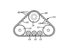
FIG. 1 is a diagrammatic side view of an endless elastomeric track according to
the present invention disposed about a plurality of wheels.
FIG. 2 is a fragmented, sectional perspective view of the endless elastomeric
track of FIG. 1 depicting the arrangement of the wire plies.
FIG. 3 is an enlarged sectional view taken along line 3-3 of FIG. 2 depicting the
end arrangement of the wire plies.
FIG. 4 is a fragmented, sectional perspective view of another embodiment of the
endless elastomeric track of the present invention depicting the arrangement of the wire
plies.
FIG. 5 is an enlarged sectional view taken along line 5-5 of FIG. 4 depicting the
end arrangement of the wire plies.
CA 02248783 1998-09-28
Description of the Preferred Embodiment
An endless elastomeric track according to the present invention is indicated
generally by the numeral 10 in the accompanying drawings. When in use, track 10 is
mounted on at least two wheels 12 that maintain the position of track 10. At least one
of wheels 12 is typically a drive wheel 14 that engages the inner surface 16 of track 10
and causes track 10 to rotate about wheels 12 and 14 in an endless fashion. A series
of lugs 18 preferably are formed along inner surface 16 of track 10 to enable wheels 12
and 14 to engage and drive track 10. Most tracks 10 further include a plurality of lugs
20 formed on the outer surface 22 of track 10 so that the vehicle using track 10 has the
traction desired by users of heavy equipment.
Track 10 includes an elastomeric body 26 wherein a calendered ply of main
reinforcing cords 28 and the plies of wire reinforcements are carried. Ply of main
reinforcing cords 28 runs continuously about the track 10 in the endless direction which
is parallel to a longitudinal axis 30 of the track 10. In the embodiment of track 10
depicted in FIGS. 1-3, ply 28 is disposed inwardly of two calendered reinforcing plies 32
and 34 such that main cord ply 28 is disposed between plies 32 and 34 and inner
surface 16 of track 10. Reinforcing plies 32 and 34 are formed from a plurality of
individual wires having a diameter that is typically somewhat smaller than the diameter
of the cords in main cord ply 28. The wires of reinforcement plies 32 and 34 are
disposed at equal but opposite angles with respect to longitudinal axis 30 of main cord
ply 28. Preferably, this angle is 35 degrees for each ply 32 and 34. The disposition of
plies 32 and 34 equalizes the lateral forces in track 10 and allows track 10 to rotate
about wheels 12 and 14 without excessive frictional forces.
CA 02248783 1998-09-28
Track 10 also has a calendered inner lateral ply 36. Inner lateral ply 36 is
disposed between main cord ply 28 and inner surface 16 of track 10. Ply 36 serves to
protect the main cord ply 28 from damage resulting from penetration from inner surface
16 of track 10. Such penetration can occur because track 10 is typically exposed when
mounted on wheels 12 and 14.
Inner lateral ply 36 is formed from a plurality of cords disposed at substantially
right angles to longitudinal axis 30 of track 10. In accordance with one of the main
features of the invention, inner ply 36 extends laterally across the entire bottom surface
37 of main cord ply 28 and wraps around each of the lateral edges 38 and 40 of main
cord ply 28 to form a pair of wrapped portions 42 and 44. Inner ply 36 then extends
partially back across the top surface 45 of main cord ply 28 with partial extensions 46
and 48. Extensions 46 and 48 are disposed between top surface 45 of main cord ply
28 and reinforcement plies 32 and 34.
Lateral ply 36 and wrapped portions 42 and 44 are spaced from main cord ply 28
by the material of elastomeric body 26. Extensions 46 and 48 extend only partially
across the top width of main cord ply 28 leaving a middle portion 50 of top surface 45 of
main cord ply 28 uncovered by lateral ply 36. In a preferred embodiment of the
invention, extensions 46 and 48 each extend approximately four to six inches inwardly
from lateral edges 38 and 40. If desirable, extensions 38 and 40 may extend entirely
across ply 28. Wrapped portions 42 and 44 and extensions 46 and 48 protect lateral
edges 38 and 40 from damage. Wrapped portions 42 and 44 and extensions 46 and
48 also provide strength and stiffness to track 10. By providing the wrapped portions 42
and 44, the main cord ply 28 is prevented from wandering during the manufacturing
CA 02248783 1998-09-28
processes.
Another embodiment of the endless track is depicted in FIGS. 4 and 5 and is
indicated generally by the numeral 100. When in use, track 10 is mounted on a plurality
of wheels (not shown) that engage the inner surface 116 of track 100 and cause track
100 to rotate about the wheels in an endless fashion. A plurality of lugs 120 are formed
on the outer surface 122 of track 100 so that the vehicle using track 100 has the
traction desired by users of heavy equipment.
Track 100 includes an elastomeric body 126 wherein a calendered ply of main
reinforcing cords 128 and the plies of wire reinforcements are carried. Ply of main
reinforcing cords 128 runs continuously about the track 100 in the endless direction
which is parallel to a longitudinal axis 130 of the track 100. In the embodiment of track
100 depicted in the drawings, ply 128 is disposed inwardly of two calendered reinforcing
plies 132 and 134 such that main cord ply 128 is disposed between plies 132 and 134
and inner surface 116 of track 100. Reinforcing plies 132 and 134 are formed from a
plurality of individual wires having a diameter that is typically somewhat smaller than the
diameter of the cords in main cord ply 128. The wires of reinforcement plies 132 and
134 are disposed at equal but opposite angles with respect to longitudinal axis 130 of
main cord ply 128. The disposition of plies 132 and 134 equalizes the lateral forces in
track 100 and allows track 100. The lateral edges 152 of the plies 132 and 134 are
somewhat hazardous during the manufacturing process because the small, individual
wires of the plies 132 and 134 protrude from their elastomeric coating and créate sharp
edges.
CA 02248783 1998-09-28
Track 100 also has a calendered inner lateral ply 136. Inner lateral ply 136 is
disposed between main cord ply 128 and inner surface 116 of track 100. Ply 136
serves to protect the main cord ply 128 from damage resulting from penetration from
inner surface 116 of track 100. Such penetration can occur because track 100 is
typically exposed when mounted on a vehicle.
Inner lateral ply 136 is formed from a plurality of cords disposed at substantially
right angles to longitudinal axis 130 of track 100. In accordance with one of the main
features of the invention, inner ply 136 extends laterally across the entire bottom
surface 137 of main cord ply 128 and wraps around each of the lateral edges 138 and
140 of main cord ply 128 and the lateral edges 152 of the reinforcing plies 132 and 134
to form a pair of wrapped portions 142 and 144. Inner ply 136 then extends partially
back across the top surface 154 of top reinforcing ply 134 with partial extensions 146
and 148. Extensions 146 and 148 are disposed between top surface 154 of and outer
surface 122 of track 100. In a preferred embodiment, extensions 146 and 148 each
extend inwardly approximately four to six inches from lateral edges 152.
Lateral ply 136 and wrapped portions 142 and 144 are spaced from main cord
ply 128 and reinforcing plies 132 and 134 by the material of elastomeric body 126.
Extensions 146 and 148 extend only partially across the top width of main cord ply 128
leaving a middle portion 150 of top surface 145 of main cord ply 128 uncovered by
lateral ply 136. Wrapped portions 142 and 144 and extensions 146 and 148 protect
lateral edges 138, 140, and 152 from damage. Wrapped portions 142 and 144 and
extensions 146 and 148 also provide strength and stiffness to track 100. Wrapped
portions 142 and 144 also protect handlers of track 100 from exposed edges 152 during
CA 02248783 1998-09-28
the manufacturing process.
In the foregoing description, certain terms have been used for brevity, clearness
and understanding; but no unnecessary limitations are to be implied therefrom beyond
the requirement of the prior art, because such terms are used for descriptive purposes
and are intended to be broadly construed.
Moreover, the description and illustration of the invention is by way of example,
and the scope of the invention is not limited to the exact details shown or described.
Having now described the features, discoveries and principles of the invention,
the manner in which the improved inner lateral ply for the elastomeric endless track is
construed and used, the characteristics of the construction, and the advantageous, new
and useful results obtained; the new and useful structures, devices, elements,
arrangements, parts and combinations, are set forth in the appended claims.
-