Note: Descriptions are shown in the official language in which they were submitted.
CA 02248828 1998-09-09
W 097/38237 PCTAUS97/05827
VIBRATION AND SIIOCK Al-l~;NUATING ARTICLES AND A METHOD
S OF AI~ENUATING VIBRATIONS AND S~IOCKST~IEREWlT~I
Field of the Invention
The present invention relates to a one-piece vibration ~tteml; ~in~ article thathas a non-tacky film covering enr,losin~ all or a ci~lifit ~nt portion of the surface of
a vibration ~ttçml~ting material, w~,ein at least a portion of the vibration
~ttçnU~tin~ material's surface covered by the film covering is a three dim~pn~ion~l
surface. The articles can be used in numerous applications where vibration or shock
~tt~nu~tion is required, inclu~ling, but not limited to, disk drive applications,
automotive applications, and electronics applications.
Bal k~round of the Invention
Vibrations and/or shocks can excite resonant frequPncies in structures.
Damping and/or isolation can be used to reduce the vibration and shock effects.
Applications where vibration and shock control are particularly hl~ ol lanl
include disk drive applications, actuator voice coil motor applications, computer
shock isolation applications, car applications, shock isolator applications for
drawers or doors, and the like.
As a specific example, resonant vibrations or shocks in a disk drive can be
caused by the read-write actuator voice coil motor assembly. An actuator is used in
a disk drive to very quickly and p~ec;sely position the read/write element over the
data track of a spinning disk. The actuator voice-coil motor design most often used
to position the tr~n~ducPr can often generate vibrations that lead to excessive
acoustical noise that is irritating to users of the disk drive. These vibrations can also
impair the positioning or stability of the read-write tr~n~ducPr over the desired data
track, thus redur.ing the drive's performance.
Fig. 1 illustrates a partial exploded view of a disk drive with only a few key
features shown for clarity. Fig. l shows top cover 2, a bottom cover 4, and a top
-1 -
, ................................... . . ...... . .
CA 02248828 1998-09-09
WO 97/38237 PCTtUS97/05827
- m~netic plate of the voice coil motor 6. A damper which would be used to damp
vibrations within the disk drive could be positioned on the top magnetic plate of the
voice coil motor 6. The damper location is intlic~ted as 8. A more detailed
description of a disk drive and actuator voice coil motor is found in U. S. Patent No.
5,224,000.
One method of damping such an actuator is to use a damper which is a die
cut part of damping material that is placed in key areas which experience vibration
to add damping to the actuator motor assembly. (See Fig. 2 where the die cut part
of d~mping material is represented by 10, the top cover of the disk drive is 2, and
the top magnetic plate of the voice coil motor is 6.) Typically, the damper is placed
b~;Lween a portion of the motor assembly and an outer surface, such as the drive's
cover or base. Known d~"~el ~ often use a damping material with a tacky surface
~soci~ted with the polymer that can make their use difficult.
Known die cut dampers are typically from 0.025mm (lmil) thick to over
3.81mrn (150 mils) thick. These die cut dalllpel~ have ess~nti~lly flat top and
bottom surfaces and straight die cut side edges that are ess~nti~lly perpen~icul~r to
the top and bottom surfaces of the damper. The vibration damper may optionally
have a polymeric film layer, for example, a die cut piece of polyester or
polyethylene film, att~hed to the damper with a p,css~re sensitive adhesive. Theadd on polymeric film covers only the top portion of the flat top damper. This
polyrneric film layer can be the same size as the damper top surface area or extend
past the top surface edges. (See Figs. 2a and 2b, respectively. ln Fig. 2a the
polyethylene film is 16, the pressure sensitive adhesive is 14, the damping material is
12, the disk drive cover is 2, and the top m~gnP~tic plate ofthe voice coil motor is 6.
In Fig. 2b the polyethylene film is 22, the pressure sensitive adhesive is 20, the
damping material is 18, the disk drive cover is 2, and the top m~netic plate of the
voice coil motor is 6.) Neither the surface of the film in contact with the damper,
nor the damper surface with which the film is in contact, is three dimensional. The
films do not offer any significant damping benefit as compared to the damping
material and the main benefit the film does provide is to provide a tack-free surface
, . ,
CA 02248828 1998-09-09
W 097138237 rCT~U~97/05827
on a single flat surface of the damper that will not bond to other surfaces it
contacts.
Two-piece "damping" constructions that use a damper and a separate die
cut film part have been used in disk drive systems where a damper (a die cut section
of darnping polymer) has a film (a polyethylene polymeric film with a pres~ e
sensitive adhesive on one side) ~ttr~ to a surface opposite from that which the
damper is placed on, such that when the drive is assembled, the damper and film are
in contact (See Fig. 2c, wl~elein the polyethylene polymeric film is 26, the pressure
sensitive adhesive is 28, the d~ polymer is 24, the top cover of the disk drive
is 2, and the top m~gn~tic plate ofthe voice coil motor is 6). The film provides a
surface to which the damper will have a fairly weak bond so that the drive can be
easily opened and reworked. The surface of this film in contact with the damper is
not three dimensional, nor does it contact a three ~limPnciQnal surface of the
damper.
Summan of the Invention
These known dampers provide for significant redllctiorlc in ~Col~ct~ noise
as well as vibration levels. However, problems with these known dampers include
the inability to use low Tg d~mring materials effectively because they may be tacky
at room t~ pe~L~Ire or at disk drive use te,,.l).,.~LLIres. Additional problems with
the current d~llpel~ include poor o lt~Ccing~ difficulty in d;.ll~.-;on~l control, etc.
These and other problems are expanded upon in detail hereafter:
1) Known dampers not used in conjunction with a polymeric film attached
opposite the dampers (See Fig. 2 ) can build a strong bond to the surfaces they
come into contact with (such as such as the cover or base surface of a drive). This
makes reworking of the drive difficult as the drive may be difficult to reopen due to
the strong bond which may have been formed.
2) A damper that has a film ~tt~hment coextensive with the top surface of
the damper, can experience "blooming" whereby the damping polymer eyr~n~ls past
CA 02248828 1998-09-09
WO 97/38237 PCT~US97/05827
- the edge of the film during use crealing a situation where the dq-mping polymer can
still create a significant bond in an undesired location. When co.,.pressed intoposition, the damping polymer expands around the film allowing a bond to form toan undesired surface (See Fig. 2d wherein the polymeric film is 30, the pressuresensitive adhesive is 32, and the ~ ping polymer is 34). Using thicker films to limit
this is not practical for thick dampers and could make the dampers difficult andmore costly to m~nllf~chlre
3) Dampers with a polymeric film (such as a polyester film) extended over
the edges of the damper (See Fig. 2b) are difficult to handle and costly to
mqnllf~ctllre as the larger film is die cut and ~tt~cl-ed via pres~u,e sensitive adhesive
to the damper or the damper is pre-cut and subsequçntly ~tt~hed via pres~ure
sensitive adhesive to the film.
4) Dampers that use a separate film die cut part attq-~hed to an opposite
surface in the drive (to prevent high degree of bonding) prior to asselllbly of the
drive require an additional part to mqmlf~ct~lre and apply to the drive (See Fig. 2c).
5) Often low Tg damping materials have a tacky surface associated with the
damping material, unless a s -fficient degree of crosclinlrin~ is present in the polymer
to render them tack-free. The polymers that have been rendered tack-free by highlevels of crosclinking (greater than or equal to about 0.5%) have a higher rubbery
region modulus than a similar polymer not so highly crosslinked. The me~hqnical
strength of the damping polymer may also be reduced due to the high level of
cross!in'-ing
These highly crosslinked tack-free polymers will not stress relax as quickly
or to as low a level as less highly crosslinked dal"~)ing polymers. This retention of
stress in highly crosslinked polymers is d~l- ill~el~lal in applications where the damper
is initially stressed upon application and to function prope- Iy, the damper needs to
stress relax (e.g., over the range of thickness stack-up assembly tolerances for the
actuator motor assembly, the high crosclinked or high Tg damping polymer may not
CA 02248828 1998-09-09
WO 97138237 PCT/US97/05827
- have sufficient relaxation in the polymer to prevent cover bowing once the cover is
att~çhçd to the base of the drive and the damper is COIII~ ssed). A tack-free
d~mring polymer may not meet all the application needs as the presence of
crosslinking may reduce the peak d~ of the dd~.,ping polymer at both room
and opelalillg telllpelal~res~
In addition, these dampers require a pressure sensitive adhesive to aid in
att~çhinp: the damper to the drive since the d~mring polymer is not tacky.
6) The current dampers which tend to be tacky at 25 to 65~ C (See Figs. 2,
2a, 2b, and 2c) can collect cor.~ tion easily and are difficult to clean either by
hand or via automatic cle~ning systems.
7) Current dampers (See Figs. 2, 2a, 2b, and 2c) can have a high degree of
ol~t~ ing This can be a problem for the enclosed en~,iro~ enl of the disk drive
where o~lt~eed materials can lead to drive reliability problems. The current
da",pe, ~ have a significant exposed surface area inside the drive and are often the
largest source of organic material in the drive. Current dalnl)el ~ may be pre-
outgPc~ed in an oven by heating the dampers to an elevated telllpe,~ re for a
period oftime. But this adds cost and complexity to the m~nll~ctllring process,
20 inçl~.din~ the potential for the dampers to become conl~;n~ted
8) The current dampers (See Figs. 2, 2a, 2b, and 2c) can be difficult to
handle as plerel,ed damping polymers tend to be somewhat tacky at room
tenlpelal~lre and most are tacky at drive opelaling ten-pela~llres. .AIltom~ted
pl~cem~nt o~such dampers can be difficult and costly due to the d~"~cl's tacky
characteristics .
9) The shapes of the current pl efel I ed dall"~c. s (See Figs. 2, 2a, 2b, and 2c)
are limited as a die cutting process is used to attain the length (X) and width (Y) of
the damper. The material used for the damper, especially as the construction
becol"es thicker and the polymer tacky, can be difficult to remove from the excess
CA 02248828 1998-09-09
W O 97/38237 PCTnUS97/05827
ing material after die cutting. This excess r~mping material, or "weed",
removal problem can limit the dampers' shapes. Dampers of square and re~ g~ r
shapes can be obtained, but other shapes such as round, tri~n~ r or "peanut't
shapes can be difficult to obtain as the damper th;~l~ness increases. Sharp co-,.ered
or small radius dampers are also very difficult to m~mlfacture and can limit thedarnpers aspect ratio for thickness versus X or Y d -....l.- ;on and also corner radius
tolerances. Dimensional control of length and width is more difficult as the damper
becomes thicker and tolerances that can be held become greater as the die cut
damper becomes thicker.
10) The exposed damping polymers of a damper can be o~citli7ed at elevated
te~l~pe~alule for short times or medi~lm te".pe-~ res at long times. Oxidation can
change the damping pl ope- lies of the damper and decrease the benefit of the
damper.
11) The exposed damping material of a damper can be exposed to harsh
en~il o~ from the air or solutions it may come into contact with during
m~mlf~ctllre or use. These harsh medillrn5 can react ~,vith the damping polymer to
reduce the benefit of the damper. In addition, reaction~ between the damping
material and the harsh en~dlol~"~ can create secondary organic compol1e,.l~ thathave a negative effect on other materials near the dampers use. Furthermore,
components or agents used in the damping material m~mlf~ct~1re may escape from
the damper and have negative effects on materials near the damper's use location.
For cA~ll~le, if the damping material uses a catalyst that can be leached from the
cl~mping material, it can cause del,in.e.~lal reactions to occur elsewhere in the area
near the damper's use location. For e,.~"ple, a component that leaches or
outg~cses onto the storage disk's surface from the damping material could lead to
corrosion of the disk surface area.
12) The exposed damping material of current dampers does not have a high
degree of wear or abrasion characteristics. This limits the dampers use to
CA 02248828 1998-09-09
W 097/38237 PCTrUS97/05827
applications where the damper is not ~".pGsed to abrasive or wear type
envi.o.. - -.ls. Wear or abrasion could be induced by repeated contact ofthe
damper to other objects or exposure to a flow of material (fluids such as air, water,
etc.).
The ~~-ecl-~nicm by which current dampers ~ic~ A~le undesirable energy by
d~mring resonant vibrations, involves de~.l..aliol~ or sl~ail~ing ofthe ~
material. That is, when the structure that the damper is applied to is subjected to
cyclic loading, for example, the d~nrin~ material is subjected to tension-
co~ ession de~.l.~ion and diecipates the energy through an extensional strain
mecl~ni~.., In addition, damping can occur by energy ~icsiration from the da-~ gmaterial via a shear .~Çl~ 5.~ that results from consll~.nl created by the damper
being placed between two structures (for example, an actuqtor motor and cover orbase). The dampers can also act as isolators by reducing the vibration l~ c~n;~
from a vibration or shock source to the structure on which the dampers are beingused. The peak shock and /or vibration energy or peak acceleration is reduced byuse of the damper.
Although the current dampers used in drives are reasonably effective, the
problems in using the dampers with a tacky damping material can be difficult and as
the drive requirements for ~leAnl;neSC, out~ccingJ ease of application, etc. become
more restrictive these probl_llls could limit the use of the d~pe~ s. Thus, an
alternative approach is needed to damp vibrational or shock energy without
negative effects of the current dampers.
Summary of the Invention
The present invention provides a novel attçnll~ting article that can overcome
the negative aspects of the current d~l.l)cl ~, and even offer the potential forimproved ~mping and isolation perforrnance.
~ , .
CA 02248828 1998-09-09
W 097/38237 rCTAJS97105827
- The novel article ofthe invention conl~JIi3e,s
(a) a vibration ~ttçn~ting material, wherein the vibration ~ltten~ ting
material has a storage modulus greater than about 6.9x10³ Pascals and a loss factor
greater than about 0.01 at 25~C and 1 Hertz, wherein the vibration ilttemJ~ting
material has a surface and an interior;
(b) an exterior film covering, wherein the exterior film covering film has a
tensile modulus greater than about 6.9x10³ Pascals at 25~C and 50% relative
humidity, wherein the exterior film covering co~ ises one or more of the
following:
(i) a film;
(ii) a film segm~nt;
wherein the vibration ~tten.l~tinE material surface is at least partially
enclosed by the exterior film covering;
whel ein an inner surface of the exterior film covering col~",ls to the
surface of the vibration ~ttPn~)~ting material that it is at least partially enclosing;
wherein at least a portion of the surface of the enrlosed vibration
~ttenu~ting material has a three dimensional shape;
(c) optionally one or more interior film dividers, wherein each interior film
divider has a tensile modulus greater than about 6.9x10³ Pascals at 25~C and 50%relative hurnidity, wherein each interior film divider co"l~,lises one or more of the
following:
(i) a film;
(ii) a film seg~..P~
wherein each interior film divider separates at least a portion of the vibrationatten-l~ting material from another portion ofthe vibration ~tt~n-~ting material; and
(d) optionally a layer of adhesive coated on one or more of the following:
(i) at least a portion of a surface of the exterior film covering;
(ii) at least a portion of a surface of any interior film divider, if
present;
(iii) at least a portion of any vibration att~n~1~ting material which is
not enclosed by the exterior film covering.
CA 02248828 1998-09-09
W O 97/38237 PCT~US97/05827
- wherein when the vibration ~ttçn~tin~ material is completely enclosed by
the exterior film covering a layer of adhesive is coated on at least a portion of an
outer surface of the exterior film covering.
S The exterior film covering is des~;.ibed herein as having two surfaces, an
inner surface which is in contact with the vibration atten~ting surface and an outer
surface which is its surface which is not in contact with the vibration ~ttçn~ting
material.
An embodiment ofthe article ofthe invention is that wherein at least one
interior film divider has multiple layers, wherein at least two of the layers have
di~~ g chemical compositions.
The present invention also provides a method of ~ttçnu~ting vibration in a
structure comprising the step of po~itioning an flttçn..~ti~ article in relation to the
structure such that the attçnu~tin~. article is capable of ~tt~nu~ting the vibration of
the structure in at least one vibrational mode, wherein the ~ttenu?ting article
comprises:
(a) a vibration ~tten-l~ting material, wherein the vibration att~n~ting
material has a storage modulus greater than about 6.9x10³ Pascals and a loss factor
greater than about 0.01 at 25~C and I Hertz, wherein the vibration atten-J?tin~
material has a surface and an interior;
(b) an exterior film covering, wL.ein the exterior film covering film has a
tensile modulus greater than about 6.9x10³ Pascals at 25~C and 50% relative
humidity, wherein the exterior film covering comprises one or more of the
following:
(i) a film;
(ii) a film segm.o.nt;
wherein the vibration atten~tin~ material surface is at least partially
enclosed by the exterior film covering;
wherein an inner surface of the exterior film covering con~o""s to the
surface of the vibration ~tteml~ting material that it is at least partially enclosing;
.. . . , . ~ . . . .. .. .. ~ .
CA 02248828 1998-09-09
W O 97138237 PCTAUS97/05827
- wherein at least a portion of the surface of the enclosed vibration ~tt~nl~tin~
material has a three dimensional shape;
(c) optionally one or more interior film dividers, wherein each interior film
divider has a tensile modulus greater than about 6.9x10³ Pascals at 25~C and 50%relative humidity, wherein each interior film divider ~~ Jl ises one or more of the
following:
(i) a film;
(ii) a film segm.~nt;
wLcrein each interior film divider 5ep~aleS at least a portion of the vibration
damping material from another portion of the vibration damping material; and
(d) optionally a layer of adhesive coated on one or more of the following:
(i) at least a portion of a surface of the exterior film covering;
(ii) at least a portion of a surface of any interior film divider, if
1 5 presen~,
(iii) at least a portion of any vibration ~tten-~qting material which is
not enclosed by the exterior film covering.
A p~relled method is that wherein the vibration amplitude ofthe structure
has been reduced by at least about 10% in one mode.
The exterior film covering is described herein as having two surfaces, the
inner surface which is in contact with the vibration att~nu~ting surface and the outer
surface, which is its surface which is not in contact with the vibration ~ttçml~ting
material.
Preferably the structure in the above listed method is selected from the
group consisting of disk drive assemblies, optical disk drives, compact disk
assemblies, appliances, ~ sl)ol L vehicles, automobiles, doors, drawers, hoods,
computers, test equipment which is sensitive to shock or vibrations, and the like.
As a specific example, an article of the invention, when used to damp a disk
drive, may be placed between the top magnet plate of the actuator voice coil motor
assembly and the disk drive top cover. The vibration ~ttçml~tor is typically placed
CA 02248828 1998-09-09
WO 97/38237 PCT/US97/05827
- under 140 percent co~ ress,on when the cover is ~tt~rhed to the base of the drive.
The damper could also be placed, for example, between the bottom magnet plate
and the base of the disk drive. This damper location may not have ~ignifir~nt
co""),~ssion, but the damper does contact the base of the drive and the bottom
-
S magnet plate. U.S. Patent No. 5,224,000, provides additional detail regalding disk
drives.
Another embodiment of the method of the invention is that wherein the
structure is a disk drive assembly, wherein the article is positioned between anactu~tor and a surface opposite the actl~tor such that the article can be contacted
by the actuator during actuation.
As another example, an article of the invention when used to isolate a disk
drive a~tu~tor may be placed between an edge surface ofthe voice coil motor,
typically on the coil of the voice coil motor or the side edge of the "E-block"
asscl"bly used to support the read/write çlemçnts~ or on a surface opposite the coil
or " E-Block" assembly, when the voice coil motor is actu~ted or is subjected toexcessive vibrations or shocks allowing the actuator to i.~ ge against a surfacewith the article, the article of the invention ~ttenu~tçs the vibration or shock.
As another example, an article of the invention can be used to isolate a door
or drawer when the structure is opened or closed, (i.e. actu~ted in the door or
drawer frame thus producing a vibration or shock). The article may be placed on the
door or drawer at a location that will contact the structure the door or drawer is
being impinged against. The article of the invention will attçm.Ate the vibration or
shock energy and reduce the acoustical noise and vibration level.
The present invention also provides a structure having an Att~nuating article
positioned in relation to the structure such that the atten.~ting article is capable of
attenll~ting the vibration of the structure in at least one vibrational mode, wht;~t;in
the article comprises:
(a) a vibration attçn~l~ting material, wherein the vibration ~ttçn~l~ting
material has a storage modulus greater than about 6.9xl o3 Pascals and a loss factor
greater than about 0.01 at 25~C and I Hertz, wherein the vibration attçn-lAting
material has a surface and an interior;
.. ~ .. .... . .
CA 02248828 1998-09-09
W O 97138237 PCTAUS97/05827
(b) an exterior film covering, wherein the exterior film covering film has a
tensile modulus greater than about 6 9x~03 Pascals at 25~C and 50% relative
humidity, wherein the exterior film covering comprises one or more of the
following
(i) a film;
(ii) a film seen.ç~ l,
erein the vibration ~tt~nU~ting material surface is at least partially
enclosed by the exterior film covering;
wherein an inner surface ofthe exterior film covering sllbst~nti~lly col~lms
to the surface of the vibration attçno~tine material that it is at least partially
enclosing;
wherein at least a portion of the surface of the enclosed vibration ~ttçn~l~tinematerial has a three di...c;l.s;onal shape;
(c) optionally one or more interior film dividers, ~hel ein each interior film
divider has a tensile modulus greaterthan about 6 9x10³ Pascals at 25~C and 50%
relative humidity, wherein each interior film divider colllplises one or more of the
following
(i) a film;
(ii) a film seg~
wherein each interior film divider separates at least a portion of the vibrationd&,..ping material from another portion of the vibration damping material;
(d) optionally a layer of adhesive coated on one or more of the following:
(i) at least a portion of a surface of the exterior film covering;
(ii) at least a portion of a surface of any interior film divider, if
prese..l,
(iii) at least a portion of any vibration ~ttçnu~tine material which is
not enclosed by the exterior film covering
CA 02248828 1998-09-09
W 097138237 PCT~US97/05827
- Definitions
The term "atten~tQr" as used herein inchldes dampers, isolators, and
co...l~;l.dlions thereof that dicsipate vibration energy and/or shock and/or change the
S vibration and/or shock ll~ns~ ed to a structure that it is used with, in or on.
The terrn ''atten~1atine material" as used herein refers to a material that
provides vibration and/or shock energy dissipation and/or shock and/or vibrationisolation improvement.
The novel articles of the present invention overcome the many shortfalls of
current damper designs by having the following design and application advantages:
1) An optimum vibration ~tten~l~tine material can be used for a given
application, without the Tg, and thus the potential tac~in~ss of the material
nfceSs~ ily being a limiting factor to the design or use of the novel article. The
novel article design provides for partial or complete enclosure of the attç~ ting
material to limit negative effects of using a plere-led vibration ~ttçm.~tine material.
2) The novel articles can be desiened such that they ~,vill not experience
negative "blooming" effects as some current da~ e. s do. The exterior film covering
may cover the vibration atten~ating material completely or to a large extent andprevent the vibration ~ttçn.l~tine material from blossoming around the exterior film
covering and creating contact with an undesired surface.
3) The novel articles of the invention do not require a film e~t~qn~1ing away
from the attPn..~fine material surface to prevent blooming around the film edges as
some existing dampers use. The current dampers that use a film extçn-ling away
from the damping material surface are expensive to m~nllfac.t~lre, difficult to handle,
and complex to m~nllf~ctllre.
CA 02248828 1998-09-09
W 097/38237 PCTrUS97/05827
- 4) The novel articles of the invention are a unitary design. Single piece
construction reduces application costs as con~pared to the current two-part damper
used in many disk drives.
5) The novel article of the invention allows tacky vibration ~ttçn~ting
materials having low Tgs and/or low crocclinking levels to be used. The novel
article can çlimin~te the proble~ associated with using the optimum tacky vibration
s~ttçnll~tin~ materials for a damper. Previously, some dampers have overcome some
of the current damping material problems (for eY~n ple the tacky characteristic of
the darnping material at application or drive opel dlhlg temperature), but in doing so
they created new problems by using high modulus (high Tg, high cross-linking)
d~..ping materials which have minim~l stress relaxation and thus retain a significant
amount of stress when cor..l~essed. As many appli~tion~ require stress relaxation,
for example, to prevent the disk drive cover from being bowed during or after the
dampers application, the high Tg damper is not acceptable for many applications.Plus, the damping pe,r~",lal1ce ofthe damper is less than Oplilllulll.
6) The novel articles of the invention can potentially use an optimum
vibration ~ttçnll~ting material which may be, for example, a tacky material and
.. ~ ;.. i7f': collection of co,.l~n~ ion, as a ci~nifi~ n~ portion ofthe surface ofthe
article may not be tacky dependillg on the size of the exterior film covering. In
addition, the novel article may, depel1dillg on its design, be effectively cleaned by
hand or in automatic cle~ning systems. The current gene,~ion vibration ~tt~n--~ting
materials are not easily cleaned and collect co..l;....il-~l;on (dust, debris, etc.) easily
as a tacky surface is often related to the da.l.pin~, material. As a damper may need
to be clean to a level s~-ffisient to meet a clean room deci~n~inn of Class 1 or Class
l O0, the novel article of the invention is particularly advantageous.
7) The novel articles of the present invention can use films that act as
barriers to components out~c~in~ from the vibration ~ttçn~l~tin~ material
(examples include unreacted monomers, impurities, small molecular weight reaction
-14-
CA 02248828 1998-09-09
W 097/38237 PCTrUS97/05827
- components such as alcohols, catalysts such as those based on tin or pl~timlm, etc.).
The o~lt~csing components may have a reduced surface area from which to escape
as col.lpared to conventional da.llpel~ wherein the vibration ~tt~n~ting material is
not enclosed as in the article of the present invention. The exposed areas of the
S vibration ~qttPn-~ting material can also be signifir~ ltly less than for the vibration
~ttP.n-~?tin~ material of a current damper.
If pre-outg~sci~ should be needed for the novel articles of the invention this
also can be accomplished, but with the added benefit that the vibration ~ttçn.~ting
material is generally not exposed and thus will not collect debris if o~tg~c~ed on a
convection type air heated oven. The novel article design is also less likely to absorb
undesirable components that the articles may be exposed to during cle~ning,
sllil)pillg, h~nflling and m~nufactl1re and that could outgas at a later time.
8) The article of the invention is easily positiQnp~d by hand or by the use of a~P~~ device such as tweezers, graspers, etc., with little or no limit~tion basedon the type of vibration ~tten~ting material used in the article. ~ltorn~ted devices
may also be used to position the article of the invention. Current dampers can be
difficult to handle and efforts to automate their p!rc~PnnPnt would require special
methods to handle a tacky attçn~l~tin~ material.
9) The novel articles of the invention can have a plethora of shapes and
provide greater ranges for dimçmion~ and aspect ratios than known dampers. The
novel articles may optionatly have one or more of the fotlowing features: holes,25 multiple contours, ridges, raised portions, flat surfaces, protrusions, convex
features, concave features, and flaps of film at the article's edges. These features
allow the article to be custom shaped for specific applications and can atlow the
article to have less conventional shapes to aid in locating the part for assembly or
inspection.
CA 02248828 1998-09-09
W 097/38237 PCT~US97tO5827
- 10) The articles of the invention can have up to 100% of the vibration
~ttçnll-tin~ material surface covered by the exterior film covering, thus improving
the oxidative rçcict~nce ofthe vibration ~ttçnu~ting material at elevated tclllpclalLlre
for short times or at mPAillm tclllpel~llJres at long time. The vibration attçn~atin~
5 mater.ial may be sub~l~llially or completely protected from oxidative deterioration
(depending on the size and characteristics of the exterior film covering, etc.), and
thus is more likely to retain its vibration ~ttçn~ tin pr~pel Lies.
Oxidation is d~tl il..clltal in that it can change the prop~ ies of the vibration
~ttçnu~ting material of the article and decrease its benefits. The use of the exterior
10 film covering can also allow the use of a vibration att~nu?tine material which is
substantially free of oxidation inhibitors (antioxidants, for example). The ç~ ion
or reduction of antioxidants and other rhçmic~ to çl~h--nce the thermal oxidative
stability of the vibration attçnu~tin~ material used in the novel article of theinvention can allow for the use of a less costly danl~ g material, a material which
experiences less oul~,~c~ as well as a material which has a higher polymerization
degree and which can be p. cpal ed via a faster reaction conl~al ed to those materials
which contain oxidation inhibitors.
Further, the novel articles of the invention may utilize films of multiple
layers. The multiple layers can improve the barrier p~o~>el ~ies of the film(s) layer.
They can also provide good conrolll,ability to the vibration ~tt~mlS~ting material and
also reduce the stiffnçs~ of single layer film. For eAa,lll~le, a film 6 mils (0.1 5mm)
thick may be stiffer than a tri-layer film of three layers each 2 mils (0.051 mm)
thick, each layer separ~ted by an adhesive layer or otherwise bonded to each other
with a lower modulus material. Multiple layers bonded together via a vibration
~ttçm-~tin~ material may also improve the vibration attçnl~ ting ability of the article
as col,.pared to a single film layer.
The use of an exterior film covering which may cover a large portion or all
of the vibration att~nuatin~ material may also lead to inc~ eased shearing of the
vibration atteml~ting material in shearing and co"-p-t~sion-tension modes. Thus
improved damping may be achieved by the use ofthe novel article over the
conventional damper.
-16-
CA 02248828 1998-09-09
W 097/38237 PCTrUS97/05827
- Protrusions ~oYt~.nrlinp from the exterior film covering into the vibration
attçnu~tin,~ material can also improve the shearing effect in the vibration ~ttenu~ting
material and further increase vibration ~ttenwtisn A portion of the resulting
meçh~nical strain energy in the vibration attçn-~ting material is then ~lissipqted in
the form of heat. The higher the strain energy into the vibration ~tt~nu~ting
material, the more vibration energy is ~icQip~ted from the system in which the article
is used.
1 l) The novel article ofthe invention may have increased enviro~
l 0 survivability with the use of various wear/abrasion, çh~mi~lly, thermally and
radiation (for e.~nple, ultraviolet or infrared radiation) resistant films and/or film
se~..e~llc. The novel articles ofthe invention may have improved resict~nce to
harsh envirnn~ c such as gases or solutions they may come into contact with
during m~nllf~cture or use. These harsh m~il mc can react with exposed vibration~ttçmls~ting material to reduce the benefit ofthe article. In addition, reactions
bel~een the vibration ~ttenU~ting material and the harsh envil onl"~lll can create
secondary co,.")onenls that may have a negative e~ect on other materials near the
article's use location.
Furthermore, components or agents used in the vibration ~ttçn~ ting
material m~mlf~ctllre may escape from the artide and have negative effects on
materials near the article's use location. For example, if the vibration ~ttçml~ting
material uses a catalyst that can be leached from the vibration ~ttçm~tin~ material,
it can cause d~L,hl,~"Lal reactions to occur elsewhere in the area near the article's
use location.
12) The novel article of the invention can be desig1led to have a high degree
of wear or abrasion recist~nce. This improved wear and abrasion re~ict~nce expands
the article's use to applicaLions where the current generation dampers are not
utilized because of conc~ s l egardh~g abrasion or wear. Wear or abrasion could be
in~uced by contact of the article to other objects or exposure to a flow of material
(fluids such as air, water, slurries, etc.).
CA 02248828 1998-09-09
W O 97/38237 PCTrUS97/05827
Brief De~ tion of the Drawin~s
Fig. I illustrates a partially exploded view of a disk drive showing a location
where a damper could be used.
Figs. 2-2d illustrate cross-sectional views of prior art d~.l~)e~ ~.
Figs. 3a-31 illustrate top plan views of embodiments of the articles of the
invention.
Figs. 4a-4m illustrate cross-sectional view of emborlim~nts of the articles of
the invention.
Figs. 5a-5h illustrate cross-sectional view of embo.iim~onts ofthe articles of
the invention.
Figs. 6a-6c illustrate cross-sectional view of embodim~nts of the articles of
the invention.
Figs. 7a-7c illustrate cross-sectional view of emb~diments of the articles of
the invention.
Figs. 8a-8d illustrate cross-sectional view of embodimçnt~ of the articles of
the invention.
Figs. 9a-9d illustrate cross-sectional view of embodiments of the articles of
the invention.
Figs. 1 Oa- 1 Oc illustrate cross-sectional view of embodiment~ of the articles
of the invention.
Figs. 11 illustrates a cross-sectional view of an embodiment of the article of
the invention.
Detailed Dcrc. ;~tion of the Invention
ARTICLE S~APES
The article of the invention, as well as the vibration ~ttçnu~tin~ material,
may have a variety of shapes. The shapes may or may not be symmetrical.
Ex~ples of suitable shapes include but are not limited to those selected from the
group consisting of polyhedrons such as cubes, rings, pyramids, prisms, trunc~ted
CA 02248828 1998-09-09
WO 97/38237 PCT/US97/05827
- pyramids, stepped pyramids, stepped le~ gles~ etc., and other shapes such as
cylinders, cones, spheres, hçmi~pheres, pillows, etc.
The article may optionally have at least one flat surface which may be used
to mount the article for its intended applicalion. This surface typically has anadhesive (most typically a pressure sensitive adhesive) coated thereon to aid inmounting the article. The adhesive may be coated onto any exposed vibration
~tteml~tin~ material and/or the outside surface of the exterior film covering that
encloses the vibration ~tten-~ting material. The exposed vibration ~ttenl~tin~
material may possess adhesive cha, _~ :eristics itself and thus could aid in adhering
the article to a surface if desired.
EXTERIOR FILM COVERINGS AND INTERIOR FILM DIVIDERS
The exterior film covering co,.,p~ ises one or more films and/or film se~ s
of various p- UpCI Lies. Likewise, the interior film dividers may comprise one or
more films and/or film seg.n~ of various prope~ ~ies. These films and/or film
se~ n~ may have the same or d;rre~e.l~ che".c~l compositions, ~ n~ n~
(thickness, widths, lengths) etc. These films and/or film se.e~ may adjoin,
overlay, overlap each other, etc. These film(s) and/or film se ,,.~nl(s) may be
contim~o~ls or discontinuous, with or without perforations, holes, and/or slits, etc.
Likewise the exterior film covering and the interior film dividers may be continor discol,~ ous, with or without pe~rulalions~ holes, and/or slits, etc. The exterior
film covering and the interior film dividers, as well as each film and/or film se~n~nt
which make them up, may optionally have various degrees of surface roughn~c in
order to modify the article's pe~rc"".dl~ce.
Various films and/or film seg,.~ may be used in the exterior film
coverings and internal film dividers. The films and/or film seg...-...ls may be woven
and/or non-woven. For example, the non-woven could be a hot melt blown micro-
fiber of polypropylene and/or polyester. The films and/or film seg. . .~nl ~ mayoptionally be porous. Polymeric and/or non-polyrneric films and/or film seg. .~nl S
may be used. E~l,ples of suitable polymeric films include but are not limited tothose selected from the group consisting of polyester, polyimide, polyamide,
-19-
.
CA 02248828 1998-09-09
W 097/38237 PCT~US97/05827
- polyethylene, polypropylene, acrylic, phenolic, polyvinyl chloride, polyurethane,
polystyrene, fluorinated polymer films (such as those available under the trademark
Teflon from DuPont), polyvinyl acetAtes, nylon, etc. Useful non-polymeric films
and/or film seg~ include but are not limited to those selected from the group
cons;sling of ~ min~m gold, silver, ~IA;~IeSS steel, copper, brass, etc. Amorphous
polyester is a ylerelred film.
The films and/or film se~ c may optionally be metAli7e-1, corona treated,
pi~m~nte~l, provided with a release surface, provided with a surface capable of
~i~cip~ting static electricity, provided with a reflective surface, provided with an
adhesive surface, provided with environm~nt~l re~:~lA.-ce (i.e. re~;C~A.-ce to heat,
hurnidity, chemicals, radiation, and/or vacuum effects, etc.), provided with wear or
abrasion res~ nce, provided with co...; ~ ity (envirol.n~e~ lly, ...ecl1Ai-:c.~lly,
and/or chemicAlly) with a plal~ed surface that it will cont~ct, provided with a low
energy surfaces, provided with ~ceol~s and/or liquid barrier properties, and/or
provided with thermal and/or electrical con~ c.tivity in order to provide an exterior
film covering and/or internal film divider having such prope. Iies. The films and film
segJnentc may be coated with various c~tingS such as epoxies, waxes, silicones,
fluoropolymers to impart release characteristics or low energy surfaces to the
exterior film covering and/or the interior film divider. The films and/or film
se,~,,.. ~l-l s may optionally be hl~yr~ Aled with various materials to modify their
propel ~ies (such as fillers, tough~ning agents, colorants, fibers, partiC~ te~ etc.) The
film and/or film se~m~nt p-ope- Iies may be localized to specific areas if desired.
Different films andlor film seg~ 1 s may be used to provide an exterior film
covering or an internal film divider with di~l elll pl opel Iies. For example, the
exterior film covering may comprise two layers which can be identified as an inner
film and an outer film. An inner film may be selected to which the vibration
~tten-~Atin~ material readily adheres while the outer film of the exterior film
covering may be selected which provides better exterior wear characteristics to the
damper (such as scuff resislance). Other exterior film coverings are possible. The
exterior film covering may co,,,yl;se one, two, three, four, five, or more layers of
film and/or film se~n~ Likewise each interior film may comprise one, two, three,
-20-
CA 02248828 1998-09-09
W O 97/38237 PCTrUS97/05827
-four, five, or more layers of film and/or film seg,..~ . As another eA~Ilp1~ the
exterior film covering may have inner and outer layers which are the same, but amiddle layer which is dil~ wll. If the exterior film covering co",p, ises more than
one film or film se~ l the films and film se~nPnts may optionally be bonded
togeth~r via an adhesive such as a pressure sensitive adhesive or otherwise
optionally bonded together by other means. The same potential for bonding also
applies to the interior film dividers.
Other ~ ..ples include a three layer exterior film covering construction
comprising a low density/high densityllow density polyethylene construction, a low
density /me~ m density Aligh density polyethylene construction, and a low density
polyethylene/high density polyethylene/low density polyethylene. One or more of
the afol e~ nlioned film layers may cptionqlly be thermally or electrically
conductive. The exterior film covering may also co",p,;se, for example,
constructions of polyester/polyimide or acrylic/polyester or polyethylene/polyamide,
1 5 etc.
The article of the invention may optionally have one or more i~pl ei,;,;ons
therein in order to aid application, assembly or ide-ntific~qtiQn of the articles for
m~mlfqctllrer, end-user, application, etc. The h~ples~ions can be made in one ormore ofthe following: the eAterior film covering, the vibration qtt.on--qting material,
the interior film divider(s). An eAa"")le would be an idçntific.~q-tion logo to identify
the end user.
As mentiorled previously the vibration attenl~-qting material may be partially
or completely enclosed by the exterior film covering. When the vibration
~qtten~l~ting material is partially enclosed by the exterior film covering typically
about 50 to about 99 percent of the surface of the vibration ~tteml~ting material is
enclosed by the exterior film covering, more typically about 60 to about 90 percent,
and most typically about 65 to about 85 percent.
The exterior film covering may optionally have features such as protrusions,
hll~ ,ss;ons, etc. These features may be on the side of the exterior film covering
contacting the vibration attçn--~tin~ material or on the side of the exterior film
covering not cont~cting the vibration ~tten~tin~ material, or both. These fealules
... . .. .
CA 02248828 1998-09-09
WO 97/38237 PCT/US97/05827
- may impart various potential pel rO, ~llance characteristics to the article or aid in its
intentled end use. The protrusions can also improve the bonding or adherence of
the film to the ~ttenu~ting material. Likewise the interior film dividers may have
such features on either or both sides thereof.
The exterior film covering encloses the vibration ~tt~n.l~tin~ material. A
surface of the exterior film covering that contacts the vibration attçn-l~ting material
is considered to be an inner surface, whereas a surface of the exterior film covering
which does not contact the vibration ~ttenlJ~ting material is corlQidçred to be an
outer surface. Some designs allow for one film to fi~nctiQn as an exterior film
covering for a sections(s) ofthe article where it encloses vibration ~ttenl~tin~material by only one of its sides but as an interior film divider where it is contacted
on both of its sides by vibration ~ttçn-~tin~ material. This concel)l is furtherexpl~ined in the discussion of the Figures.
Optionally two or more of the articles of the invention can be joined
together by or through their exterior film coverings. (for example one continuous
film may serve as part of the exterior film covering of two or more articles).
Optionally two or more of the articles of the invention may be adhered together
either via an adhesive or via exposed vibration i~ttçnn~ting material.
The adhesive layer can co,,ll,l ise one or more layers of adhesive which may
be the same or di~ere,lL. The adhesive layer may for eA~ !e, be fully cured or
partially cured. Exallll)les of suitable adhesives include but are not limited to those
selected from the group consisting of pressure sensitive adhesives, epoxies,
structural epoxies, and the like. The adhesive layer may be contimlo~-s or
discontinuous.
VIBRATION ATTENUATrNG MATERIALS
The term "vibration ~tt~nu~tin~ material" as used herein incl~ldes vibration
damping materials, vibration i~o!~tin~ materials, colllbh,alions thereof, etc.
The vibration and/or shock Atten-l~tinp~ material can include any material that
is viscoelastic. A viscoelastic material is one that is viscous, and therefore capable
of dissipating energy, yet exhibits certain elastic propel lies, and thererore capable of
storing energy. That is, a viscoelastic material is an elastomeric material typically
CA 02248828 1998-09-09
W 097/38237 PCTAUS97/05827
cGn~ inp long-chain molecules that can convert n~ecl~ ical energy into heat whenthey are deformed. The viscoelastic material can also be designed to have the
desired elastic characteristics needed to provide isolation propcl lies and a lower
level of dan~pin~ than as used in a design where damping is a primary design
S objective. Such a material typically can be de~l,lled, e.g., stretched, by an applied
load and gradually regain its original shape, e.g., contract, so~net;...e after the losd
has been removed.
Additives such as flame retardants, anti~xid~nts, fibers, anti-static additives,particulate and colorants can also be added to the ~tten~ting material to impart specific pwro.~ ce features.
The viscoelastic ~ttçn~ting material useful in the invention can be a
thermoplastic polymer or a thermoset polymer or co...bh~alion of both fully or
partially cured. Thermoset polymers, while useful as viccoel~ctic ~ttçn~ting
materials, are used less often than ll.e....o~l~cl;c polymers due to their lower15 e~ective te,,,pelal~lre range of high damping. Ple~lably~ the viccoelS~ctic
~ttçn~tinP material is a thermoplastic polymer, such as an acrylate.
Suitable viscoelastic materials for use in the vibration ~ttçn-~ting materials
ofthe present invention have a storage mo~ us, i.e., measure ofthe energy storedduring dero,...alion, of at least about I psi (6.9 x 10³ Pascals). The storage
modlllllc of useful viscoelastic materials can be as high as 500,000 psi (3.45 x 10⁹
Pascals); however, typically it is about 1-2000 psi (6.9 x 10³- 1.4 x 10⁷ Pascals).
Suitable viscoelastic materials for use in the vibration ~ttçn-l~ting materials
of the present invention that have as a primary design goal damping, have a lossfactor, i.e., the ratio of energy loss to energy stored, of at least about 0.0l .
Preferably the loss factor is at least about 0.1, more preferably about 0.5-10, and
most preferably about l-10, regardless ofthe frequency and temperature
experienced by the material. Suitable viscoelastic material for use in vibrationattem~tion materials of the present invention that have as a primary design goalisolation, have a loss factor of less than l .0, preferably less than 0.3-0.5 and most
prere,dbly less than about 0.1. An ~tten.~tor design material should be sçlectedthat allows the isolation level required to be a~' ~cd, along with the minim~m
.. .. ..
CA 02248828 1998-09-09
WO 97/38237 PCT/US97/05827
ing needed to allow control of the desired resonanl frequ~Pncies ( if the
material is available).
This loss factor ~ep.esenls a measure ofthe energy tliCcip~tion ofthe
material and depends on the frequency and te~ re experienced by the
~ttçn~7tinp material. For example, for a lightly cros~linlçd acrylic polymer with a
Tg of about 5~C, at a frequency of 1 Hz and a primary design goal of dal..ping, the
loss factor at 68~F (20~C) and 1 Hz is about 1.0, while at 1 58~F (70~C) the loss
factor is about 0.7. As the Tg of a material is also an in-lic~tor of the potential for
the d~.,ping material to have a tacky or sticky characteristic, especi~lly if the
10 ~ttenllating material is only lightly crosslinked, the aforellJt;~ oned acrylic damping
material is very tacky at 25~C.
~ ttem~ting materials that have high Tgs (Tg >60~C at a frequency of 1 Hz)
are known. However, these higher Tg materials may have less capacity to add
d~ ril-g to the system at the use t~lllpelalure (for t.~ lple, the typical driveopelaling te,llpel~lure range of 5~C to 65~C). Thus, ~ttPn~l~tin~ polymers with a Tg
greater than 60~C may have limited benefit for most disk drive applications. Thus,
the optimum ~ttPnu~tor for a drive actuator application uses an attenl)~ting material
with a Tg less than about 60~C (at a typical drive op~;ldling te..,l~e~L~lre of 5 to
65~C) and most preftl~bly an ~ttem~qting material with a Tg less than about 45~C at
20 a frequency of I Hz, and most preferably an att~nu~tin~ material with a Tg less than
about 38~C at a frequency of 1 Hz.. This damper will tend to be tacky and build a
strong bond to most surfaces it comes into contact with (stainless steel, ~luminllm~
epoxy co~tingc, etc.)
The material se~ected for use in an isolator design that has vibration or
shock isolation as the pJ;I~laly design objective, will typically have less damping
(lower loss factor) than material for a design where vibration dal,l~ lg is the
primary design objective.. This is because an und~mped material is superior to adamped material in reducing trancmicsibility. However, reduction in lli.n~ ccibility
occurs only for frequencies greater than the square root of 2 times the natural
frequency ofthe isolator, v. The.e~ore, the material must have an amount of
-24-
CA 02248828 1998-09-09
W 097/38237 PCT~US9710S827
- domping sufficient to reduce structural le30na"l amplitudes for resonances
occurring below v to an acceptable level.
Preferred vicco~lqctic materials are those that remain functional over a wide
range oftemperatures, e.g., -60~F (-51~C) to 600~F (315 ~C). Most prt;rel~ed
S viscoelastic materials are those that cover the broadest te,.,l)cr~lure and frequency
range at the desired loss factor and storage m~ us to achieve acceptable
attçnu~iorl of the item that the ott~nUotQr of the invention is being used to darnp,
isolate, or both and do not CAp~l iellce a significant degradation in prop~, lies due to
long times at high tenlpel alures or short excursions beyond these high ten~i)G, al~re
levels.
Useful viscoelastic ott~n--~ting materials can be is~l~op.c as well as
anisollopic materials, particularly with respect to its elastic prope, lies. As used
herein, an "anisotropic material" or "noni30l10p c material" is one in which theprope, lies are depende~.l upon the direction of ~"e&s.lre."~l. Suitable viscoelastic
materials include urelhane rubbers, silicone rubbers, nitrile rubbers, butyl rubbers,
acrylic rubbers, natural rubbers, styrene-but~ ne rubbers, and the like. Other
useful attçn.l~ting viccoPl?ctis materials include polyesters, polyurethon~s
poly _ ~çs, ethylene-vinyl acetate copolyrners, polyvinyl butyral, polyvinyl butyral-
polyvinyl acetate copolymers, epoxy-acrylate int~ enellaling networks and the
like.
Examples of thermoplastic materials suitable for use as the vibration
~tt~nuvoting material in ~ottenu~tors ofthe present invention include, but are not
limited to, those sPlected from the group con~ g of polyacrylates,
polycarbonates, polyetherimides, polyesters, polysulfones polystyrenes,
acrylonitrile-but~ ne-styrene block copolymers, polypropylenes, acetal polymers,polyamides, polyvinyl chlorides, polyethylenes, polyurethon~s, and colllbillalions
thereo~
Useful viscoelastic materials can also be cros~ .oble to çnhonce their
~l~en~ Such viscoelastics are cl-o-~ified as thermosetting resins. When the
viscoelastic material is a therrnosetting resin, then prior to the m~nllfioct~re ofthe
attçnu-o-tors of the invention the thermosetting resin is in a thermoplastic or uncured
.. ....
CA 02248828 1998-09-09
W O 97/38237 pcTrus97lo5827
state. During the m~mlf~ct~lring process, the therrnosetting resin is cured or
crosslinked typically to a solid state, although it could be a gel upon curing as long
as the cured material possesses the vi.ccoÇl~etic pl ope~Iies described above.
Depen-ling upon the particular therrnosetting resin employed, the thermosettir~
resin can include a curing agent, e.g., catalyst, which when exposed to an
approp,iate energy source (such as thermal energy) the curing agent initiates the
polyl"e-i~ution ofthe therrnosetting resin. Particularly p~ere--ed viwelsctic
att~n-~ating materials are those based on acrylates.
In general, any suitable vibration ~ttçn~atin~ material can be used. The
choice of vibration ~tten--~ting material for a particular set of conditions, e.g.,
te~"pe~al~lre~ frequency of vibration or shock, balance of dan-ping and/or isolation is
dete",uhled by a particular application. The selection of a suitable vibration
~tt~n-~atin~ material is also based on the processability of the material. It is to be
understood that blends of any of the foregoing materials can also be used.
The ~tten~ting prope, lies of the vibration ~ttçnl~ti~ article may be
~l~hAnced by the inclusion of an effective amount of a fibrous or particulate material
in the ~tt~n~sting material of the ~tt~n--~ting article. Herein, an "effective amount"
of a fibrous material or particulate is an arnount s ~fficiçnt to impart at least
improvement in desirable characteristics to the ~tten--ation material. Generally, the
fibrous or particulate material is used in an amount effective to inc,ease the strain
energy ratio of a component co~ p. the same amount and type of atten--~tion
material without the fibrous or particulate material. Generally, an increase in the
strain energy ratio of a factor of at least about two in at least one vibrational mode
is desired. Typically, the amount of the fibrous material in the viscoelastic material
is within a range of about 3-60 wt%, preferably about 10-50 wt%, more ~l ~rerably
about 15-45 wt%, and most prerel~bly about 30-35 wt%, based on the total weight
ofthe vibration ~ttçn~ting material. Typically, the amount ofthe particulate
material in the attçnl~ating material is within a range of about 0. 5-20 wt%,
p,c;re.ably about 1-15 wt%, more preferably about 5 -15 wt%, and most preferablyabout 5-10 wt%, based on the total weight ofthe vibration ~tt~n.. ~tinE material.
-26-
CA 02248828 1998-09-09
WO 97/38237 PCT/USg7105827
- The fibrous material can be in the form of fibrous strands or in the forrn of a
fiber mat or web, although fibrous strands are prert" t;d. The fibrous strands can be
in the form of threads, cords, yarns, rovings, fil~ments, etc. They can be dispersed
randomly or un,rollllly in a spe~ified order. Pl~felably, the fibrous strands, i.e.,
fibers or fine threadlike pieces, have an aspect ratio of at least about 2:1, and more
preferably an aspect ratio within a range of about 2:1 to about 10:1. The aspectratio of a fiber is the ratio of the longer dimension of the fiber to the shorter
~limP.nQi~n
The fibrous material can be composed of any material that in~il eases the
~ttPnll~tion capability ofthe cured ~ttPn~ting material. Examples of useful fibrous
materials in applications of the present invention include metallic fibrous materials,
such as ~lllrnimlm oxide, m~g~P.sil~m or steel fibers, as well as nonmet~llic fibrous
materials, such as fil)elglass. Generally, hi8h Young's modulus fibrous materials,
i.e., those having a modlllu$ of at least about 1,000,000 psi (6.9 x 10⁹ Pascals), are
prer~lled. Most preferably, the fibrous material is nonmet~llic. The nol~l.. el~lliG
fibrous materials can be a variety of materials, incl~ ing, but not limited to, those
sPlected from the group consisting of glass, carbon, minerals, synthetic or natural
heat res;sLal,l organic materials, and ceramic materials. Plefelled fibrous materials
are organic materials, glass, and ceramic fibrous material.
By "heat resistant" organic fibrous material, it is meant that useable organic
materials should be s~ffi~i~ntly res;~l~,l to meltin~, or otherwise softening orbreaking down, under the conditions of m~nllf~chlre and use of the ~ttçn--?tors of
the present invention. Useful natural organic fibrous materials include, but are not
limited to, those selected from the group consisting of wool, silk, cotton, and
cellulose. Examples of useful synthetic organic fibrous materials in~llldP" but are
not limited to, those sPIected from the group CQ~ ;ng of polyvinyl alcohol, nylon,
polypropylene, polyester, rayon, polyamide, acrylic, polyolefin, aramid, and phenol.
The prefe., ed organic fibrous material for applications of the present invention is
aramid fibrous material. Such a material is co",l"t;l.,ially available from DuPont
Co., Wilmin~on, Delaware under the trade names of "Kevlar" and "Nomex."
-27-
CA 02248828 l998-09-09
WO 97/38237 PCT/US97/OS827
Generally, any c~ Lc fibrous material is useful in applications of the
present invention. An tA~Illple of a ceramic fibrous material suitable for the present
invention is NEXTELTM which is co,.. ç~c;ally available from Minnesota Mining
and l~nl~f~ct~ring Co., St. Paul, Mh~llesola. E~n~les of useful, co.ll,..e.cially
5 available, glass fibrous material are those available from PPG Industries, Inc.
Pittsburgh, Pennsylvania, under the product name E-glass bobbin yarn; Owens
Corning, Toledo, Ohio, under the product name "Fiberglass" continuous fil~rnçnt
yarn; and Manville Corporation, Toledo, Ohio, under the product name "Star Rov
502" fiberglass roving.
Advantages can be obtained through use of fibrous materials of a length as
short as about 100 micrometers. The fibers are not limited in length but much
longer fibers may provide insufficient fiber interface and therefore decl eas~d
shearing surfaces between fibers. The fiber thickness or rli~meter for typical fibrous
material ranges from about at least S micrometers. The thinner the fiber, the higher
the surface area of the fibrous material. Thus, preftl I ed fibrous materials are very
thin. The thickness of the fiber is also dependent upon the desired thickness of the
overall damper of the invention. Thus, many co,llmoll fibers may be suitable.
The particulate material useful in the invention can be in the form of glass
and ceramic bubbles or beads, flakes, or powder, as long as the viscoelastic can wet
the surface of the material. The particulate material can vary in size and be a
random distribution or a specific distribution of size(s) within the practical limits of
the att~ml~tor design. Pl~fel~bly, the particulate material is on the size order of
about 0.1 to about 5 micrometers and more prefel ~bly about 0.1 to about 2
micrometers. The particulate material can be composed of any material that
increases the atten~l~sin~ c~pability of the ~ttenl~ting material.
Examples of useful particulate materials in applications of the present
invention include coated or uncoated glass and ceramic bubbles or beads such as
thermally conductive bubbles, electrically conductive bubbles, powders such as
~lllmimlm oxide powder and ~hlminllm nitride powder, silica, cured epoxy nodules,
uncured epoxy nodules, and the like, i.e., those having a modulus of at least about
10,000 pSi(6.9 X 10⁷ Pascals), are prer~l~ed. More preferably, usefi~l particulate
, ~,
CA 02248828 1998-09-09
W 097/38237 PCT~US97/05827
~ materials have a Young's modulus of about 100,000 psi (6.9 x 10⁸ Pascals), and
most pr~fe,able are those with a modulus of at least 1,000,000 psi (6.9 x 10⁹
Pascals).
In addition to fibers and particulate material, the vibration attçn-l~ting
material of the present invention can optionally include additives such as fillers (e.g.
talc, clay, etc.), colorants, to~lghenin~ agents, fire retardants, ~nti~t~tic agents,
~ntioxid~nt~, and the like. S~lffi~içnt amounts of each of these materials can be used
to effect the desired result.
This invention will be better understood by referring to the following figures
which are not meant to be limiting
Figs. 3a-31 illustrate various top plan views of the article of the invention.
Figs. 3a-31 shows dampers having rect~n~ r, key-hole, non-angular symmetric,
tri~n~ r, square, star, T-shaped, circular with a central hole, symmetrical angular,
ClGSCGIIt, irregular, and ~,rescenl with one circular and two rect~n~ cut out
shapes, r~s~)e.,~ ely. In Figs. 3a-31 the exterior film coverings are represented as 36
to 47, les~,e.,li~ely. In Fig. 3h the circular hole is rep~esel.led as 48. In Fig. 31 the
circular hole cut out is leplese~led as 50 and the re~ g~ r cut outs are
epres~ ed as 52.
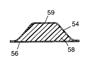
Fig. 4a illustrates a cross-sectional view of an article of the invention
comprising exterior film covering 54 and vibration attçn~l~tin~ material 58, thearticle having a central raised portion with a flat surface 59 and an adhesive layer
56.
Fig. 4b illustrates a cross-sectional view of the article of the invention
comprising exterior film covering 60, vibration attçn~ting material 62, and pressure
sensitive adhesive layer 64.
Fig. 4c illustrates a cross-sectional view of an article of the invention
comprising exterior film covering 66 and vibration ~ttçnll~ting material 70, thearticle having a central raised portion with a flat surface 69, and a pressure sensitive
adhesive layer 68.
-29-
CA 02248828 1998-09-09
wo 97/38237 PCT/US97/05827
Fig. 4d illustrates a cross-sectional view of the article of the invention
colnplisillg exterior film covering 72 vibration ~tten~.~tin~ material 74 and
pressure sensitive adhesive layer 76.
Fig. 4e illustrates a cross-sectior~' view of the article of the invention
co~npli~;"g exterior film covering 78, vibration ztt~n.J~tine material 80 and
pressure sensitive adhesive layer 82.
Fig. 4f illustrates a cross-sectional view of the article of the invention
comprising exterior film covering 84, vibration attt n~l~ting material 86 and
pressure sensitive adhesive layer 89.
Fig. 4g illustrates a cross-sectional view of the article of the invention
co",p,;sing exterior film covering 90 and vibration attçn..~ting material 92 thearticle having a raised curved portion 91 and a raised flat portion 93.
Fig. 4h illustrates a cross-sectional view of an article of the invention
comprising exterior film covering 94 and vibration Attenu~tin~ material 96.
Fig. 4i illustrates a cross-section~l view of an article comprising two articlesof the invention joined together by their exterior film coverings 104 and 100. One
article cor,Lains vibration Attçn.nAtin~ material 106 and the other contains vibration
att~n-l~tin~ material 102. Adhesive layers 103 and 105 is present on the exterior
film covering 104.
Fig. 4j illustrates a cross-sectional view of an article of the invention
comprising exterior film covering 110 (~"~"is;ng film se~mçnts 113 and 115,
vibration ~ttçnu~ting material 112 and pressure sensitive adhesive layer 114
wherein the article has a tri~n~-lAr cross-section.
Fig. 4k illustrates a cross-sectiQn~l view of the article of the invention
co,np,isillg exterior film covering 116 and vibration Atten~tin~ material 118,
wherein the article has a prism shape. The exterior film covering 1 16 extends away
from the vibration ~ttem~tin~ material 118 to form flaps 120.
Fig. 41 illustrates a cross-sectional view of the article of the invention
comprising exterior film covering 122 (comprising film se~;~"~nls 123 and 125) and
vibration attenu~ting material 124, having two projections (126 and 128) e~cten~ing
from the top surface of the article at either side of the top surface.
-30-
CA 02248828 1998-09-09
W097/38237 PCT~US97/05827
Fig. 4m illustrates a cross-sectional view of an article of the invention
CGIl.pli~;ng exterior film covering 130 (comprising film segrnçnts 133 and 135),vibration attçn~ting material 132., having a central projection 136 extPn-iing from
the top surface of the article.
Fig. Sa illustrates a cross-sectional view of an article of the invention
- comprising exterior film covering 138, vibration ~ttçn~ating material 140, and
pressure sensitive adhesive layer 142 coated against the exposed surface of
vibration atten~tine material 140.
Fig. 5b illustrates a cross-sectional view of the article of the invention
comprising exterior film covering 144, vibration ~ttP.n-~ting material 146, and
pressure sensitive adhesive layer 148. The exterior film covering 144 and pressure
sensitive adhesive layer 148 extend to form flaps 150.
Fig. Sc illustrates a cross-sectional view of an article of the invention
col..l,.;sing exterior film covering 152, vibration ~ttçn~ating material 154, and
15 pressure sensitive adhesive layer 156.
Fig. 5d illustrates a cross-sectional view of the article of the invention
co..-p.ising exterior film covering 158, vibration ~ttçn~ting material 160, pres~ur~
sensitive adhesive layer 162, film layer 164, and pressure sensitive adhesive layer
166.
Fig. Se illustrates a cross-sectional view of an article of the invention
comprising exterior film covering 168, vibration ~ttçn-~ting material 170, interior
film divider 172, a di~ren~ vibration ~tten~l~ting material 174, pressure sensitive
adhesive layer 176, and flaps 178.
Fig. 5f illustrates a cross-sectional view of the article of the invention
comprising two separate attenn~tors adhered together, the first comprising exterior
film covering 180, vibration ~ttçnl~tinp~ material 182, and pressure sensitive
adhesive layer 184, and the second comprising vibration ~ttçn~-~ting material 188,
exterior film covering 186, and pressure sensitive adhesive layer 200.
Fig. 5g illustrates a cross-sectional view of the article of the invention
comprising exterior film covering 202, vibration ~tt~n~ting material 204, interior
-31-
. .
CA 02248828 1998-09-09
W 097/38237 PCTAUS97/05827
film divider 206, a di~rerent vibration ~ttçm.~tine material 208, pressure sensitive
adhesive layer 210, and flaps 212.
Fig. Sh illustrates a cross-sectiQn~l view of the article of the invention
co~ ising exterior film covering 214 (made up of film se~ s 216, 217, and
219), vibration attem~qting material 218, pressure sensitive adhesive layer 224, and
flaps 220.
Another embodiment of the article of the invention comprises an exterior
film covering with holes, vibration ~ttçnu~ting material, pressure sensitive adhesive
layer, and flaps.
Another embodiment of tthe article of the invention comprises an exterior
film covering which col"l ,;ses film and film se~ 1 vibration ~ttçml~tinp material,
pressure sensitive adhesive layer, and flaps. The exterior film covering is thus a
single layer in some areas and a double layer in others.
Another embodiment of the article of the invention comprises exterior film
covering comp, ising a film and another film having projections, vibration
çml~ting material, pressure sensitive adhesive layer, and flaps.
Another embodiment ofthe article ofthe invention cGn""ises exterior film
covering co~.~p~;s;ng film seg.\.- .1 and film, vibration ~ttçn..~ting material, adhesive
layer, and hole.
Another embodiment of the article of the invention co",p,ises an exterior
film covering comprising film segn..~nl and pelr~laled film having pelro,~lions,vibration ~tten.l~ting material, and structured pressure sensitive adhesive layer,
having projections and flaps.
Another embodiment of the article of the invention comprises exterior film
covering, vibration attçn.latin~ material, and pressure sensitive adhesive layer.
Fig. 6a illustrates a cross-sectional view of the article of the invention
co""),i~i~,g exterior film covering 282, vibration ~ttçn..~ting material 286, and
pressure sensitive adhesive layer 288. Protrusions 284 extend from the inner
surface of the exterior film covering in a direction towards the interior of the article.
Fig. 6b illustrates a cross-sectional view of an article of invention comprisingexterior film covering 290, vibration attçnU~ting material 294, pressure sensitive
CA 02248828 1998-o9-o9
W O97/38237 PCTAUS97/05827
~ adhesive layer 296, and flaps 298. Protrusions 292 extend from the outer surface of
the exterior film covering 290 in a direction away from the interior of the article.
Fig. 6c illustrates a cross-sectionql view of an atticle of the invention
coln~lis;ng exterior film covering 300, vibration att~n~l~ting material 304, pressure
sensitive adhesive layer 306, and flaps 302.
Fig. 7a illustrates a cross-sectional view of an article of the invention
co,n~ i, g an exterior film covering which is formed from film layers 308, 310, and
312; vibration attçn~l~ting material 314, p~essule sensitive adhesive layer 316, and
flaps 318.
Fig. 7b illustrates a cross-sectional view of the article of the invention
co,~ ;ng exterior film covering 320, vibration ~tt~m~ting material 322, vibration
~ttçn~tine material 326 which is di~e~enl than that of 322, interior film divider 324
having p~ alions 328, pressure sensitive adhesive layer 330, and flaps 332.
Fig. 7c illustrates a cross-sectional view of an article of the invention
comprising vibration ~tten~ting material 334 and another vibration ~ttçnuatine
material 336, a pressure sensitive adhesive layer 338, and flaps 340. An exterior
film covering is present which is in some area a single layer and in other areas a
double layer. The exterior film covering is a single layer where film 348 contarts
vibration ~qttçn~qtin~ material 334. However, the exterior film covering is a double
layer where film layer 348 contacts film seg~.~enl 344 and also where film layer 348
contacts film segmçnt 346. Film segm~nt 342 which divides vibration ~ttçnll~tingmaterial 334 and 336 is considered to be an interior film divider. Thus, one
contimlouC film having film Se~m~nt~ 342, 344, and 346, in some places is
considered to be part of the exterior film covering and in others an interior film
divider. Film 348 is always considered to be a layer of the exterior film covering.
Fig. 8a illustrates a cross-sectional view of the article of the invention
comprising exterior film covering 350, vibration att~n~~~ting material 352, flaps 354
and pressure sensitive adhesive layer 353.
Fig. 8b illustrates a cross-sectional view of the article of the invention
coll")l;sing exterior film covering 360, vibration ~ttçn~ating material 356, a
CA 02248828 1998-09-09
W 097/38237 PCT~US97/05827
chemically di~le.ll vibration ~tten~l~ting material 358, flaps 362, and pressure sensitive adhesive layer 355.
Fig. 8c illustrates a cross-section~l view of two articles of the invention
joined by a layer of adhesive. One article COIIIIJ1;~S exterior film covering 364 and
vibration ~ttçn-J~ting material 366. The other article co~ )lises exterior Im
covering 370 and vibration attçn~ting material 368. The exterior films 364 and
370 are of dilTe,e--l chemical compositions. The vibration ~tt~m.~tin~ materials 366
and 368 are of di~erenl ch~miC~l compositions. The exterior film cover 370 has an
adhesive layer 371 thereon. The flaps are id~.ntified as 372.
Fig. 8d illustrates a cross-sectional view of two articles of the invention
joined together. One article co...~,.ises exterior film covering 382 and vibration
att~nl)?tin~ material 376. The other article co-ll~li3es exterior film covering 378
and vibration attçn~tin~ material 380. The exterior films 382 and 378 are of
dilrere..L Che~ILC~I compositions. The vibration ~tt~.nl.~ting materials 376 and 380
are of di~e- elll chemical compositions. The articles are joined via a multilayer
construction comprising adhesive layers 382 and 386 and inner film layer 384.
Exterior film layer 378 has a layer of adhesive 381 thereon. The flaps are identified
as 374.
Fig. 9a illustrates a cross-sectional view of the article of the invention
comprising exterior film covering 390, vibration ~tt~ml~ting material 394, flaps 392,
and pressure sensitive adhesive layer 396.
Fig. 9b illustrates a cross-sectional view of two articles of the invention
joined together. The first article colll~)lises exterior film covering 398 and vibration
?ttem~ting material 400. The second article co-.lplises exterior film covering 404,
vibration ~ttçn-l~ting material 406, and pressure sensitive adhesive layer 408. The
articles are joined via adhesive 402.
Fig. 9c illustrates a cross-sectional view of two articles of the invention
joined together via their vibration atten~ting materials. The first article comprises
exterior film covering 410 and vibration att~m~ting material 412. The second
article co--.~,lises exterior film covering 416 and vibration ~ttenn~ting material 414.
-34-
.
CA 02248828 1998-09-09
W O 97/38237 PCT~US97/05827
Fig. 9d illustrates a cross-sectional view of the article of the invention
comprising an exterior film covering 418, a vibration atteml~ting material 420, an
interior film divider 422, a di~re,ll vibration ~tt~n-l~tin~ material 424, and apressure sensitive adhesive layer 426.
Fig. 10a illustrates a cross-section~l view of an article ofthe invention
co~ ,l;s;l~g exterior film covering 428, vibration attçml~tin~ material 430, andpressure sensitive adhesive layer 434. The vibration attçn~ in~ material col-~aills
high modnl~lc filler particles 432.
Fig. lOb illustrates a cross-sectional view of an article of the invention
comprising exterior film covering 436, vibration att~m.~ting material 438, and
pressure sensitive adhesive layer 442. The vibration ~tten~l~ting material cGnla;l s
high mf dnlllc filler particles 440.
Fig. 10c illustrates a cross-sçction~l view of an article of the invention
con~plising exterior film covering 446 ,vibration ~tteml~ting material 448, and
pressure sensitive adhesive layer 452. The vibration attçnllating material contains
high modulus filler object 450.
Fig. 11 illustrates a cross-sectional view of the article of the invention
collll~lis;t~g exterior film covering cOllllJl;sil1g film se~ 454, 455, and 459,vibration ~tteml~ting material 456, 458, and 460, and pressure sensitive adhesive
layers 460, 462, and 464, and interior film dividers 470 and 468. The same
contimlQ~ls film functions as part ofthe exterior film covering (se.g,..~.lc 455, 4s4
and 459) and in other areas ofthe article as the interior film divider (se~ç~n~ 470
and 468).
Method of M~kin~p the Article of the Invention
The article of the invention can be prepa~ ed by a number of methods such
that vibration attçnu~ting material is at least partially en~losed by an exterior film
covering. A specific article of the invention can be made, for example, by
providing two layers of a desired film (typically a polymeric film such as a
polyethylene or polyester film) of the same dim~n~ions~ heat sealing the edges of the
films together on three sides to forrn a bag, filling the bag with an uncured vibration
attçnu~ting material, sealing the films along the rem~ining side of the bag, thus
.. . .
CA 02248828 1998-09-09
W 097138237 PCTAUS97/05827
~ enclosing the vibration stt~nufltine material in a "pillow" and optionally curing the
vibration ~sttçnu~sting material by app~ - iate means such as by subjecting the sealed
bag to heat or radiation, for e - , le. An initiator can be added to the vibration
-s-ttçn~-s-ting material prior to cure if desired. The rçe~.lt~nt article can optionally
have an adhesive applied to one or more sides to fs~ilitste application of the article
to a surface.
Another method of making a specific article of the invention, for CA ple,
is by blow molding a film (such as a polymeric film, for example) into a desiredshape, removing the shaped film from the mold, and filling the shaped film with an
uncured vibration attçnllating material. The vibration ~ttçn-l~ting material can be
optionally cured by a number of methods, such as those described above. An
additional film layer(s) and/or film seg~ (s) may optionally be lsminsted over
some or all of the c~.l osed vibration ~s~ttAn~lstinp material. An adhesive layer may
optionally be coated over some or all of the film coating and/or optionally an
adhesive may be coated on some or all of any exposed vibration att~nu~stinp
material.
A layer of adhesive (such as a pressure sensitive adhesive) may be coated on
an outer surface of the exterior film covering of the article and/or on an exposed
surface of vibration stten--stin~ material. Optionally a layer of adhesive may be
coated on at least a portion of an inner surface of the exterior film covering prior to
addition of the vibration ~stt~n~l~ting material. In addition a layer of adhesive may
be coated on at least a portion of one or both surfaces of an interior film divider
which separates one area of vibration att~n--~ting material from another. An interior
divider may be included in the article by, for ~ le, first ~Illling a molded
exterior film covering, filling the molded exterior covering partially with a vibration
attçn-)~tin~ material, inse- ling a layer of a dif~elenl film over the vibration~ttçn-.~ting material which will serve as the interior film divider, adding a layer of a
dil~renl vibration attenll~ting material over the interior film divider, followed by
cure, and optionally a layer of adhesive over the exposed vibration att~m~ating
material. Particulate and other additives may optionally be added to the vibration
attçn-.~ting material prior to enclosing with the exterior film cover although in some
-36-
.. .. . ..
CA 02248828 1998-09-09
W 097/38237 PCTnUS97/05827
~ situations they may be added to the vibration attçm-~tin~ material after it is inserted
into a molded exterior film covering, for example. The vibration ~tt~n.nqtin~
material when only partially enclQsed by the exterior film covering must not be in a
liquid state such that it can flow out of its enclosure. The vibration ~qtten~qti~
material is thus typically a solid or gel which is bonded to the exterior film covering,
typically due to the possible adhesive nature of the vibration ~ttçn..qting material
~Itholl~h this may be due to a separate adhesive which may optionally be used tobond the vibration ~tten~l~qting material to the exterior film covering.
These methods and articles described are not meant to be limiting
Uses of the Articles of the Invention
The articles of the invention can be used for numerous applications.
F. ~ 'es of suitable applications include, for structures selected from the group
con~;sling of disk drive ~c~F.."hliçc, optical disk drives, compact disk acsemhlie
appliql~ces~ transport vehicles, ~1tomobiles, doors, drawers, hoods, comruters,
printed circuit boards, and test eq~irm~nt.
The article of the invention can, for t,~ c, be placed with, on or within a
structure to be ~qttçn~qtecl The article may be adhered to the structure via an
20 adhesive. Alternatively it may be placed or wedged in its place of use without an
adhesive if the structure of the article is conducive to such pl,qcP.ment Other
methods of pl ~,cPm~nt are also possible.
The shape of the article of the invention, selection of polymeric or non-
polymeric films, selection of vibration qttçn~.q~in~ material(s), additives, etc. are all
based on the end use pe,r~"",ance and envhor.. ~ ql requiremenls of the article.
The article of the invention can be as thin or as thick as needed for a given
application.
For most applications the article has a thickness of about 0.025 to 50mm,
preferably about 0.125 to 25mm, and most plefelably about 0.125 to about
1 7.5mm, For most applications the article has a width of about 1.25 to 75mm,
preferably about 2.5mm to 50mm, and most pler~lably about Smm to about
-37
CA 02248828 1998-09-09
WO 97t38237 PCT/US97/05827
~ 37.5mm. For most applicalions the article has a length of about 1.25mm to 75 mm,
prere,2,bly about 2.5 to 50mm, and most prerelably about 1.35 to about 37.5mm.
For most applications the article has an exterior film covering with a
thickness of about 0.005 to 1.25mm, preferably about 0.025 to 0.75mm, and most
ple~-~bly about 0.025 to about 0.375mm.
When present, an interior film divider typically has a thickness of about
0.005 to about 1.25mm, preferably about 0.005 to about 0.075mm, most preferably
about 0.01 to about 0.375mm.
For a typical disk drive applic~lion for dqfnp;~ a voice coil motor between
the top magnet plate and the disk drive cover, the exterior film covering typically
ranges from about 0.0127mm (0.5mil) thickness to about 0.508 to 0.762 (20 to 30
mils) thiclrnçse, pre~,ably about 0.025mm(1 mil) to 0.25mm(10 mils), and most
p~e~l~bly about 0.025mm(1 mil) to about 0.178(7 mils) thic~ness. The vibration
~ttemlating material llL~l~ness is dep~ndent upon the particular application. For a
typical disk drive application, the vibration ~ttçn.-~tine material nominal thicl~nçs~
(~Csllmin~ a basic tn.nç~ted flat top/flat bottom pyramid shape damper) is typically
in the range from about 0.0127 mrn (0.5 mil) lhichRss to about 12.7mm (500 mils)th;~~nf~.~s Most applications typically require a damper design with a damping
material thiclrness of about 0.25mm (10 mil) to about Smm (200 mils).
Preferably the vibration ~ttçnu~ting material has a glass transition
te~ )cl alul e of less than about 60~C at 1 Hz., more pre~- ~bly less than about 45~C
at 1 Hz, and most preferably less than about 38~C at 1 Hz.
The overall geometry of the article of the invention will vary with the degree
of vibration attçnu~tion required for an application. For a typical disk drive, and for
a vibration ~ttem~ting article applied between the top magnet plate of the actuator
motor and the top cover and that is designed to have a trunc~ted (flat top)Mat
bottom pyramid shape, and where the top of the damper is from 50-80% of the
surface area of the bottom of the article, the top of the article will have a top flat
surface area that ranges from about 6.45 square mm (0.1" squared) to 2581 squaremm (2" squared). The damper for this application is also under a degree of
co~llpres~ion, typically ranging from about .5% to 50% after in~t~ tion.
CA 02248828 1998-09-09
W O 97/38237 PCTAUS97/05827
E~amPle
The invention has been described with refe~ ce to various specific and
pre~c~led embodiments and will be further described by rcrelence to the following
det~iled example It is understood, however, that there are many extensions,
variations, and modifications on the basic theme of the present invention beyondthat shown in the e~...rle and det~;led description, which are within the spirit and
scope of the present invention
E~ample 1 - Single Layer Damper:
A 0 10 mm thick amorphous polyester film was set over a heat re~;sl~ l
mold and heated to allow the film to take the shape of the mold The shape of themold was a truncated pyramid measuring 12 mm x 12 mm at the base,
appro~ alely 8 mm x 8 mm at the top, and appl ~-I.ldtely 4 mm thick The shaped
film was removed from the mold and filled with a partially photopol~me. zed
mixture of by weight
41 parts of isooctyl acrylate
59 parts of isbornyl acrylate
0 04 part of 2,2-~innethoxy-2-phenyl acetophçnon~ which was obtained as
Irgacure~65 1 from Ciba Geigy
The partial photopoly.nel.~---g of the mixture was acco...plished in an inert
(nitrogen) atmosphere using a bank of 40-watt fluorescc--~ black lights to provide a
syrup of a viscosity (Brookfield) of about 3000 cps Prior to filling the shaped film,
0.22 part of hexane diol diacrylate and an -~tlition~l 0.12 part of"Irgacure" 651
were added to the partially polylllcli~ed mixture A 0 025 mm thick film of 3M
SCotcl ~mpTM ISD-262 acrylic polymer on a 0 05 mm thick polyester release liner
was l~min~ted to the 12 mm x 12 mm base ofthe truncated pyramid shaped film
with the partially poly.nc ized mixture in intim~te contact with the Scotçhd~mplM
ISD-262 polymer The filled shaped film was irradiated with the same fluorescent
lamps for 10 minutes to complete the pOI~/lllcl izalion of the partially polymerized
-39-
.
CA 02248828 1998-09-09
W 097138237 PCTrUS97/05827
mixture. The polyester release liner was then removed. The res ~lting article was a
single layer ~ttenuatQr ready for testing.
Comparative E~ample I - Current Generation Damper Design
A damper currently available from 3M and used for a disk drive actuator
application is designqted as follows:
Two P~lnt Damper Design:
Part one: Applo~;...~t~ly 4mm thick ISD-110 ~1~."~ material with
0.05mm ISD-112 ds~.~pil-~ material layer ~tta< hed on the base and ap~ xi,l,dlely
1 Smm x 1 Smm length and width die cut rectanEle.
Part two: 28mm x 28mm die cut part of 3M VC-134 polyethylene release
film 0.016 mm with a 0.04 mm thick acrylic pressure sensitive adhesive on one
surface.
The Example 1 and the CGnlpa ~ e Example 1 dal-~;)c- ~ as pr~pd~ed above
were tested in the following configurations:
Configuration 1-The disk drive cover of the designqted test drive was
removed. One of the E~ampl~s 1 dampers was ~ttnehed to the top surface of the
msgnetie plate of the act-l~tQr motor so that the base of the damper was in contact
with the plate. It was attached such that when the cover was re~ttAçh~l1 the
damper would be coll~pl~s~ed by at least 1 percent ofthe d~-pel~ total thietrness
Configuration 2-The same as Configuration 1 except that two Example 1
dampers were ~tt~~hed side by side on the top surface of the mqgnetic plate.
Configuration 3-The same as Configuration 1 except that one Colllpa,dLi~e
Example 1 damper was used in the drive. Part one was ~tt~ched to the top surfaceof the m~netic plate and Part two was ~ttached to the inner surface of the drivecover via its adhesive in a position which allowed its adhesive free side to directly
contact Part one when the cover was re~tt;lch.od
Configuration 4-The disk drive without using any darnper.
The disk drive cover ofthe decign~ted test drive was removed. One or two
Example 1 and Col.-pa- a~i~e Example 1 darnpers were added to the top portion of
-40~
CA 02248828 1998-09-09
W097/38237 PCT~US97/05827
~ the actuator motor on the top magnet plate. The dampers were specifically attached
to the magnet plate of the actuator motor such that when the cover was re~tt~che(l
the darnper would be co",~ ssed by at least 1% ofthe dampers total th~ ness for
all dçci~ The drive was tested at 20-30~C in an ~r ~-ctic chqmber.
The drive was then placed into a test room for acoustic meas~rt;,nenls and
- started. The drive reached the desired ope.alillg spindle speed and a computer
cormected to the disk drive sent instructions to the drive to allow the actuatormotor to do random movements moving the read-write heads quickly over a series
of data or servo tracks. This movement of the actuator created vibrations in theactuator assembly and other areas of the drive, leading to acoustical noise above the
levels when the actu~tQr in the drive is not opelalii~g~ Adding a damper to the
actuator asse.llbly for this test between the cover and actuator reduced this noise.
Monitoring the acoustical levels of the drive was a microphone (placed
appro,.;...~tely 2 feet from the drive) ~ttr~hed to a Bruel and Kj~r frequency
analyzer. The test measured the noise in dBA over a frequency range in Hz. This
tester allowed collection of data for the relative acoustic~l pel roll.lance of the drive
with no actuator dampers and the Example 1 and Co~pal ~live Example 1 dampers.
Results are reported in the table below. Configuration 1 is identified in the table as
"1 x Example Damper" Configuration 2 is id~ntified in the table as "2 x F.Y~nnple
Damper", Configuration 3 is identified in the table as "Co.llpa,ali~e Example
Damper", and Configuration 4 is identified in the table as "No Damper".
-41 -
.
CA 02248828 1998-09-09
W 0 97138237 PCTAUS97/0~827
FREQUENCY Co.. ,l,a,a~ e I x 2 x No
Example Example Example Damper
Damper Damper Damper
200 2.09 13.55 12.28 30.13
250 17.07 20.25 19.43 19.66
315 11.4~ 16.49 17.07 17.50
400 15.90 19.90 16.86 17.92
- 500 23.05 23.40 20.15 21.54
630 26.20 26.20 21.61 24.62
800 24.46 23.54 17.92 22.~3
1000 24.76 28.88 25.87 30.36
1250 29.89 33.30 33.18 40.05
1600 25.47 27.33 26.46 40.43
2000 30.83 30.34 29.37 35.82
2500 32.34 32.95 29.19 28.41
3150 27.47 28.53 27.37 30.29
4000 32.57 37.61 30.88 37.13
5000 31.91 34.10 32.78 30.57
6300 20.39 18.65 18.11 22.18
8000 ~9.66 21.73 18.04 21.99
10000 14.53 15.05 12.51 14.89
12500 13.03 13.95 12.30 13.15
16000 12.35 10.49 9.43 11.90
20000 9.90 6.07 5.53 8.70
The data in the above table shows that the dampers of the invention have
exce~ nt cl~...pi~g pe-~..~ ce as compared to the colll?araL,~e damper example.
Either one or two smaller Example 1 dampers provided nearly the same damping
benefit or improved p~l~.. ance as cGn~pared to the larger colllpal~Li~e damper.So, in addition to the benefits associated with the example dampers design for
environm~nt~l protection, cleanability, one piece design, etc., the example dampers
have excellent damping pel~o~ll,ance.
The foregoing detailed description and examples have been given for clarity
of underst~n-iing only. No llnnecçss~ry limitations are to be understood thelefiolll.
The invention is not limited to the exact details shown and described, for variations
obvious to one skilled in the art will be in~.h~ded within the invention defined by the
claims. Varying damper designs may also provide for better dal"pil-g results than
shown by the above example.
-42-
CA 02248828 1998-09-09
W O 97/38237 PCTnUS97/05827
E~ample 2 - Outgassing Ev~luation
In order to dçmonctrate the improved outg~Ccing pe.ro~ ce ofthe novel
dampers as colll~ared to control d~llpe~ ~ not having an exterior film covering,S sample dal,lpct~ ofthe invention were pl.,palcd and tested for Olltg~CCi~g
pcl~,lll~ce.
Four single layer dampers were prepa~ed as described in Example 1. The
polyester outer film was removed from two of the dampers leaving just the
viccoelsetic d~n ring polymer in the shape of the trunrqted p,vramid in order toprovide the Control Samples. The le ~;n;~g two dampers with their coverings
intact were ide~ntifif~A as the Ex. 1 dampers.
Testing was done by placing the darnpers in separate clean preweighed
qh~mimlnl pans with the base of the damper in contact with the bottom surface ofthe test pan. The dampers were weighed on a scale in the test pans and then placed
into a Class 100 Cleanroom convection oven that had been prehcd~ed to the desired
test tellli)c~ re, 1 50~C. After 2 hours in the oven, the sal~lpl e s were removed from
the oven, placed into a dessicator for 30 minutes to allow to cool and stabilize, and
then reweighed to determine the weight loss of each sample.
The average weight loss of the 2 samples for each condition are showed in
the following table.
SamPles % Wei~ht Loss
Control 0.336
Ex. 1 0.167
The data for the outg~e,eing weight loss shows that
that the samples ofthe invention have improved o~t~eeing p~lrolll~ ce as the %
weight loss is less than the s~mples of the control. The above data shows that the
novel damper design of the invention does provide for an improved olltg~csing
design ae compared to the Control Samples, for example as the part is used for disk
drive applications.
-43 -
.. .. . ~ .. .. . . .
CA 02248828 1998-09-09
WO 97/38237 PCTIUS97/05827
The foregoing detailed description and examples have been given for clarity
of understanding only. No ~.nl~ecess~i y limitations are to be understood therefrom.
The invention is not limited to the exact details shown and described, for variations
obvious to one skilled in the art will be in~luded ~,vithin the invention defined by the
claims. Varying damper designs may also provide for better outg~ing results thanshown by the above example.
-44-