Language selection

Search

Patent 2248845 Summary

Third-party information liability

Some of the information on this Web page has been provided by external sources. The Government of Canada is not responsible for the accuracy, reliability or currency of the information supplied by external sources. Users wishing to rely upon this information should consult directly with the source of the information. Content provided by external sources is not subject to official languages, privacy and accessibility requirements.

Claims and Abstract availability

Any discrepancies in the text and image of the Claims and Abstract are due to differing posting times. Text of the Claims and Abstract are posted:

  • At the time the application is open to public inspection;
  • At the time of issue of the patent (grant).
(12) Patent Application: (11) CA 2248845
(54) English Title: HEATER
(54) French Title: APPAREIL DE CHAUFFAGE
Status: Deemed Abandoned and Beyond the Period of Reinstatement - Pending Response to Notice of Disregarded Communication
Bibliographic Data
(51) International Patent Classification (IPC):
  • H05B 03/18 (2006.01)
  • H05B 03/06 (2006.01)
  • H05B 03/28 (2006.01)
  • H05B 03/36 (2006.01)
(72) Inventors :
  • GATES, WILLIAM GEORGE (United Kingdom)
  • KEEGAN, MARTIN MICHAEL MARK (Ireland)
(73) Owners :
  • LUCENT TECHNOLOGIES INC.
(71) Applicants :
  • LUCENT TECHNOLOGIES INC. (United States of America)
(74) Agent: KIRBY EADES GALE BAKER
(74) Associate agent:
(45) Issued:
(22) Filed Date: 1998-09-29
(41) Open to Public Inspection: 1999-04-21
Examination requested: 1998-09-29
Availability of licence: N/A
Dedicated to the Public: N/A
(25) Language of filing: English

Patent Cooperation Treaty (PCT): No

(30) Application Priority Data:
Application No. Country/Territory Date
97308340.5 (European Patent Office (EPO)) 1997-10-21

Abstracts

English Abstract


A heater is disclosed comprising a foil heating
element 6 embedded in a dielectric sheet 8. A a leaf spring
20 which is curved when relaxed, clamps the embedded element
against a surface 18 to be heated.
The heater can be mounted on an internal surface of
the enclosure. Using a proprietary flexible heating
element, the heater has been run at a flux of 3.9 kW.m2.
The heater is mounted with a flexible dielectric face
directly against an internal surface of the enclosure. No
machining of the enclosure is needed since the flexible
dielectric acts as a thermal gasket.


French Abstract

L'appareil de chauffage présenté comprend une pellicule chauffante 6 intercalée dans une feuille diélectrique 8. Un ressort à lame 20, qui est cintré au repos, serre l'élément intercalé contre une surface 18 à chauffer. L'appareil de chauffage peut être monté sur une surface interne du boîtier. Utilisant un élément chauffant souple spécialisé, on a fait fonctionné l'appareil de chauffage à une densité de puissance de 3,9 kW/m2. Dans l'appareil de chauffage, une face diélectrique souple est montée directement contre une surface interne du boîtier. Aucun usinage du boîtier n'est nécessaire puisque le diélectrique souple sert de joint thermique.

Claims

Note: Claims are shown in the official language in which they were submitted.

-5-
CLAIMS
1. A heater comprising: a foil heating element
embedded in a dielectric sheet; and a leaf spring which is
curved when relaxed for clamping the embedded element
against a surface to be heated.
2. A heater as claimed in claim 1, including a
heat conductive layer against that side of the embedded
element, which in use is remote from the surface to be
heated.
3. A heater as claimed in claim 1 or 2, wherein
the embedded element is in the form of a foil element
laminated between two dielectric layers.
4. A heater as claimed in any preceding claim,
including fastening means including shoulder features which
space ends of the spring from the surface to be heated by a
distance approximately equal to the thickness of the
embedded element and any conductive layer.
5. A heater as claimed in any preceding claim,
wherein the spring is formed with an integral concave
projection to serve as a cable clamp.

Description

Note: Descriptions are shown in the official language in which they were submitted.


CA 0224884~ 1998-09-29
HEATER
This invention relates to heaters.
The background to the invention will be explained in
relation to a particular application. The reader will
appreciate, however, that the invention is not limited to
that application.
Externally mounted enclosures for mobile radio base
stations potentially experience a wide range of ambient
temperatures. If the internal temperature drops below about
OoC the electronics cease to function. The external ambient
temperature can fall to -45~C. At low external ambient
temperatures, the heating which arises naturally from the
electronics is insufficient to keep the internal temperature
sufficiently high. Even at higher temperatures where the
heat dissipation in the electronics is sufficient to keep
the electronics operative, there can be a problem if a power
cut occurs. If the internal temperature falls below that at
which the electronics is operative, it will not restart when
the power returns. A heater is therefore desired. In order
to keep the enclosure desirably small the heater should not
be large.
Against this background, in accordance with the
invention there is provided a heater comprising: a foil
heating element embedded in a dielectric sheet; and a leaf
spring which is curved when relaxed for clamping the
embedded element against a surface to be heated.

CA 0224884~ 1998-09-29
In the particular application described above, the
heater can be mounted on an internal surface of the
enclosure. Using a proprietary flexible heating element, we
have been able to run the heater at a flux of 3.9 kW.m2.
The heater is mounted with a flexible dielectric face
directly against an internal surface of the enclosure. No
machining of the enclosure is needed since the flexible
dielectric acts as a thermal gasket. In other conventional
uses of such a heating element it is bonded to a surface
with double sided self adhesive tape. Such tapes are not
operable at the extremes of temperature to which the
enclosure may be subject.
In order to prevent local hot spots, the heater
preferably includes a heat conductive layer against that
side of the embedded element, which in use is remote from
the surface to be heated. To aid assembly, the heat
conductive layer, which may be sheet aluminium, is bonded to
the element with double sided adhesive tape. Once the
element and heat conductive layer are clamped to the surface
of the enclosure, the fact that the double sided tape is
inoperative at extreme temperatures is irrelevant.
Preferably, the embedded element is in the form of a
conventional foil element laminated between two flexible
dielectric layers.
In order to simplify assembly of the heater on the
surface of the enclosure, it preferably includes fastening
means including shoulder features which space ends of the

~ CA 0224884~ 1998-09-29
spring from the surface to be heated by a distance
approximately equal to the thickness of the embedded element
and any conductive layer.
One embodiment of the invention will now be
described, by way of example, with reference to the
accompanying drawings, in which:
Figure 1 is a side view of a heater embodying the
invention;
Figure 2 is a cross section of a spring, from the
heater of Figure 1, when relaxed;
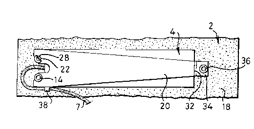
Figure 3 is a plan view of the heater of Figure l;
and
Figure 4 is a detailed cross section of the heating
element of the heater of Figure 1.
Referring to the drawings, an enclosure 2 (only part
of which is shown) contains radio equipment (not shown) for
a mobile telephone base station. The enclosure is formed
from two interfitting light metal castings part of one of
which is shown in Figure 1.
A commercially available trace heating element 4
comprises a Nichrome foil resistor pattern 6, seen only in
section in Figure 4, sandwiched between two layers of
flexible rubber dielectric 8. A thermal cutout 9 is located
inside the heating element 4 and causes a bulge 11 in the
lower layer 8 which projects from the heating element 4.
The element 4 is bonded by a layer of double sided
adhesive tape 10, to an aluminium sheet 12 of similar

CA 0224884~ 1998-09-29
dimensions, which acts to disperse any potential hot spots
in the assembled heater.
Two set screws, screwed into the enclosure, provide
shoulders 16 spaced a distance d from the internal surface
18 of the enclosure 2. A leaf spring 20 is formed with
notches 22 to receive the shanks 24 of the set screws 14 so
as to be retained by the heads 28. The heads are positioned
so that the underside 30 of the spring is spaced from the
surface 18 of the enclosure 2 by a distance approximately
equal to the combined thickness of the heating element and
the sheet 12. The bulge 11 is received by a recess 13 in
the surface 18 thereby locating the heating element 4.
As is shown in Figure 2, the leaf spring 20 is
curved when relaxed. At its end remote from the notches 22,
the leaf spring 20 has a step providing a shoulder 32
leading to a tang 34. The step is approximately the size
as the combined thickness of the heating element 4. When
the tang is fastened to the surface 18 of the enclosure 2 by
a screw 36, the leaf spring clamps the heating element with
a uniform load against the surface 18 of the enclosure 2.
The provision of shoulders 16 and 32 ensure that the spring
is not over tightened on the ends of the heating element 4.

Representative Drawing
A single figure which represents the drawing illustrating the invention.
Administrative Status

2024-08-01:As part of the Next Generation Patents (NGP) transition, the Canadian Patents Database (CPD) now contains a more detailed Event History, which replicates the Event Log of our new back-office solution.

Please note that "Inactive:" events refers to events no longer in use in our new back-office solution.

For a clearer understanding of the status of the application/patent presented on this page, the site Disclaimer , as well as the definitions for Patent , Event History , Maintenance Fee  and Payment History  should be consulted.

Event History

Description Date
Inactive: IPC from MCD 2006-03-12
Application Not Reinstated by Deadline 2001-10-01
Time Limit for Reversal Expired 2001-10-01
Deemed Abandoned - Conditions for Grant Determined Not Compliant 2000-11-27
Deemed Abandoned - Failure to Respond to Maintenance Fee Notice 2000-09-29
Notice of Allowance is Issued 2000-05-26
Letter Sent 2000-05-26
Notice of Allowance is Issued 2000-05-26
Inactive: Approved for allowance (AFA) 2000-05-10
Inactive: Applicant deleted 2000-04-18
Inactive: Correspondence - Formalities 1999-10-29
Inactive: Filing certificate - RFE (English) 1999-10-06
Request for Priority Received 1999-07-13
Letter Sent 1999-06-15
Inactive: Single transfer 1999-05-28
Application Published (Open to Public Inspection) 1999-04-21
Inactive: First IPC assigned 1998-12-02
Inactive: IPC assigned 1998-12-02
Classification Modified 1998-12-02
Inactive: IPC assigned 1998-12-02
Inactive: Courtesy letter - Evidence 1998-11-17
Inactive: Filing certificate - RFE (English) 1998-11-10
Filing Requirements Determined Compliant 1998-11-10
Application Received - Regular National 1998-11-09
Request for Examination Requirements Determined Compliant 1998-09-29
All Requirements for Examination Determined Compliant 1998-09-29

Abandonment History

Abandonment Date Reason Reinstatement Date
2000-11-27
2000-09-29

Fee History

Fee Type Anniversary Year Due Date Paid Date
Registration of a document 1998-09-29
Application fee - standard 1998-09-29
Request for examination - standard 1998-09-29
Owners on Record

Note: Records showing the ownership history in alphabetical order.

Current Owners on Record
LUCENT TECHNOLOGIES INC.
Past Owners on Record
MARTIN MICHAEL MARK KEEGAN
WILLIAM GEORGE GATES
Past Owners that do not appear in the "Owners on Record" listing will appear in other documentation within the application.
Documents

To view selected files, please enter reCAPTCHA code :


To view images, click a link in the Document Description column. To download the documents, select one or more checkboxes in the first column and then click the "Download Selected in PDF format (Zip Archive)" or the "Download Selected as Single PDF" button.

List of published and non-published patent-specific documents on the CPD .

If you have any difficulty accessing content, you can call the Client Service Centre at 1-866-997-1936 or send them an e-mail at CIPO Client Service Centre.


Document
Description 
Date
(yyyy-mm-dd) 
Number of pages   Size of Image (KB) 
Description 1998-09-28 4 141
Claims 1998-09-28 1 26
Drawings 1998-09-28 1 29
Abstract 1998-09-28 1 17
Representative drawing 1999-05-03 1 12
Filing Certificate (English) 1998-11-09 1 163
Courtesy - Certificate of registration (related document(s)) 1999-06-14 1 116
Filing Certificate (English) 1999-10-05 1 164
Commissioner's Notice - Application Found Allowable 2000-05-25 1 163
Reminder of maintenance fee due 2000-05-29 1 109
Courtesy - Abandonment Letter (Maintenance Fee) 2000-10-29 1 184
Courtesy - Abandonment Letter (NOA) 2001-02-04 1 169
Correspondence 1999-07-12 1 33
Correspondence 1999-10-28 1 33
Correspondence 1998-11-16 1 30