Sélection de la langue

Search

Sommaire du brevet 2248845 

Énoncé de désistement de responsabilité concernant l'information provenant de tiers

Une partie des informations de ce site Web a été fournie par des sources externes. Le gouvernement du Canada n'assume aucune responsabilité concernant la précision, l'actualité ou la fiabilité des informations fournies par les sources externes. Les utilisateurs qui désirent employer cette information devraient consulter directement la source des informations. Le contenu fourni par les sources externes n'est pas assujetti aux exigences sur les langues officielles, la protection des renseignements personnels et l'accessibilité.

Disponibilité de l'Abrégé et des Revendications

L'apparition de différences dans le texte et l'image des Revendications et de l'Abrégé dépend du moment auquel le document est publié. Les textes des Revendications et de l'Abrégé sont affichés :

  • lorsque la demande peut être examinée par le public;
  • lorsque le brevet est émis (délivrance).
(12) Demande de brevet: (11) CA 2248845
(54) Titre français: APPAREIL DE CHAUFFAGE
(54) Titre anglais: HEATER
Statut: Réputée abandonnée et au-delà du délai pour le rétablissement - en attente de la réponse à l’avis de communication rejetée
Données bibliographiques
(51) Classification internationale des brevets (CIB):
  • H05B 3/18 (2006.01)
  • H05B 3/06 (2006.01)
  • H05B 3/28 (2006.01)
  • H05B 3/36 (2006.01)
(72) Inventeurs :
  • GATES, WILLIAM GEORGE (Royaume-Uni)
  • KEEGAN, MARTIN MICHAEL MARK (Irlande)
(73) Titulaires :
  • LUCENT TECHNOLOGIES INC.
(71) Demandeurs :
  • LUCENT TECHNOLOGIES INC. (Etats-Unis d'Amérique)
(74) Agent: KIRBY EADES GALE BAKER
(74) Co-agent:
(45) Délivré:
(22) Date de dépôt: 1998-09-29
(41) Mise à la disponibilité du public: 1999-04-21
Requête d'examen: 1998-09-29
Licence disponible: S.O.
Cédé au domaine public: S.O.
(25) Langue des documents déposés: Anglais

Traité de coopération en matière de brevets (PCT): Non

(30) Données de priorité de la demande:
Numéro de la demande Pays / territoire Date
97308340.5 (Office Européen des Brevets (OEB)) 1997-10-21

Abrégés

Abrégé français

L'appareil de chauffage présenté comprend une pellicule chauffante 6 intercalée dans une feuille diélectrique 8. Un ressort à lame 20, qui est cintré au repos, serre l'élément intercalé contre une surface 18 à chauffer. L'appareil de chauffage peut être monté sur une surface interne du boîtier. Utilisant un élément chauffant souple spécialisé, on a fait fonctionné l'appareil de chauffage à une densité de puissance de 3,9 kW/m2. Dans l'appareil de chauffage, une face diélectrique souple est montée directement contre une surface interne du boîtier. Aucun usinage du boîtier n'est nécessaire puisque le diélectrique souple sert de joint thermique.


Abrégé anglais


A heater is disclosed comprising a foil heating
element 6 embedded in a dielectric sheet 8. A a leaf spring
20 which is curved when relaxed, clamps the embedded element
against a surface 18 to be heated.
The heater can be mounted on an internal surface of
the enclosure. Using a proprietary flexible heating
element, the heater has been run at a flux of 3.9 kW.m2.
The heater is mounted with a flexible dielectric face
directly against an internal surface of the enclosure. No
machining of the enclosure is needed since the flexible
dielectric acts as a thermal gasket.

Revendications

Note : Les revendications sont présentées dans la langue officielle dans laquelle elles ont été soumises.


-5-
CLAIMS
1. A heater comprising: a foil heating element
embedded in a dielectric sheet; and a leaf spring which is
curved when relaxed for clamping the embedded element
against a surface to be heated.
2. A heater as claimed in claim 1, including a
heat conductive layer against that side of the embedded
element, which in use is remote from the surface to be
heated.
3. A heater as claimed in claim 1 or 2, wherein
the embedded element is in the form of a foil element
laminated between two dielectric layers.
4. A heater as claimed in any preceding claim,
including fastening means including shoulder features which
space ends of the spring from the surface to be heated by a
distance approximately equal to the thickness of the
embedded element and any conductive layer.
5. A heater as claimed in any preceding claim,
wherein the spring is formed with an integral concave
projection to serve as a cable clamp.

Description

Note : Les descriptions sont présentées dans la langue officielle dans laquelle elles ont été soumises.

CA 0224884~ 1998-09-29
HEATER
This invention relates to heaters.
The background to the invention will be explained in
relation to a particular application. The reader will
appreciate, however, that the invention is not limited to
that application.
Externally mounted enclosures for mobile radio base
stations potentially experience a wide range of ambient
temperatures. If the internal temperature drops below about
OoC the electronics cease to function. The external ambient
temperature can fall to -45~C. At low external ambient
temperatures, the heating which arises naturally from the
electronics is insufficient to keep the internal temperature
sufficiently high. Even at higher temperatures where the
heat dissipation in the electronics is sufficient to keep
the electronics operative, there can be a problem if a power
cut occurs. If the internal temperature falls below that at
which the electronics is operative, it will not restart when
the power returns. A heater is therefore desired. In order
to keep the enclosure desirably small the heater should not
be large.
Against this background, in accordance with the
invention there is provided a heater comprising: a foil
heating element embedded in a dielectric sheet; and a leaf
spring which is curved when relaxed for clamping the
embedded element against a surface to be heated.

CA 0224884~ 1998-09-29
In the particular application described above, the
heater can be mounted on an internal surface of the
enclosure. Using a proprietary flexible heating element, we
have been able to run the heater at a flux of 3.9 kW.m2.
The heater is mounted with a flexible dielectric face
directly against an internal surface of the enclosure. No
machining of the enclosure is needed since the flexible
dielectric acts as a thermal gasket. In other conventional
uses of such a heating element it is bonded to a surface
with double sided self adhesive tape. Such tapes are not
operable at the extremes of temperature to which the
enclosure may be subject.
In order to prevent local hot spots, the heater
preferably includes a heat conductive layer against that
side of the embedded element, which in use is remote from
the surface to be heated. To aid assembly, the heat
conductive layer, which may be sheet aluminium, is bonded to
the element with double sided adhesive tape. Once the
element and heat conductive layer are clamped to the surface
of the enclosure, the fact that the double sided tape is
inoperative at extreme temperatures is irrelevant.
Preferably, the embedded element is in the form of a
conventional foil element laminated between two flexible
dielectric layers.
In order to simplify assembly of the heater on the
surface of the enclosure, it preferably includes fastening
means including shoulder features which space ends of the

~ CA 0224884~ 1998-09-29
spring from the surface to be heated by a distance
approximately equal to the thickness of the embedded element
and any conductive layer.
One embodiment of the invention will now be
described, by way of example, with reference to the
accompanying drawings, in which:
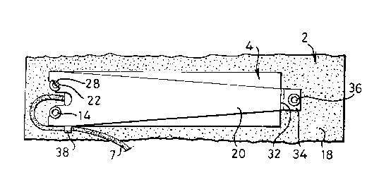
Figure 1 is a side view of a heater embodying the
invention;
Figure 2 is a cross section of a spring, from the
heater of Figure 1, when relaxed;
Figure 3 is a plan view of the heater of Figure l;
and
Figure 4 is a detailed cross section of the heating
element of the heater of Figure 1.
Referring to the drawings, an enclosure 2 (only part
of which is shown) contains radio equipment (not shown) for
a mobile telephone base station. The enclosure is formed
from two interfitting light metal castings part of one of
which is shown in Figure 1.
A commercially available trace heating element 4
comprises a Nichrome foil resistor pattern 6, seen only in
section in Figure 4, sandwiched between two layers of
flexible rubber dielectric 8. A thermal cutout 9 is located
inside the heating element 4 and causes a bulge 11 in the
lower layer 8 which projects from the heating element 4.
The element 4 is bonded by a layer of double sided
adhesive tape 10, to an aluminium sheet 12 of similar

CA 0224884~ 1998-09-29
dimensions, which acts to disperse any potential hot spots
in the assembled heater.
Two set screws, screwed into the enclosure, provide
shoulders 16 spaced a distance d from the internal surface
18 of the enclosure 2. A leaf spring 20 is formed with
notches 22 to receive the shanks 24 of the set screws 14 so
as to be retained by the heads 28. The heads are positioned
so that the underside 30 of the spring is spaced from the
surface 18 of the enclosure 2 by a distance approximately
equal to the combined thickness of the heating element and
the sheet 12. The bulge 11 is received by a recess 13 in
the surface 18 thereby locating the heating element 4.
As is shown in Figure 2, the leaf spring 20 is
curved when relaxed. At its end remote from the notches 22,
the leaf spring 20 has a step providing a shoulder 32
leading to a tang 34. The step is approximately the size
as the combined thickness of the heating element 4. When
the tang is fastened to the surface 18 of the enclosure 2 by
a screw 36, the leaf spring clamps the heating element with
a uniform load against the surface 18 of the enclosure 2.
The provision of shoulders 16 and 32 ensure that the spring
is not over tightened on the ends of the heating element 4.

Dessin représentatif
Une figure unique qui représente un dessin illustrant l'invention.
États administratifs

2024-08-01 : Dans le cadre de la transition vers les Brevets de nouvelle génération (BNG), la base de données sur les brevets canadiens (BDBC) contient désormais un Historique d'événement plus détaillé, qui reproduit le Journal des événements de notre nouvelle solution interne.

Veuillez noter que les événements débutant par « Inactive : » se réfèrent à des événements qui ne sont plus utilisés dans notre nouvelle solution interne.

Pour une meilleure compréhension de l'état de la demande ou brevet qui figure sur cette page, la rubrique Mise en garde , et les descriptions de Brevet , Historique d'événement , Taxes périodiques et Historique des paiements devraient être consultées.

Historique d'événement

Description Date
Inactive : CIB de MCD 2006-03-12
Demande non rétablie avant l'échéance 2001-10-01
Le délai pour l'annulation est expiré 2001-10-01
Réputée abandonnée - les conditions pour l'octroi - jugée non conforme 2000-11-27
Réputée abandonnée - omission de répondre à un avis sur les taxes pour le maintien en état 2000-09-29
Un avis d'acceptation est envoyé 2000-05-26
Lettre envoyée 2000-05-26
Un avis d'acceptation est envoyé 2000-05-26
Inactive : Approuvée aux fins d'acceptation (AFA) 2000-05-10
Inactive : Demandeur supprimé 2000-04-18
Inactive : Correspondance - Formalités 1999-10-29
Inactive : Certificat de dépôt - RE (Anglais) 1999-10-06
Demande de priorité reçue 1999-07-13
Lettre envoyée 1999-06-15
Inactive : Transfert individuel 1999-05-28
Demande publiée (accessible au public) 1999-04-21
Inactive : CIB en 1re position 1998-12-02
Inactive : CIB attribuée 1998-12-02
Symbole de classement modifié 1998-12-02
Inactive : CIB attribuée 1998-12-02
Inactive : Lettre de courtoisie - Preuve 1998-11-17
Inactive : Certificat de dépôt - RE (Anglais) 1998-11-10
Exigences de dépôt - jugé conforme 1998-11-10
Demande reçue - nationale ordinaire 1998-11-09
Exigences pour une requête d'examen - jugée conforme 1998-09-29
Toutes les exigences pour l'examen - jugée conforme 1998-09-29

Historique d'abandonnement

Date d'abandonnement Raison Date de rétablissement
2000-11-27
2000-09-29

Historique des taxes

Type de taxes Anniversaire Échéance Date payée
Enregistrement d'un document 1998-09-29
Taxe pour le dépôt - générale 1998-09-29
Requête d'examen - générale 1998-09-29
Titulaires au dossier

Les titulaires actuels et antérieures au dossier sont affichés en ordre alphabétique.

Titulaires actuels au dossier
LUCENT TECHNOLOGIES INC.
Titulaires antérieures au dossier
MARTIN MICHAEL MARK KEEGAN
WILLIAM GEORGE GATES
Les propriétaires antérieurs qui ne figurent pas dans la liste des « Propriétaires au dossier » apparaîtront dans d'autres documents au dossier.
Documents

Pour visionner les fichiers sélectionnés, entrer le code reCAPTCHA :


Pour visualiser une image, cliquer sur un lien dans la colonne description du document. Pour télécharger l'image (les images), cliquer l'une ou plusieurs cases à cocher dans la première colonne et ensuite cliquer sur le bouton "Télécharger sélection en format PDF (archive Zip)" ou le bouton "Télécharger sélection (en un fichier PDF fusionné)".

Liste des documents de brevet publiés et non publiés sur la BDBC .

Si vous avez des difficultés à accéder au contenu, veuillez communiquer avec le Centre de services à la clientèle au 1-866-997-1936, ou envoyer un courriel au Centre de service à la clientèle de l'OPIC.


Description du
Document 
Date
(aaaa-mm-jj) 
Nombre de pages   Taille de l'image (Ko) 
Description 1998-09-28 4 141
Revendications 1998-09-28 1 26
Dessins 1998-09-28 1 29
Abrégé 1998-09-28 1 17
Dessin représentatif 1999-05-03 1 12
Certificat de dépôt (anglais) 1998-11-09 1 163
Courtoisie - Certificat d'enregistrement (document(s) connexe(s)) 1999-06-14 1 116
Certificat de dépôt (anglais) 1999-10-05 1 164
Avis du commissaire - Demande jugée acceptable 2000-05-25 1 163
Rappel de taxe de maintien due 2000-05-29 1 109
Courtoisie - Lettre d'abandon (taxe de maintien en état) 2000-10-29 1 184
Courtoisie - Lettre d'abandon (AA) 2001-02-04 1 169
Correspondance 1999-07-12 1 33
Correspondance 1999-10-28 1 33
Correspondance 1998-11-16 1 30