Note: Descriptions are shown in the official language in which they were submitted.
CA 02248884 1998-09-14
HELIX ANTENNA WITH INTEGRATED DUPLEXING MEANS AND
CORRESPONDING METHODS OF MANUFACTURE
The field of the invention is that of wide passband antennas with
hemispherical or quasi-hemispherical radiation patterns. More specifically, the
invention relates to resonant helix antennas working in two neighbouring
frequency bands that correspond to tr~nsmission and reception, and especially tothe decoupling of these two channels, and hence to the duplexer function.
The antenna of the invention can find application especially in mobile
satellite con~llullications between users in fixed positions and moving bodies of all
kinds for example, aeronautical, maritime or land-based bodies. In this field,
several satellite communication systems are being implemented or are currently
being developed (these include, for example, the INMARSAT, INMARSAT-M,
GLOBALSTAR, and other systems). These antennas are also valuable in the
deployment of personal communications systems (PCS) using geostationary
satellites.
For all these systems, which provide for links with geostationary satellites,
the very great difference in incidence between the signals received or transmitted
requires that the antenna should have a radiation pattern with hemispherical
coverage. Furthermore, the polarisation has to be circular with a ratio of ellipticity
of more than 5 dB in the useful band.
More generally, the invention can be applied in all systems requiring the use
of a wide band, a radiation pattern with hemispherical coverage, circular
polarisation and a good ratio of ellipticity.
In the above-mentioned fields of application, the antennas must have the
above-mentioned characteristics either in a very wide passband in the range of
lO~o or in two neighbouring sub-bands respectively corresponding to reception
and transmission.
The patent FR-89 14952 filed on behalf of the present Applicant has already
described a known type of antenna well suited to such applications.
This antenna, called a resonant quadrifilar helix (RQH) antenna has
CA 02248884 1998-09-14
characteristics very close to the criteria laid down in a frequency band generally
limited to 5% owing to problems of impedance matching. Operation on two bands
is possible by using dual-layer RQH antennas. These antennas are formed by the
concentric " nesting " of two electromagnetically coupled coaxial resonant
ql~tlrifilar helices.
A q~l~(lrifilar antenna is formed by four radiating strands. An exemplary
embodiment is described in detail in A. Sharaiha and C. Terret, "Analysis of
quadrifilar resonant helical antenna for mobile communications", IEEE -
Proceedings H, Vol. 140, No. 4, August 1993.
In this structure, the radiating strands are imprinted on a thin dielectric
substrate and then wound on a cylindrical medium that is radioelectrically
transparent. The four strands of the helix are open or short-circuited at one end
and electrically connected at the other end with conductive segments positioned on
the base of the lower part of the supporting cylinder. The four strands of the helix
are therefore excited through these conductive segments.
This antenna conventionally requires a supply circuit that excites the
different antenna strands by signals having the same amplitude in phase
quadrature. There are several known techniques used to obtain a supply circuit of
this kind.
In the above-mentioned document "Analysis of quadrifilar resonant helical
antenna for mobile communications", this function is fulfilled by means of a
structure using couplers (3 dB, -90~) and a hybrid ring. This assembly is
implanted on a printed circuit placed at the base of the antenna.
This technique has the advantage of being relatively simple to make and
implement. By contrast, it leads to a non-negligible space requirement as
compared with the antenna (which for example may have a size of about ten
centimetres). This drawback makes this approach incompatible with many
applications, especially when maximum miniatllri.~:~tion is required.
According to a second technique described in J.L. Wong and H.E. King,
"UHF satellite array nulls adjacent signals" (Microwaves & RF, March 1984),
CA 02248884 1998-09-14
each bifilar helix may be supplied by a "folded balun" type of coaxial symmetrizer.
The two bifilars helices are then excited in phase quadrature by means of a hybrid
coupler.
The advantage of this method is that it requires the use of only one external
S hybrid element. By contrast, the symmetrizer/adapter assembly used for this type
of antenna (made for example out of a coaxial section whose core and sheath forma dipole) is complex and bulky.
Furthermore, this type of assembly has the drawback of forming a sort of
passband filter with a band that is still excessively narrow.
A third, more complex technique is described in C.C. Kilgus, "Resonant
quadrifilar helix" (Microwave Journal, December 1970). The coaxial supply line
is split at its end to form a symmetrizer. The phase quadrature is provided by
adjusting the length of the strand.
This technique is used to elimin~te hybrid couplers. However, it has the
drawback of requiring a delicate adjustment of the length of the strand.
Furthermore, the antenna is no longer symmetrical and the structure will be morecomplex. Besides, this method remains specifically reserved for systems using a
narrow working band.
In the case of two-way antennas having to carry out the tr~nsmis.~ion and the
reception of signals, it is naturally necessary, as far as possible, to decouple the
transmission frequency band and the reception frequency band, which are
generally close to each other.
This is the role of the duplexer which is generally placed at the supply point
of the antenna. There are several known types of duplexer. Gord Neilson and
John Mchory, "RF filters and diplexers for cellular applications" (Antem '90)
describes several types of duplexers used in the field of radiocommunications.
In general, these known devices have the drawback of taking the form of an
element that is independent and complementary to the antenna. They therefore
entail considerable space requirements, especially when the antennas are very
small-sized.
CA 02248884 1998-09-14
Furthermore, these are elements that are complicated to make and
implement. Consequently, their cost price is great as compared with the cost of
the antenna itself.
Finally, these duplexers act as filters and may therefore introduce losses of
useful parts of signals.
The invention is aimed in particular at overcoming these different drawbacks
of the prior art.
More specifically, an aim of the invention is to provide an antenna and its
system of supply (hereinafter the term "antenna" includes the antenna proper as
well as its supply system) having two sub-bands that are sufficiently decoupled
not to require the presence of an additional standard duplexer.
In other words, the invention is aimed at providing a two-way antenna that
fulfils the duplexing function in a simple and efficient manner without using
known duplexers.
Another aim of the invention is to provide an antenna of this kind that has a
low cost price and can easily be made on an industrial scale. In particular, theinvention is aimed at providing an antenna of this kind that can be manufactured in
a very small number of successive operations.
Another aim of the invention is to provide an antenna of this kind that does
not require specific and complex setting operations.
Yet another aim of the invention is to provide an antenna of this kind (and
especially the supply system of such an antenna) taking up little space as compared
with known devices.
The invention is also aimed at providing an antenna of this kind that achieves
an equal-amplitude excitation of the four strands and a precise phase quadraturerelationship and hence high quality of circular polarisation in both sub-bands.
These aims as well as others that shall appear hereinafter are achieved
according to the invention by means of a helix antenna with integrated duplexingmeans comprising two decoupled coaxial helices, each formed by r~ ting strands
printed on a substrate, each of said helices being associated with an independent
CA 02248884 1998-09-14
and mini~hlrised structure for the wideband supply of said r~ ting strands, saidsupply structures being printed on said corresponding substrate and comprising at
least one hybrid coupler made out of semi-localised (or "non uniformly spaced")
elements so as to reduce the dimensions thereof.
S The making of the antenna strands and of the supply structure in the form of
printed elements enables the production of the antenna, its supply structure and the
duplexer in one and the same operation without any specific connection means andin a particularly small format.
The use of hybrid couplers made out of semi-localised elements can be used
to obtain the set of desired qualities, and especially to reduce the space requirement
of the assembly as compared with conventionally used lines.
Since the two layers forming each of said coaxial helices are perfectly
decoupled, this structure directly fulfils the role of a duplexer without any
additional element. The supply points of each of the helices respectively and
directly correspond to the tr~n.~mi~ion signal and to the reception signal.
Thus, a very simple low cost two-way antenna is obtained.
Advantageously, said helices, when they are laid out flat, have strands with
directions that are symmetrical to the axis of said antenna and are wound in
opposite directions of winding so that said strands are substantially parallel.
This technique enables the printed face of the internal helix to be pointed
inwards and that of the external helix to be pointed outwards.
Preferably, in order to decrease the decoupling, the points of excitation of
said quadrifilar helices are offset with respect to each other in a plane
perpendicular to the axis of said helices. According to one advantageous
embodiment, they are offset by 135~.
The invention can be applied to all types of helix antennas. According to a
preferred embodiment, said helix is a quadrifilar helix, formed by four radiating
strands supplied by a supply structure comprising three hybrid couplers.
Advantageously, in the last-named case, said supply structure comprises a
first 180~ hybrid coupler associating a supply input and/or output of said antenna
CA 02248884 1998-09-14
with two intermediate outputs and/or inputs phase-shifted by 180~ and two 90~
hybrid couplers each associating one of said intermediate outputs and/or inputs of
said first hybrid coupler with one of the ends of two of said ra~ ting strands.
According to an advantageous embodiment of the invention, said antenna is
S mounted on a support having a first part and a second part that are distinct with
different values of permittivity, said first part bearing said radiating strands and
said second part bearing said supply structure.
Preferably, said first part bearing the antenna strands has a permittivity
greater than 1.
It is thus possible to further reduce the amount of space taken up by the
antenna.
An antenna of this kind as described here above may be used alone or in an
array of antennas.
The invention also relates to the manufacture of said antennas. This
m:lnllfacture is particularly simplified as compared with the prior art techniques.
According to a first method of manufacture of a resonant helix antenna, the
following steps are planned:
- the printing, on a plane substrate, of at least two ra~ ting antennas
designed to form a helix and of an independent, miniaturised
structure for the wideband supply of said radiating strands
comprising at least one hybrid coupler made out of semi-localised
elements so as to reduce the dimensions thereof;
- the winding of said substrate around a cylindrical support.
According to a second method of manufacture of a resonant helix antenna
that is even more simple to implement, the following steps are performed:
- the obtaining of a cylindrical support bearing a substrate;
- the printing, on said substrate, of at least two radiating antennas
designed to form a helix and an independent, mini~tllrised structure
for the wideband supply of said r~ ting strands comprising at
least one hybrid coupler made out of semi-localised elements so as
CA 02248884 1998-09-14
to reduce the dimensions thereof.
Other features and advantages of the invention shall appear from the
following description of a preferred embodiment of the invention given as a simple
and non-restricted example, and from the appended figures wherein:
- Figure 1 exemplifies a quadrifilar helix with integrated supply
according to the invention forming the external layer of the
antenna, laid out in a flat representation;
- Figure 2 shows the helix of Figure 1, wound cylindrically, so as to
form a first operational helix;
- Figure 3 illustrates a second qu:~(lrifil~r helix with integrated supply
according to the invention forming the internal layer of the antenna,
laid out in a flat representation;
- Figure 4 shows the helix of Figure 3 wound cylindrically so as to
form a second operational helix;
- Figure 5 shows a sectional view of the mounted antenna
comprising the helices of Figures 2 and 4, mounted so as to be
offset;
- Figure 6 gives a more detailed view of the supply structure of
Figures 1 and 3;
- Figures 7A to 7C illustrate the design of a -3 dB, 90~ coupler
according to the invention;
- Figure 7A shows a standard coupler with distributed elements;
- Figure 7B shows a corresponding view using p cells;
- Figure 7C shows a corresponding microstrip line coupler;
- Figures 8A and 8B illustrate the design of a -3 dB 180~ coupler;
- Figure 8A shows a 180~ hybrid ring;
- Figure 8B shows a corresponding microstrip line coupler;
- Figure 9 illustrates the standing wave ratio (SWR) of a particular
embodiment of the antenna of Figures 1 and 2;
- Figures 10 and 11 show radiation patterns, measured in right
.
CA 02248884 1998-09-14
circular polarisation and left circular polarisation, of the same
embodiment, respectively at the frequencies 1.98 GHz and 2.2
GHz;
- Figure 12 shows the decoupling (S2l) between the two helices.
The invention therefore relates to an antenna with wideband supply system
with integrated duplexer made according to a simple, low-cost manufacturing
technique.
As indicated here above, the invention can be applied to any type of helix
antenna. The preferred embodiment described here relates to a quadrifilar helix
antenna.
According to the invention, the antenna has two coaxial helices respectively
providing for tr:~n~mi~ion and reception. Each of these helices is formed by four
strands printed on a substrate on which a supply structure is printed conjointly.
Thus, in a single operation, the antenna, supply and duplexer operations are
implanted. This makes it possible to obtain a highly compact antenna with a verylow cost price.
A detailed description shall now be given of the first helix forming the layer.
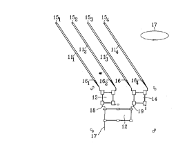
Figure 1 illustrates the printed elements when the helix is laid out flat.
It comprises first of all, four radiating antenna strands 111 to 114.
One mode of determining the characteristics of these strands is given for
example in the patent FR-89 14952 already referred to.
The dimensions of the antenna vary as a function of the frequency band and
the coverage values required. For example, the dimensions of this antenna may beas follows:
- length: 90 mm;
- width: 2 mm;
- thickness: 35 ~m;
- angleofinclination: 54.5~.
They are made for example of copper on a thin dielectric substrate such as
kapton (epsilonr approximately equal to 3.8).
CA 02248884 1998-09-14
The four strands 111 to 114 are preferably open at their upper end 15 1 to
154. They may also be short-circuited. However, the system of the invention is
particularly applopliate to the excitation of antennas with strands that are more
open and, for equal performance characteristics, possess dimensions that are
smaller than those of the short-circuited strand antennas.
The other end 161 to 164 of the strands is connected to the feeder lines of the
supply circuit.
The supply system is made on the same substrate, in the extension of the
antenna. It is formed by three hybrid couplers 12, 13 and 14 designed as semi-
localised elements.
The first hybrid coupler 12 is connected firstly to the input (and output
respectively depending on the use) 17 of the antenna signal and secondly to the
two inputs (and outputs respectively) 18 and 19 of the other two couplers 13 and14. It is a 180~ hybrid coupler.
The hybrid couplers 13 and 14 are two identical 90~ couplers. They are
connected firstly to the input 18 (and 19 respectively) and secondly to the end of
the strands 161 and 162 (and 163 and 164 respectively).
Thus the four strands are supplied in perfect phase quadrature on a
wideband.
The assembly thus obtained is then wound on a support that is cylindrical in
the trigonometric sense. The winding is done towards the exterior (the printed
circuits being on the exterior of the cylinder) to obtain the external helix shown in
a front view in Figure 2.
The cylindrical support is a support that is radioelectrically transparent,
namely it has a permittivity close to l.
It must be noted that it is easy to further reduce the height of the assembly byusing a support with a pellllillivity greater than 1 for the part corresponding to the
antenna strands.
Figure 3 illustrates the elements forming the internal layer of the antenna,
laid out in a flat representation. These elements are quite similar to those described
CA 02248884 1998-09-14
with reference to Figure 1 except that the antenna strands 511 to 514 are inclined in
the opposite direction, the winding direction 52 being opposite the winding
direction 17 of the first helix.
In this example, the dielectric substrate is identical to that of figure 1. The
supply system 53 is also in the extension of the antenna strands 511 and 514 and is
made of semi-localised elements.
The assembly is then wound towards the interior (arrow 52) on a support
that is transparent from the radioelectrical point of view, to give the internal helix
of Figure 4.
The two layers thus obtained are finally mounted concentrically with respect
to one another as is shown in the sectional view of Figure 5.
The external layer (formed by external conductors 61) and the internal layer
(formed by internal conductors 62) are offset by an angle a = 135~ with respect to
their excitation points.
Figure 6 gives a more precise view of the supply structure using semi-
localised elements according to the invention, m~gnified substantially by a factor
of 3 with respect to its real size. It comprises two types of printed lines:
- lines of small width having an inductive characteristic;
- wider lines having a capacitive characteristic.
Thus, the 90~ couplers 13 and 14 are each formed by four wide elements 311
and 314 connected in pairs of two by four lines of small width 321 to 324. The
190~ coupler has six wide elements 331 to 336 connected by six lines of small
width 341 to 346.
Figures 7A and 7C illustrate the design of a -3 dB 90~ coupler.
More substantial details can be found if necessary in the thesis by M.
Coupez, Université de Bretagne Occidentale, "Etude de structures de déphaseurs
potentiellement intégrables à 900 MHz" (Study of phase-shifter structures that can
be potentially integrated at 900 MHz), May 1988.
Figure 7A is the standard drawing of a -3 dB 90~ coupler made of stributed
elements. It has two line sections 81, 82 with a length lg/4 and a characteristic
CA 02248884 1998-09-14
impedance Zc and two line sections 83, 84 with a length lg/4 and a characteristic
impedance Zc/~12.
Each of these two line sections can be replaced by 7~-shaped cells of
localised elements formed by capacitors C and inductors L and L', as illustrated in
Figure 7B.
By using the inductive properties (lines of small width 85) and capacitive
properties (wider lines 86) of the microstrip lines, it is then possible to again
transform the coupler made of distributed elements as shown in Figure 7C.
The same procedure is used to convert the standard structure of a -3 dB,
180~ hybrid ring shown in Figure 8A into a coupler with semi-localised elements
illustrated in Figure 8B.
A helix of this kind especially has the following advantages:
- it has open strands, hence the impedance of each strand can easily
be matched to 50 Q for an antenna having the desired properties
(hemispherical coverage and low reverse polarisation);
- the supply structure using hybrids is a wideband structure that is
perfectly balanced:
- in amplitude (identical for each strand); and
- in phase (0~; :t90~; +180~; _270~);
- the dimensions of the supply device are smaller than those of
known systems (a gain of 50% may be obtained). Indeed, it can
easily be seen that each semi-localised element has a size far
smaller than that of the line that replaces it (which is generally a
size that is a multiple of 1/4);
- the antenna has high strand-to-strand insulation.
By way of an indication, the following are the results of measurements with
a particular embodiment, designed for communications with equipment and
communications at close range.
The dimensions of the assembly formed by the antenna and the integrated
supply are as follows:
CA 02248884 1998-09-14
~i~m~t~r: 26 mm;
- height: 130 mm:
- total weight: 70 g.
The radioelectrical characteristics measured are:
- transmission: 2.17 - 2.2 GHz;
- reception: 1.98 - 2.01 GHz;
- polarisation: rightcircular;
- coverage: 180~;
- ellipticity: < 5 dB for Q < 90~
<2dBforQ<75~;
- defect of omnidirectionality: + 0.6 dB on the horizon.
Figure 9 shows the standing wave ratio (SWR) at the input of each antenna
as a function of the frequency of each of the helices. It can be seen that an SWR
of less than 2 is obtained for each antenna in a 400 MHz band.
Figures 10 and 11 pertain to the radiation patterns measured in right circular
polarisation (a) and in left circular polarisation (b) with a dipole rotating
respectively at the frequencies 1.98 GHz (Figure 10) and 2.2 GHz (Figure 11).
It can be seen that the following are obtained:
- a mean aperture at -3 dB that is quasi-hemispherical and greater
than 180~;
- a rejection of the reversed polarisation greater than -15 dB
throughout the coverage.
Figure 12 shows that the decoupling between the two helices is greater than
20 dB.
An antenna according to the invention can be made in various ways.
Thus, according to a first embodiment, the helices can be printed flat as
shown in Figures 1 and 3. They are then wound on a support to form the antenna
(Figures 2 and 4).
According to another embodiment that is even speedier, the substrate
designed to receive the printed elements may be made directly in its definitive
CA 02248884 1998-09-14
cylindrical shape. In this case, the printing of the strands and of the supply
structure is done directly on the cylinder.
Furthermore, it must be noted that although it can be used as a unit, the
antenna of the invention advantageously lends itself to the making of antenna
arrays.