Note: Descriptions are shown in the official language in which they were submitted.
CA 02248983 1998-09-15
WO 97/34513 PCT/DK97/00117
1
HYDRAULIC LIFTING-LOWERING-SYSTEM FOR A WORKING TABLE, A
COUCH OR LYING FURNITURE OR ANOTHER HEAVY OBJECT.
The invention relates to a hydraulic lifting-
lowering-system for a working table, a couch or lying
furniture or another heavy object, the height level of which
it is frequently desired to adjust or change, and said system
comprising a predetermined amount of hydraulic fluid, a
hydraulic fluid accumulator, the fluid pressure of which on
the hydraulic fluid side is adjustable, a single acting
hydraulic cylinder with two end caps, a piston pressure
chamber and a piston rod which via a piston rod sealing ring
extends sealingly out through the one end cap of the cylin-
der.
Within the fields of chiropractics and physiothera-
py it has lately been recommended to use such systems for
avoiding overloading damages in the neck, the back and the
shoulders, partly by avoiding heavy liftings and partly by
changing the working position frequently and having the
possibility tc change freely between a sitting and standing
position.
From DE-A- 30 21 559 is known such system in
connection with a height adjustable hospital bed for reducing
heavy liftings for the nursing personnel. This known system
has a.o. the disadvantage that hand or foot activated pumping
work should be done by all lifting operations for the bed.
From US-A- 4 037 811 is known a support for an
instrument, whereby an instrument is balanced by a single
acting hydraulic cylinder being connected to a hydraulic
accumulator. One of the disadvantages by this arrangement is
that the cylinder should have an expensive telescopic column
11, 15 of triangular cross section for guiding its rectil-
inear movement, whereby one telescopic part 11 is provided
with a spring loaded pressure shoe 50 pressing the part 15
against the wall sides 52 of the part 11, cf. column 2, line
58 to column 3, line 4, said guiding system provides a
mechanical friction which can be overcome by the gear
transmission 25-28 by rotation of a crank handle.
CONFIRMATION
COPY
CA 02248983 1998-09-15
WO 97/34513 PCT/DK97/00117
2
Said disadvantages can be avoided by a hydraulic
system according to the present invention, which is special
by the combination that the hydraulic cylinder is of the
plunger piston type and that the cylinder wall of the
hydraulic cylinder is slidably and telescopically mounted in
a cylindric guiding tube surrounding the piston rod in its
entire length and being rigidly secured to the one end of the
piston rod via a cross plate or similar construction part.
Thus, beyond that the force of pressure applied at the end of
the hydraulic cylinder at a given accumulator size is only
changing a little over a relatively long stroke length, a
very simple and stable and reliable system without handle is
achieved. It has turned out that e.g. a working table being
supported by such system, the operating pressure of which is
pre-adjusted in accordance with the weight and load of the
working table of e.g. 25 kg, and the stroke length of which
is predetermined according to the desired height regulation
range of the working table of e.g. 400 mm, only required a
force correspcnding to the force of the weight of about 200
g (1,96 N) vertically towards the table plate to change the
height level of the table arbitrarily within the mentioned
400 mm.
This corresponds to a very little pressure change
in the piston pressure chamber, namely 0,8%, such that the
accumulator can be so selected that its operative pressure is
altered 0,8-10% at the most, or even better: 1,0-2,5% at the
most, during the relative stroke of the plunger piston rod
from one to its other operative position of its predetermined
stroke length, which stroke is relative to the hydraulic
cylinder.
Preferably, the end caps of the hydraulic cylinder
are connected via an inner telescopic tube carried tele-
scopically in the cylindric guiding tube serving as an outer
telescopic tube, which together with the plunger piston rod
has been secured coaxially in a mounting block, and the outer
telescopic tube via a slide bushing externally upon the inner
telescopic tube at that end cap, through which the piston rod
20 JUL '98 15:47 PRV 46 8 66CA 02248983 1998 09 15 S.12
PCT/DK97 /00117
29 -05- 1998
3
extends, together with a slide bushing in the outer end of
the outer telescopic tube is adapted to guide the inner
telescopic tube when it is displaced in the outer telescopic
tube. An advantage connected thereto is that even though the
operating pressure is rather high, typically 40-150 bar, a
rugged and stable guiding can be achieved at low friction of
the telescopic construction.
The plunger piston rod advantageously may comprise
a longitudinal bore forming a part of the pressure fluid
connection between the piston pressure chamber and the
hydraulic fluid side of the accumulator.
The hydraulic fluid accumulator may e.g. be of the
kind with a pressure fluid tight membrane separating the
hydraulic fluid from a gaseous fluid serving as pneumatic
spring. This permits the system to obtain very low friction
losses in the accumulator and thus permits low manoeuvering
forces for a user who desires to change said height adjust-
ment. A possible adjustability of the gas pressure permits a
change of the force of the supporting ability of the hydrau-
lic cylinder.
The accumulator may also be of the spring type
whereby a compression spring exerts a force on a piston in an
accumulator cylinder. Thus is achieved an economic embodiment
of the accumulator, and if the spring pressure is adjustable,
a simple adjustment of the hydraulic pressure in the ac-
tivator circuit is obtained by just tightening or slackening
the compression spring.
An embodiment, by which the hydraulic fluid
accumulator is of the spring type, and a compression spring
exerts a force against a piston in an accumulator cylinder,
is characterized in that the wall of the accumulator cylinder
is formed by that part of the plunger cylinder wall which is
situated bqtween a stop ring and one end cap, whereby the
piston is arranged also in the hydraulic cylinder and is
fluid proof sealed and displaceable on the plunger piston rod
between said stop ring on said piston rod and said end cap
into which the piston rod is displaceably arranged.
1MFM SNEET
20/07 '98 LUN 14:40 [TX/RX N 7423]
CA 02248983 1998-09-15
WO 97/34513 PCT/DK97/00117
4
Here the spring is thus fully built-in in the
hydraulic cylinder, whereby a small outer diameter for the
lifting-lowering-unit can be achieved at the expense of the
fact that the spring should be dimensioned with the free
length and spring characteristic demanded for the relevant
and thus economical lifting-lowering-unit.
The hydraulic system according to the invention
will novi be described in more detail in connection with some
embodiments and with reference to the drawing in which:
Fig. 1 shows a hydraulic system where the pressure for the
lifting force of the plunger piston is maintained by a gas
pressure membrane accumuiator, and where the plunger piston
rod is hollow,
Fig. 2 the system shown in Fig. 1 with a compression spring
accumulator instead of the membrane accumulator,
Fig. 3 an embodiment with a compression spring accumulator
integrated in the plunger cylinder, and wherein the plunger
piston rod is solid,
Fig. 4 an embodiment shown in one end position with a
compression spring accumulator, the compression spring of
which is arranged externally for its adjustment from outside
with a handle, and where the plunger piston rod is hollow,
Fig. 5 the embodiment of Fig. 4 in another end position and
likewise in a section along II-II in Fig. 6, and
Fig. 6 a section along I-I in Fig. 5.
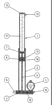
Fig. 1 shows an inner telescopic tube 1, formed as
a cylinder wall 1 in a hydraulic plunger cylinder 1, 6, 7,
10, 11, 12 and 17, said inner telescopic tube 1 being
arranged in an outer telescopic tube 2 which in turn is
secured in a mounting block 3. In said mounting block 3 is
also arranged a pressure accumulator 5 of the membrane type,
which in the embodiment shown is a gas pressure accumulator
which against its membrane has a predetermined but possibly
adjustable nitrogene pressure corresponding to the highest
working pressure in the piston pressure chamber 17 of the
cylinder. The plunger piston rod 6 in the plunger cylinder is
in the embodiment shown provided with a stop ring 7 at its
CA 02248983 1998-09-15
WO 97/34513 PCT/DK97/00117
one end and is at its other end fastened coaxially in the
mounting block 3. On the outer end of the outer telescopic
tube 2 and on the inner end of the inner telescopic tube 1 is
arranged slide bushings 8 so that the outer tube 2 may guide
5 the inner tube 1.
The one end piece or cap 10 of the cylinder 1 with
piston rod washer or sealing 11 and other end piece or cap 12
with bleeder valve 13 is connected via the inner telescopic
tube 1.
On the mounting block 3 is arranged an air filter
14 for permitting the air from the inner of the tube 2 to
escape or to be sucked in during the stroke of the plunger
piston. In the mounting block is furthermore arranged a
filling means 16 for hydraulic fluid under a predetermined
pressure and possibly a quantity regulation valve 15 for
adjustment of the flow rate between the accumulator 5 and the
piston pressure chamber 17.
The plunger cylinder is formed by the inner tube 1,
the plunger piston rod 6, the stop ring 7, the end caps 10
and 12 and the piston pressure chamber 17. The piston
pressure chamber 17 is enclosed by the inner tube 1 and of
the end pieces 10 and 12 and is connected to the accumulator
5 with respect to the flow by a tube system, here formed by
a longitudinal bore 18 in the piston rod 6 and a connection
channel in the mounting block.
The stop ring 7 may also be used as guide ring by
providing it externally with a slide bushing not shown, which
is adapted to slide on the inner wall of the inner tube 1. In
this case the stop ring 7 should be provided with axial flow
openings or the channel 18 should have discharge openings to
both sides of the stop ring 7 so that the pressure fluid is
free to fill the chamber 17.
The working table is ready for use when a load,
e.g. a working table with tools or other equipment, is
supported by the unit shown in Fig. 1 resting on its mounting
block 3 and being under a fluid pressure corresponding to the
vertical load on the unit, where the pressure in the chamber
CA 02248983 1998-09-15
WO 97/34513 PCT/DK97/00117
6
17 against the cross sectional area of the plunger piston
rod, provides the unit with enough force to support the load.
The operator can begin his work, and if the working
height or level of the table should be changed, the table may
with a relatively small manual pulling or pushing force be
moved upwards or downwards to a new working height without
the trouble hitherto being connected to such constructions,
which implied pumping operations, start and stop of elec-
tromotors or manual rotation of crank handles in order to
change the working height of the table.
In Fig. 2 the hydraulic gas pressure accumulator
has been replaced by a compression spring influenced hydrau-
lic piston accumulator 5A which easily by means of an
adjustment screw 20 may have amended the spring pressure of
the compression spring 22A and thus the fluid pressure in the
unit.
From Fig. 3 appears another unit with a hydraulic
piston accumulator, the piston 10C forming an end cap for the
piston pressure chamber 17, said cap being spring loaded by
the accumulator spring 22B. The piston 10C is mounted
slidably and as well sealed by sealings against the plunger
piston rod 6A which is solid, as well as against the inner
telescopic tube 1. This spring 22B of the piston accumulator
is performed with a fixed free length and a certain spring
characteristic which is adapted to the load and the height
position range to which the unit of Fig. 3 should be exposed.
The economy will be good by high piece numbers, but at the
expense of adjustability of the unit.
In Figs. 4-6 is used an accumulator arranged
coaxially to the plunger cylinder in stead of the accumulator
shown in Fig. 2. The spring 22C of said accumulator is so
arranged outside and around the outer tube 2 that the
pressure range can be adjusted by screwing a threaded bushing
23 to tightening or slackening of the spring 22C by means of
a control lever 25. Furthermore, Fig. 4 shows a seeger
circlip 27 for limitation of the setting range or setting
movement, an upper supporting plate 26, a mechanical lock 28,
CA 02248983 1998-09-15
WO 97/34513 PCT/DK97/00117
7
an air bleeding and hydraulic fluid filling means 9A, three
air bleeding holes 29, a stationary 0-ring 30 and a dynamic
sealing 31 in the end cap 10, a sliding sleeve or band 32, a
dynamic sealing 33, a pressure regulating screw 34, an
accumulating chamber 35 and a spring travel chamber 36, the
air bleeding hole of which - along with the other air
bleeding holes 29 - may be provided with an air filter.