Note: Descriptions are shown in the official language in which they were submitted.
CA 02249068 1998-09-29
A STENT INSERTION TOOL FOR USE WITH
A CATHETER SHEATH rNTRODUCER
Suresh Subraya Pai
Karl K. Scheidt
BACKGROUND OF THE rNVENTION
C~theters, cannulas, or catheter sheath introducers, having hemostasis valves which are
mounted on a housing on the end of a tube are well known in the art. An example of a catheter
o sheath introducer is given in commonly assigned U.S. Patent 4,895,565 issued to Hill5te~(1 on
January 23, 1990 which is hereby incorporated herein by reference. These catheters have a distal
end for insertion into the patient and a proximal end which remains external of the patient. Such
catheters are used to facilitate the introduction of other catheters and guidewires into the vascular
system of a patient, while minimizing injury to the patient at the access site. For some
procedures, such as percutaneous transluminal angioplasty, one or more catheters are inserted
into and removed from the patient repeatedly. The presence of the catheter sheath introducer
causes the trauma to the body to be limited to only one catheter entering at the body access site.
All other r~theters and guidewires pass through the catheter introducer, and thus are not
traumatic to the body at the access site.
Catheter sheath introducers typically have a hemostasis valve located within a housing at
the proximal end. The valve can be made from a slit elastomeric partition or membrane. The
valve is designed to seal against leakage of blood, as catheters and guidewires of varying
diameters are passed therethrough.
Recently, procedures such as balloon angioplasty have been followed by an implantation
2s of a stent at the site of the previous angioplasty. Examples of stents and stenting procedures can
be found in U.S. Patents 4,733,665 issued to Palmaz on March 29, 1988 and 5,019,090 issued to
Pinchuck on May 28, 1991, both of which are hereby incorporated herein by reference. Such
stents are usually crimped onto a deflated balloon catheter, inserted through a catheter sheath
introducer and guided to an artery or other vessel. Once at the target site within the vessel the
30 balloon is inflated so as to expand and implant the stent.
. CA 02249068 1998-09-29
Accurate placing of the stent on the balloon is required so that full expansion of the stent
is achi i~. In nddition~ because the stent is typically made from metal and the balloon is made
from polymers, careful hqndling of the device is neceSs~q,ry to prevent the stent from punctiuring
the balloon. It is for these reasons that there has been some difficulty in inserting a balloon
5 c~qthçter, having a stent mounted thereon, through the hemostasis valve of a catheter sheath
introducer. The flaps or slits of the valve may make sufficient contact uith the stent to either
cause the stent to move with respect to the balloon or otherwise damage the balloon or stent
itself. Therefore, there has been a need to provide a device which will ensure safe passage of a
balloon catheter stent combination through the hemostasis valve of a catheter sheath introducer.
o There has also been a desire to provide such a device which can be readily removed from the
catheter sheath introducer and the balloon catheter once the stent crosses the valve so that the
valve can close in order to minimize back bleeding. The present invention fulfills such needs.
SUMMARY OF THE ~NVENTION
In accordance with the present invention there is provided an insertion tool for inserting
medical devices into the human va~culature. Preferably, the tool is designed to be used with a
tubular catheter, such as a catheter sheath introducer, having a lumen of a predetermined
di~qmetçr. Such catheters typically have a distal end for insertion into a v essel, a proximal end for
remqinirlg outside of the vessel, and a longitudinal axis extending therebetween. The pruAinlal
20 end of the catheter typically has a valve attached thereto, which opens to allow passage of medical
devices into the lumen of the catheter so they can then pass into human vessels.The insertion tool is a tubular member made from a material which is preferably more rigid
than the material the catheter tube and valve are made from. The tubular member has a distal end
for insertion into a catheter, a proximal end for remaining outside of the catheter, and a
25 longitu~inql axis extending therebetween. The tool preferably has a substantially smooth inner
surface. The tool further includes a slot extending along its longitudinal axis from its distal end to
its proximal end. In one prefel,ed embodiment, the slot has a predetermined width which is
capable of being manually enlarged.
Also, in accordance with the present invention, there is provided a method for inserting a
30 medical device into a human vessel using the above described insertion tool and catheter. The
CA 02249068 1998-09-29
method first involves inserting a tubular catheter into a vessel. The catheter is preferably a
~thPte~ sheath introducer having a lumen of a predetermined diameter, a distal end for ~. lion
into a vessel, a proximal end for ~ emaining outside of the vessel, a longitudinal axis e~rten.~ing
the. ebetween, and a valve attached to the proximal end which opens to allow passage of medical
devices into the lumen.
The method also includes inserting an insertion tool through the valve of the catheter and
into its lumen. The insertion tool is a rigid tubular member having a distal end for insertion into a
c~theter, a proximal end for remaining outside of the catheter, and a longitudinal axis eYt~nding
thereb~lween. The insertion tool further includes a slot extending along the longitudinal axis from
o the distal end to the proximal end.
The method also includes inserting an interventional catheter, such as a balloon catheter,
into the insertion tool. The interventional catheter has a distal end carrying a medical device, such
as a stent, and a proximal end which extends proximal to the proximal end of the insertion tool.
Thereafter, the method involves removing the insertion tool from the catheter and sliding the
IS interventional catheter through the slot so as to also remove the insertion tool from en~ag~ment
with the interventional catheter.
BR~EF DESCRIPTION OF THE DRAWINGS
While the specification concludes with claims which particularly point out and distinctly
20 claim the subject matter forming the present invention, it is believed that the invention will be
better understood from the following description of the preferred embodiment taken in
conjunction with the accompanying drawings wherein:
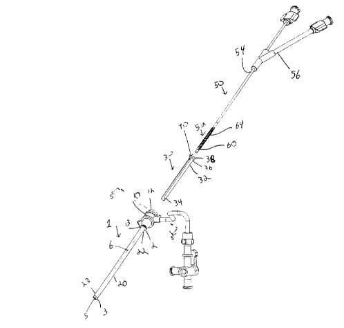
Figure 1 is a perspective view of a catheter introducer, insertion tool and interventional
catheter in accordance with the present invention, wherein the components are shown separately.
2s Figure 2 is a view similar to that of Figure I but showing the interventional catheter and
the medical device inserted within the insertion tool.
Figure 3 is a view similar to that of Figure 2 but showing the insertion tool, along with the
interventional catheter and medical device, inserted within the catheter.
Figure 4 is a view similar to that of Figure 3 but showing how the insertion tool can be
30 removed from engagement with the catheter and interventional catheter.
CA 02249068 1998-09-29
Figure S is a simplified cross-sectional view of proximal end of cath~ter I taken along line
5-5.
Figure 6 is a simplified enlarged view of the catheter 1 and insertion 30 in accordance vith
the present invention.
Figure 7 is similar to that of Figure 6 but showing the insertion tool inserted within the
catheter.
DET~LED DESCRIPTION OF THE rNVENTION
R~fe. l ing to the drawings wherein like numerals indicate the same ele."enls throughout
0 the views, there is shown in Figures I a tubular catheter or catheter sheath introducer 1. C~heter
1 is designed to be inserted into the vessel of a patient and serve as an entrance site for other
catheters, g~idewires or the like. Catheter I includes a proximal end 2, a distal end 3 and a
longit~din~l axis 6 e~tending therebetween. Proximal end 2 has a rigid housing or hub 10
~tt~ched thereto. Housing 10 has a proximal end 12 and a distal end 13. Catheter I also has a
15 flexible tube or cannula 20 extending between proximal end 2 and distal end 3. Tube 20 has a
pro~i".al end 22 and a distal end 23. Preferably distal end 23 of tube 20 has two tapered portions
on the outside diameter (not shown). This design is set forth in U. S. patent 5,417,665 issued to
De La Mata et al., which is hereby incorporated herein by reference. Catheter I further includes a
lumen 5, having a predetermined diameter, extending through the catheter parallel to its
20 longitudin~l axis 6. The housing 10 has an annular valve IS at its proximal end 12 for access to
the lumen 5 of catheter I .
As seen from Figure 5, the housing 10 has an end cap 11, attached to its proximal end, and
annular valve 15. Valve 15 preferably comprises an elastomer having 4-6 slits extending through
the partition at an angle. The elastomer preferably has from about 5 to about 20 percent by
25 weight of a lubricity enhancing additive such as bismuth oxychloride, polytetrafluoroethylene,
titanium dioxide, graphite, polyethylene wax or the like. The end cap can have a compression ring
(not shown) on its interior for causing the partition to bow upwardly which enhances the sealing
ofthe slits. A prel~.ed description ofthe valve is given in U.S. patent 5,453,095 and pending
U.S. patent application Serial No. 08/275,828 "Catheter Hemostasis Valve" filed on July 15,
1994, both of which are hereby incorporated herein by reference.
CA 02249068 1998-09-29
By referring to Figure 6, there is shown an insertion tool 30 made in accordance with the
present invention. Tool 30 includes a tubular member 32, which is preferably made from a
material which is more rigid than what tube 20 and valve 15 are made from. Preferable materials
should be rigid, substantially non-compliant, but still manually pliable. Such materials include
s stainless steel, high density polyethylene, Nitinol, peek and polyamide. Tubular l..e.nbcr 32 has a
distal end 34, a proximal end 36 and a longitudinal axis extending therebetween. Distal end 34 is
designed for insertion into the proximal end 2 of catheter 1 and through valve 15. Proximal end
36 preferably has outwardly flared edge 38. Member 32 preferably has a substantially smooth
inner surface. Tool 30 further includes a slot 40 extending along the longitudinal axis of tubular
o member 32 from distal end 34 to proximal end 36.
Also shown in Figure 1, whose function is described in greater detail below, is an
interventional catheter, shown in the figures as balloon catheter 50. Balloon catheter 50 has a
distal end 52 having an inflatable balloon 60 disposed thereon. Such balloon catheters are
described in U.S. Patent 5,304,197 issued to Pinchuck et al. on April 19, 1994, which is hereby
incorporated herein by reference. Balloon 60 carries a medical device, which is shown as being
stent 64 in the figures. Stent 64 has been crimped onto the balloon 60 in a typical manner which
is well known to those of ordinary skill in the art. Balloon catheter 50 also has a proximal end 54.
Proximal end 54 has what is known to those of ordinary skill in the art as a Y-connector 56
~ttached thereto. As will be appreciated by those skilled in the art a steerable guidewire is
20 typically used in these types of procedures. An example of such a guidewire is given in U.S.
Patent 5,267,574 issued to Viera et al. on December 7, 1993, which is hereby incorporated herein
by reference. Such guidewires are inserted through a lumen in the balloon catheter and help guide
and steer the catheter to the target site.
Many features of insertion tool can best be explained by describing a typical procedure in
25 which it is used. The physician would first insert tubular catheter I into the vessel of the patient,
such as the femoral artery, using any number of means well known to those of ordinary skill in the
art. Proximal end 2 of the catheter and the housing 10 with valve 15 remain outside of the
patient. The valve helps to prevent back bleeding but still allows other catheters and devices to be
passed therethrough and into the vessel.
CA 02249068 1998-09-29
As seen from Figure 2, once the catheter I is in place within the vessel, the physician
would then insert the balloon 60 and stent 64 into the insertion tool 30. Outwardly flared ends 38
help to ensure that the stent enters the insertion tool without snagging or otherwise being caught
up on the proximal end 36. Preferably the entire length of the balloon 60 and stent 64 are
completely inserted within and surrounded by tubular member 32. As seen from the figures, the
proximal end 54 of the balloon catheter 50 is proximal to proximal end 36 of member 32. While
the inner diameter oftubular member 30 is preferably slightly larger than the outside diameter of
the crimped stent on the balloon, tube 30 should be made from a rigid, substantially non-
compliant material, such as stainJess steel, so that when the balloon/stent combination is inserted
lo therein, the ~ meter of the tubular member does not expand anyway. This prevents the valve
from damaging the stent/balloon combination when passing therethrough.
As seen from Figure 3, once the stent and the balloon are placed within the insertion tool,
the insertion tool is then placed within the catheter. That is the physician passes the distal end 34
of tubular ~I.e.~er 30 through the slitted valve 15 of catheter I and into lumen 5 of cannula 20.
s The tubular ,n~.nber is now holding the valve 15 open so that the stent and balloon can be placed
into lumen 50 of cannula 20 while making little to no physical contact with the valve 15. As
mentioned above, this prevents the valve from damaging the stent/balloon combination when
passing therethrough. Once the stent passes completely through the valve, the balloon catheter
can then deliver the stent to the target site within the vessel.
It should be noted that the tool 30 could be inserted into the catheter I prior to the balloon
and stent being inserted into the tool which is the reverse of what is described above. The
sequence of these steps are fully interchangeable within the scope of the present invention.
As seen from Figure 4, once the stent and balloon are passed through the valve, the
insertion tool 30 can be removed from engagement with both catheter I and balloon catheter 50.
25 This is preferable in that removing the insertion tool from catheter 1, allows the valve to close
tightly around the balloon catheter and minimize back bleeding. Removing insertion tool 30 from
engagement with the balloon catheter 50, removes the tool from interfering with the physicians
manipulation of the balloon catheter during the procedure. In order to do this, the physician
would typically first remove tool 30 from catheter I so that distal end 34 of tube 30 is proximal to
proximal end 12 of housing 10. Thereafter, insertion tool 30 is removed from engagement with
CA 02249068 1998-09-29
balloon cathetçr S0 by sliding the catheter through slot 40. If the width of slot 40iS greater than
the ~i~meter of balloon catheter cannula 58, then the balloon catheter should slide out easily. If
not, then the slot could be manually enlarged so as to peel away the tube 30 from the balloon
c~theter.
Another prefe~ I ~d feature of the present invention can best be described by refe., i"g back
to Figure 6. As seen from that figure, insertion tool 30 preferably includes and outwardly
extending bulge or band 39. Band 39 extends along the outer surface ofthe circumference of
tubular ,..e...bel 30 and has a slot 49 which substantially corresponds to 40 on the tool. As seen
from Figure 7, band 39 acts as a stop to prevent over insertion of device 30 within catheter 1.
o The ~ meter of the bulge should be greater than the opening on the catheter which gives access
to the valve. Over insertion could cause unwanted interaction between the distal end 34 of device
30 and tapered interior portion 8, shown in Figure 5, of housing 10. This interaction could cause
either the distal end 34to collapse, or cause damage to the interior of the housing 10.
Although particular embodiments of the present invention have been shown and described,
IS modification may be made to the catheter without departing from the spirit and scope ofthe
present invention. The terms used in describing the invention are used in their desc, iplh~e sense
and not as terms of limitations