Note: Descriptions are shown in the official language in which they were submitted.
~
~ CA 02249191 1999-03-11
- 1 -
Measuring indicator attachment
The invention relates to a measuring indicator attachment with
a pressure transducer, the associated adapter plug and a line
socket connected to it as well as with a casing for receiving
a display.
Such a measuring indicator attachment is known. It can be
implemented, for example, such that no auxiliary energy is
necessary for its operation. In it is provided, for example,
an LCD indicator in a casing connected laterally to an
intermediate piece, which connects the pressure transducer
with the device connector onto which can be screwed a line
socket. This design has a relatively high space requirement
and, in special installation situations, is difficult to read.
It is the task of the present invention to create a measuring
2 0 indicator attachment of the above cited type which is more
compact and yet readily readable.
This task is solved according to the invention for example
thereby that the pressure transducer and the adapter plug with
a line socket are sandwich-like connected on opposing sides
of the casing.
Casing, pressure transducer and device connector with line
socket are therein connected, for example via plug-in and/or
screw connections, so as to be electrically and mechanically
detachable so that in an extremely simple manner the measuring
indicator attachment according to the invention can also be
retroactively installed into existing systems in the case of
all commercially available sensors.
CA 02249191 1999-03-11
- 2 -
The casing can be disposed rotatably about its longitudinal
axis relative to the pressure transducer and, potentially, the
device connector with line socket whereby as an additional
advantage the indicator can always be read from the front
regardless of the position of the pressure transducer.
Simple assembly is possible if the casing can be screwed by
means of central screws onto the device connector of the
pressure transducer.
For this purpose, due to the rotatable support of the device
connector, the casing can be axially rotatable via a grip ring
on the pressure transducer.
The casing can also receive the electronic system associated
with the display.
A further advantage of the invention is attained if the
display is disposed transversely or parallel to the longitudi-
nal axis of the casing since in this case different in-
stallation positions of the display can be realized in
especially simple manner.
In different embodiments of the invention the display can be
implemented as LCD, LED or as an analog indicator.
A front covering, or else a cover, is preferably disposed on
the casing so as to be detachable, whereby a simple cali-
bration of the measuring indicator attachment, for example by
means of zero and and final point setting, can take place via
the buttons disposed on the electronics circuit board.
But in the casing of the measuring indicator attachment
closable openings can also be provided, through which a simple
calibration of the measuring indicator attachment can take
CA 02249191 2005-02-15
27754-30
- 3 -
place, for example by means of zero point and measuring rate
setting.
With the invention is furthermore proposed that the
diameter of the casing, comprising for example synthetic
material and having, for example, the form of a cube, does not
substantially exceed the diameter of the pressure transducer,
i.e.- by no more than 20~, preferably by no more than 10~,
such that high compactness is attained. In particular, the
casing should not be larger than 42 x 42 x 48 mm.
In accordance with a first broad aspect, the
invention provides measuring indicator attachment
comprising: a pressure transducer, a device connector and a
line socket having connected to it, and a casing for
receiving a display, wherein the pressure transducer and the
device connector with the line socket are connected
sandwich-like on opposing sides of the casing, the casing
being connected, rotatably about its longitudinal axis, with
the pressure transducer.
In accordance with a second broad aspect, the
invention provides a measuring indicator device comprising:
a modular pressure transducer; a modular line socket; a
modular casing having a display, a longitudinal axis, a
first end, and a second end opposite said first end and
rotatably connected to said pressure transducer such that
said casing is capable of rotating about said longitudinal
axis with respect to said pressure transducer; and a modular
first connector for connecting said first end of said casing
to said line socket.
Further goals, characteristics, advantages and
possibilities of application of the invention are evident in
the following description as well as the drawings. Therein
all described and/or graphically depicted characteristics by
CA 02249191 2005-02-15
27754-30
- 3a -
themselves or in any meaningful combination from the subject
matter of the present invention, even independently of their
summary.
In the drawing depict:
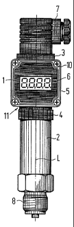
S Fig. 1 a measuring indicator attachment according to the
invention in front view according to one
embodiment of the invention,
Fig. 2 a depiction according to Figure 1 for another
embodiment of the invention,
Fig. 3 a depiction according to Figure 1, however without
pressure transducer and line socket, and
Fig. 4 the measuring indicator attachment according to
Figure 1 in side view.
CA 02249191 1999-03-11
- 4 -
The measuring indicator attachement 1 depicted in the drawings
comprises a pressure transducer 2 with a cylindrical sleeve.
In such pressure transducers the pressure measurement takes
place, for example with the aid of an inner diaphragm wherein
through a piezoresistive sensor element in thin-film technique
the measuring transducing proper takes place. However, the
invention is not limited to measuring transducers of this
specific constructional type. The pressure transducer 2 is
rotatably and detachably disposed on one side of a casing 5
by means of a grip ring 4 formed as a plastic screw nut. At
the end facing away from the casing 5 the pressure transducer
2 bears a screwed-on process connector 8 via which the
connection with a line can be established, whose pressure is
to be monitored.
On the side, diametrically opposite the pressure transducer
2, of casing 5 is disposed a device connector 3 with a line
socket 7. Casing 5 accordingly is disposed sandwich-like
between the pressure transducer 2 and the device connector 3.
By means of detachable plug-in and/or screw connections an
electrical and mechanical connection is established between
the casing 5 and the pressure transducer 2, respectively the
device connector 3 with the socket 7. For example, the device
connector 3 is welded onto the casing 5. The casing 5
comprises for example synthetic material and has the form of
a cube.
On the front side of casing 5 is attached by means of srews
10 a front covering or else a cover 9. In the center of the
front covering 9 is worked in a transparent window below which
is disposed a display 6 with a, for example, 4-digit LED
display. The associated electronics in the form of a circuit
board is also disposed in the casing 5. In the center of the
top side of casing 5 the device connector 3, respectively a
pin plate, is welded on with the aid of ultrasound, on which
. CA 02249191 1999-03-11
- 5 -
the line socket 7, preferably a tessellated connector, is
mounted by means of a central screw.
However, the bottom of casing 5 can be formed such that it
comprises a collar extension 11 wherein is disposed the inner
portion of the line socket 7 which is affixed in the casing
5 by adhesion with reinforcement ribs. Due to the device
connector 3 welded onto the top side as well as a collar
extension 11 disposed on the bottom side with the inner
portion of the line socket 7 the entire casing 5 forms a type
of device connector according to DIN 43650, which can be
screwed onto the pressure transducer 2, however, which
additionally comprises an integrated display 6 and an
adjustable limit contact. The rotatable support of the device
connector 3, respectively of the grip ring 4, on the pressure
transducer 2 permits rotating the housing 5 about its
longitudinal axis L and thus also about the longitudinal axes
of pressure transducer 2, device connector 3 and line socket
7. Consequently, swivelling the display 6 into any desired
reading position is possible.
The described connections are implemented so as to be splash-
proof such that all required degrees of protection can be
attained. Mounting the described embodiment on a pressure
transducer 2 can take place without having to open the casing
5.
In another embodiment of the invention slit-form openings are
disposed in the bottom of casing 5 for leading through the
pins of the device connector for the pressure transducer 2 as
well as a bore for the central screw. Casing 5 in this case
is screwed together with the device connector of the pressure
transducer 2, with connection terminals being placed onto the
pins. The lower casing portion in this embodiment represents
. CA 02249191 1999-03-11
_ ( _
a line socket and the connection on the cover represents a
device connector.
Casing 5 is preferably produced of synthetic material
injection moulding with the front covering or else the cover,
9 being screwed on splash-proof via four screws 10 and a seal.
For setting the measuring range and the limit contact, the
front covering, or else the cover, 9 must be unscrewed and
using the buttons on the electronics circuit board underneath
it, the setting of zero and end point as well as the display
delay must be carried out. Furthermore, in the case of the
limit contact setting, the setting of switching point,
switching direction and switching delay is possible.
Due to the rotatable support of the device connector via the
grip ring 4 on the pressure transducer 2, casing 5 is axially
rotatable so that the swivellability of the indicator is
realized in a simple way.
Figure 2 shows an arrangement according to the invention in
which, in contrast to that shown in Figure 1, the display 6
is disposed parallel to the longitudinal axis L. This permits
taking into account different installation positions of the
measuring indicator attachment 1 without disadvantages being
encountered in the readability of the indicator.
The measuring indicator attachment due to the use of an
auxiliary energy-free display is preferably operatable without
auxiliary energy. Basically, as display 6 are usable LCD, LED
or also analog indicator elements, such as for example
needles.
CA 02249191 2005-02-15
27754-30
_ 7 _
List of Reference Symbols
1 Measuring indicator attachment
2 Pressure transducer
3 Device connector (welded on)
4 Grip ring (plastic screw nut)
5 Casing
6 Display (LED indicator)
7 Line socket (according to DIN 43650)
8 Processor connector (G 1/2 A)
9 Front covering
10 Screws
11 Collar extension
L Longitudinal axis