Note: Descriptions are shown in the official language in which they were submitted.
CA 02249324 1998-09-18
WO 97/43468 PCTJUS97/07112
POLYMER1C STRANDS WTTH HIGH SURFACE AREA AND METHODS FOR MAKING SAME
Technical Field
This invention relates to polymeric strands made by melt-extruding an emulsion
comprising a melt-extrudable polymer as a continuous phase and an immiscible
component
as a discontinuous phase for altering the physical properties of the strand.
Background of the Invention
The melt-extrusion of liquids, such as, for example, thermoplastic polymers,
to form
fibers and nonwoven webs generally involves forcing a molten polymer through a
plurality of
orifices to form a plurality of molten threadlines, contacting the molten
threadlines with a
fluid, usually air, directed so as to form strands (filaments or fibers) and
attenuate them.
The attenuated strands then are randomly deposited on a surface to form a
nonwoven web.
The more common and well known processes utilized for the preparation of
nonwoven webs are meltblowing, coforming, and spunbonding.
Meltblowing references include, by way of example, U.S. Patent Nos. 3,016,599
to
Pent', Jr., 3,704,198 to Prentice, 3,755,527 to Keller et al., 3,849,241 to
Butin et al.,
3,978,185 to Butin et al., and 4,663,220 to Wisneski et al. See, also, V. A.
Wente,
"Superfine Thermoplastic Fibers", Industrial and Engineering Chemistry, Vol.
48, No. 8, pp.
1342-1346 (1956); V. A. Wente et al., "Manufacture of Superfine Organic
Fibers", Navy
Research Laboratory, Washington, D.C., NRL Report 4364 (111437), dated May 25,
1954,
United States Department of Commerce, Office of Technical Services; and Robert
R. Butin
and Dwight T. Lohkamp, "Melt Blowing - A One-Step Web Process for New Nonwoven
Products", Journal of the Technical Association of the PUIp and Paper
Industry, Vol. 56,
No.4, pp. 74-77 (1973).
Coforming references (i.e., references disclosing a meltblowing process in
which
fibers or particles are commingled with the meltblown fibers as they are
formed) include U.S.
Patent Nos. 4,100,324 to Anderson et al. and 4,118,531 to Hauser.
Finally, spunbonding references include, among others, U.S. Patent Nos.
3,341,394
to Kinney, 3,655,862 to Dorschner et al., 3,692,618 to Dorschner et al.,
3,705,068 to Dobo
et al., 3,802,817 to Matsuki et al., 3,853,651 to Porte, 4,064,605 to Akiyama
et al.,
4,091,140 to Harmon, 4,100,319 to Schwartz, 4,340,563 to Appei and Morman,
4,405,297
to Appel and Morman, 4,434,204 to Hartman et al., 4,627,811 to Greiser and
Wagner, and
4,644,045 to Fowells.
Nonwoven webs have many uses including cleaning products such as towels and
industrial wipes, personal care items such as incontinence products, infant
care products,
and absorbent feminine care products, and garments such as medical apparel.
These
CA 02249324 1998-09-18
WO 97/43468 PCT/ITS97/07112
applications require polymeric strands with a wide variety of physical
properties. The
physical properties of melt-extruded polymeric strands are limited, however,
and must often
be engineered or surface treated for use in certain applications. For example,
many
thermoplastic materials used to make polymeric strands and nonwoven materials
are
hydrophobic and do not attract or wick water very well. To make some
thermoplastic
strands and resulting nonwoven materials hydrophilic, they must be treated
with a material
such as a surfactant which is often applied by spraying or dipping the
product. Although
there are many suitable methods and treatments to affect the physical
properties of
melt-extruded polymeric strands and nonwoven materials made therewith, there
remains a
need for a wider variety of physical properties and more economical and
effective ways of
altering the physical properties of melt-extruded strands and nonwovens.
Summary of the Invention
This invention addresses some of the needs described above by providing a
melt-extruded polymeric strand comprising a melt-extrudable polymer and having
a plurality
of fissures in the surface of the strand. Desirably, the strand has a B.E.T.
surface area
within a range from about 0.10 to about 0.18 mzg. This invention also
encompasses a
method for making such a strand by extruding an emulsion while applying
ultrasonic energy
to form the emulsion. This invention further encompasses a nonwoven web and a
method
for making a nonwoven web comprising such a melt-extruded polymeric strand.
More particularly, the melt-extruded polymeric strand of this invention having
the
plurality of surface fissures also has a mean diameter within the range from
about 1 to about
200 micrometers and the fissures are desirably present in an amount from about
1 x10⁸ to
about 1x10'° per m2. The B.E.T. surface area of such a strand is 2 to 6
times the B.E.T.
surface are of an otherwise identical strand lacking the plurality of
fissures. Such a high
surface polymeric strand more effectively wicks liquid such as water than an
otherwise
identical strand lacking the plurality of fissures. The same is true of a
nonwoven web made
with a strand of this invention having the enhanced surface area.
According to an embodiment of this invention, the melt-extruded polymeric
strand
having the plurality of surface fissures may also include an immiscible
component which is
present at the surface of the strand at the fissures. The immiscible component
is immiscible
with the melt-extrudable polymer when the melt-extrudable polymer and the
immiscible
component are at a temperature suitable for melt-extrusion of the polymer. The
immiscible
component desirably performs a function at the surface of the strand not
performed by the
melt-extrudable polymer. For example, the immiscible component can comprise a
hydrophilic polymer while the melt-extrudable polymer is hydrophobic. Other
exemplary
immiscible components include surfactants, odorants and starches.
The polymeric strand of this invention having the plurality of fissures in the
strand
surface is made by applying ultrasonic energy to a portion of a multicomponent
liquid to form
an emulsion and extruding the emulsion. More particularly, the method includes
extruding a
multi-component pressurized liquid through a die assembly, applying ultrasonic
energy to a
2
CA 02249324 1998-09-18
WO 97/43468 PCT/US97107112
portion of the multi-component liquid, and attenuating the extruded multi-
component liquid to
form a strand. The die assembly includes a die housing and a device for
applying ultrasonic
energy to the multi-component liquid. The die housing comprises a chamber
adapted to
receive the pressurized multi-component liquid, an inlet adapted to supply the
chamber with
the pressurized multi-component liquid, and an exit orifice defined by the
walls of a die tip.
The exit orifice is adapted to receive the pressurized multi-component liquid
from the
chamber and pass the multi-component liquid out of the die housing.
The multi-component pressurized liquid comprises a melt-extrudable polymer and
an
immiscible component which is immiscible in the melt-extrudable polymer when
the
multi-component pressurized liquid is at a temperature suitable for melt-
extrusion and is
capable of forming an expanding gas after the multi-component pressurized
liquid is passed
out of the die housing through the exit orifice. The ultrasonic energy is
applied to a portion
of the pressurized multi-component liquid within the chamber and without
applying ultrasonic
energy to the die tip, while the exit orifice receives the pressurized multi-
component liquid
from the die housing chamber. Consequently, the pressurized multi-component
liquid
passes out of the exit orifice in the die tip as an emulsion. The melt-
extrudable polymer
forms a continuous phase of the emulsion and the immiscible component forms a
disperse
phase of the emulsion. Upon extrusion of the multi-component liquid out of the
exit orifice in
the die tip and during attenuation of the extruded multi-component liquid to
form a strand,
the immiscible component forms an expanding gas which explodes through the
surface of
the strand and forms the plurality of fissures in the strand surface.
Desirably, the immiscible component includes water which forms steam during
extrusion of the polymer and explodes through the surface of the strand to
form the fissures.
The immiscible component may also include a functional ingredient such as a
hydrophilic
polymer, a surfactant, an odorant, or the like, as described above with regard
to the
melt-extruded polymeric strand.
According to another aspect, this invention further comprehends a melt-
extruded
polymeric strand comprising a continuous phase which is the melt-extrudable
polymer and a
disperse phase comprising an amendment for altering the physical properties of
the strand.
The amendment is immiscible with the continuous phase when the continuous
phase and
the disperse phase are at a temperature suitable for melt-extrusion of the
polymeric strand.
Described more particularly, the melt-extruded polymeric strand of this
invention
described immediately hereinbefore has a dispersed phase which comprises
discreet
pockets of material separated by the continuous phase. The disperse phase
desirably
includes an ingredient which performs a function not performed by the melt-
extrudable
polymer. For example, the disperse phase may include lubricating oils, skin
emollients,
tinting oils, waxes, polishing oils, silicones, vegetable oils, glycerines,
lanolin, flame
retardants, tackifiers, degradation triggers, insecticides, fungicides,
bactericides, viricides,
colloids, and suspensions. Alternatively, the disperse phase can comprise a
gas such as
air, or an electroluminescent gas such as neon or argon. According to another
embodiment,
the disperse phase can comprise a low melting point metal or alloy such as
bismuth alloys,
3
CA 02249324 1998-09-18
WO 97/43468 PCT/LTS97/07112
indium alloys, tin, or gallium. Such metals should be molten at temperatures
suitable for
melt-extrusion of the polymeric strand. The foregoing amendments which form
the disperse
phase of the polymeric strand impart a variety of physical properties to the
polymeric strand
and allow the polymeric strands to be useful for a variety of end uses.
This invention encompasses a method for making a polymeric strand including
the
amendments described immediately hereinbefore. The method is very similar to
the method
described hereinabove with regard to the strand having the plurality of
fissures except that
the immiscible component of the multi-component liquid does not necessarily
include a
component for forming an expanding gas.
Nonwoven webs made with the above-described polymeric strands are made by
depositing the polymeric strands onto a collecting surface such as in
meltblowing,
coforming, or spunbonding techniques.
Other objects and the broad scope of the applicability of this invention will
become
apparent to those of skill in the art from the details given hereinafter.
However, it should be
understood that the detailed description of the preferred embodiments of the
invention is
given only by way of illustration because various changes and modifications
well within the
scope of the invention should become apparent to those of skill in the art in
view of the
following detailed description.
Brief Description of Drawings
FIG. 7 is a cross-sectional elevation view of an apparatus for making an
embodiment
of the present invention.
FIG. 2 is a photomicrograph of a strand made according to an embodiment of
this
invention with fissures in the surface of the strand.
FIG. 3 is a photomicrograph of another strand made according to an embodiment
of
this invention with a plurality of fissures in the surface of the strand.
FIG. 4 is a photomicrograph of an undrawn strand made according to an
embodiment of this invention. The strand has been insulted on the left side
with tap water.
FIG. 5 is a photomicrograph showing the severed end of a slightly drawn strand
made according to an embodiment of this invention and having a plurality of
fissures on its
surface. The strand has been insulted on the right end with tap water.
FIG. 6 is a photomicrograph of an air drawn strand made according to an
embodiment of this invention with the insult water wicking left to right.
Detailed Description of Embodiments of the invention
As summarized above, this invention encompasses melt-extruded polymeric
strands
with altered physical properties, nonwoven webs made with such strands and
methods for
making the foregoing. After defining certain terms used herein, an apparatus
for use in
making strands in accordance with an embodiment of this invention is
described, followed by
a description of methods for using the apparatus and particular examples of
polymeric
strands made with the apparatus.
4
CA 02249324 1998-09-18
WO 97/43468 PCT/US97/07112
As used herein, the term "strand" refers to an elongated extrudate formed by
passing a polymer through a forming orifrce such as a die. Strands include
fibers, which are
discontinuous strands having a definite length, and filaments, which are
continuous strands
of material.
As used herein, the term "nonwoven web" means a web of material which has been
formed without use of weaving processes which produce a structure of
individual strands
which are interwoven in an identifiable repeating manner. Nonwoven webs may be
formed
by a variety of processes such as meltblowing processes, spunbonding
processes, film
aperturing processes, coforming processes, and staple fiber carding processes.
As used herein, the term "liquid" refers to an amorphous (noncrystalline) form
of
matter intermediate between gases and solids, in which the molecules are much
more
highly concentrated than in gases, but much less concentrated than in solids.
A liquid may
have a single component or may be made of multiple components. The components
may
be other liquids, solids and/or gases. For example, characteristic of liquids
is their ability to
flow as a result of an applied force. Liquids that flow immediately upon
application of force
and for which the rate of flow is directly proportional to the force applied
are generally
referred to as Newtonian liquids. Some liquids have abnormal flow response
when force is
applied and exhibit non-Newtonian flow properties.
As used herein, the terms "thermoplastic polymer" and "thermoplastic material"
refer
to a high polymer that softens when exposed to heat and returns to its
original condition
when cooled to room temperature. The terms are meant to include any
thermoplastic
polymer which is capable of being melt-extruded. The term also is meant to
include blends
of two or more polymers and alternating, random, and block copolymers.
Examples of
thermoplastic polymers include, by way of illustration only, end-capped
polyacetals, such as
poly(oxymethylene) or polyformaldehyde, poly(trichloroacetaldehyde),
polyL-valeraldehyde), poly(acetaldehyde), poly(propionaldehyde), and the like;
acrylic
polymers, such as polyacrylamide, poly(acrylic acid), poly(methacrylic acid),
poly(ethyl
acrylate), poly(methyl methacrylate), and the like; fluorocarbon polymers,
such as
poly(tetrafluoroethylene), perfluorinated ethylene-propylene copolymers,
ethylene-tetrafluoroethyiene copolymers, poly(chlorotrifluoroethylene),
ethylene-chlorotrifluoroethylene copolymers, poly(vinylidene fluoride},
poly(vinyl fluoride),
and the like; polyamides, such as poly(6-aminocaproic acid) or poly( -
caprolactam),
poly(hexamethylene adipamide), poly(hexamethyiene sebacamide),
poly(11-aminoundecanoic acid), and the like; polyaramides, such as
poly(imino-1,3-phenyleneiminoisophthaloyl) or poly(m-phenylene
isophthalamide), and the
like; parylenes, such as poly-p-xylylene, poly(chloro-p-xylylene), and the
like; polyaryl ethers,
such as poly(oxy-2,6-dimethyl-1,4-phenylene) or poly(g-phenylene oxide), and
the like;
polyaryl sulfones, such as
poly(oxy-1,4-phenylenesulfonyl-1,4-phenyieneoxy-1,4-phenylene-isopropylidene-
1,4-phenyl
ene}, poly(sulfonyl-1,4-phenyleneoxy-1,4-phenylenesulfonyl-4,4'-biphenylene),
and the like;
CA 02249324 2004-04-27
pofycarbonates, such as poly(bisphenol A) or
poly(carbonyldioxy-1,4-phenyieneisopropylidene-1,4-phenylene), and the like;
polyesters.
such as polyethylene terephthalate), poly(tetramethylene terephthalate),
poly(cyciohexylene-1,4-dimethylene terephthalate) or
poly(oxymethylene-1,4-cyciohexylenemethyleneoxyterephthaloyl), and the like;
polyaryl
sulfides, such as poiy(p-phenylene sulfide) or poly(thio-1,4-phenylene), and
the tike;
polyimides, such as poly(pyromeilitimido-1,4-phenylene), and the like;
polyolefins, such as
polyethylene, polypropylene, poly(1-butane), poly(2-butane), poly(1-pentane),
poly(2-pentane), poly(3-methyl-1-pentane), poly(4-methyl-1-pentane),
1,2-poly-1,3-butadiene, 1,4~poly-1,3-butadiene, polyisoprene, polychloroprene,
polyacrylonitrile, polyvinyl acetate), poly(vinylidene chloride), polystyrene,
and the like;
copolymers of the foregoing, such as acrylonitrile-butadiene-styrene (ABS)
copolymers, and
the like; and the like.
By way of example, the thermoplastic polymer may be a poiyolefln, examples of
which are listed above. As a further example, the thermoplastic polymer may be
a polyolefin
which contains only hydrogen and carbon atoms and which is prepared by the
addition
polymerization of one or more unsaturated monomers. Examples of such polyolef
ns
include, among others, polyethylene, polypropylene, poly(1-butane), poly(2-
butane},
poly(1-pentane), poly(2-pentane), poly(3-methyl-1-pentane), poly(4-methyl-1-
pentane),
1,2-poly-1,3-butadiene, 1,4-poly-1,3-butadiene, polyisoprene, polystyrene, and
the like, as
wetl as blends of two or more such polyolefins and alternating, random, and
block
copolymers prepared from two or more different unsaturated monomers.
As used herein, the term "hydrophilic", when describing polymers, means a
polymer
having a surface energy at 20°C within the range of about 55 to about
75 dyneslem2. In
addition, as used herein, the term "hydrophobic" with regard to polymers,
means a polymer
having a surface energy at 20°C within the range of about 20 dyneslcm2
to about 50
dyneslcm~
As used herein, the term "emulsion" refers to a relatively stable mixture of
two or
more immiscible liquids that, in some cases, may be held in suspension by
small
percentages of substances called emulsfiers or stabilizers. Emulsions may also
be held in
suspension or stabilized by the continuous phase being extremely viscous, or
by the
solidification of the continuous phase after the fomlation of the emulsion.
Emulsions are
composed of a continuous phase and a disperse phase. For example, in an oil in
water
emulsion, water is the continuous phase and oil is the disperse phase.
As used herein, the term "node" means the point on the longitudinal excitation
axis of
the ultrasonic horn at which no longitudinal motion of the horn ocxurs upon
excitation by
ultrasonic energy. The node sometimes is referred to in the art, as well as in
this
specification, as the nodal point.
The term "close proximity" is used herein in a qualitative sense only. That
is, the
term is used to mean that the means for applying ultrasonic energy is
sufficiently close to
the exit orifice (e.g., extrusion orifice) to apply the ultrasonic energy
primarily to the liquid
6
CA 02249324 2004-04-27
(e.g., multi-component liquid) passing into the exit orifice (e.g., extrusion
orifice). The term
is not used in the sense of defining specific distances from the extnrsion
orifice.
Generally speaking, the apparatus of the present invention includes a die
housing
and a means for applying ultrasonic energy to a portion of a pressurized multi-
component
liquid such as a molten thermoplastic polymer and water. The die housing
defines a
chamber adapted to receive the pressurized multi-component liquid, an inlet
(e.g., inlet
orifice) adapted to supply the chamber with the pressurized multi-component
liquid, and an
exit orifce (e.g., extrusion orifice) adapted to receive the pressurized
liquid from the
chamber and pass the iiquid out of the exit orifice of the die housing so that
the
multi-component liquid is emulsified. The means for applying ultrasonic energy
is located
within the chamber. For example, the means for applying ultrasonic energy can
be tocated
partially within the chamber or the means for applying ultrasonic energy can
be located
entirely within the chamber.
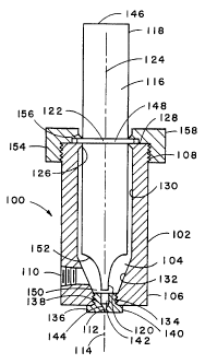
Referring now to FiG. 1, there is shown, not necessarily to scale, an
exemplary
apparatus for emulsifying a pressurized multi-component liquid. The apparatus
100 includes
a die housing 102 which defines a chamber 104 adapted to receive a pressurized
mufti-component liquid such as molten thermoplastic polymer. The die housing
102 has a
first end 106 and a second end 108. The die housing 102 also has an inlet 110
(e.g., inlet
oriftce) adapted to supply the chamber 104 with the pressurized multi-
component liquid. An
exit or~ce 112 (which may also be referred to as an extrusion orifice) is
located in the first
end 106 of the die housing 102; it is adapted to receive the pressurized mufti-
component
liquid from the chamber 104 and pass the multi-component liquid out of the die
housing 102
along a first axis 114. An ultrasonic hom 116 is located in the second end 108
of the die
housing 102. The ultrasonic hom has a first end 118 and a second end 120. The
hom 116
is located in the second end 108 of the die housing 102 in a manner such that
the first end
118 of the hom 116 is located outside of the die housing 102 and the second
end 120 of the
hom 116 is located inside the die housing 102, within the chamber 104, and is
in close
proximity to the exit orifice 112. The hom 116 is adapted, upon excitation by
ultrasonic
energy, to have a nodal point 122 and a longitudinal mechanical excitation
axis 124.
Desirably, the first axis 114 and the mechanical excitation axis 124 will be
substantially
parallel. More desirably, the first axis 114 and the mechanical excitation
axis 124 wiN
substantially coincide, as shown in FIG. 1.
The apparatus 10n shown in FiG. 1 is disdosed in U.S. Patent No. 6,380,264.
The size and shape of the apparatus of the present invention can vary widely,
depending, at least in part, on the number and arrangement of exit orifices
(e.g., extrusion
orifices) and the operating frequency of the means for applying ultrasonic
energy. For
example, the die housing may be cylindrical, rectangular, or any other shape.
Moreover, the
die housing may have a single exit orifice or a plurality of exit orifices. A
plurality of exit
7
CA 02249324 1998-09-18
WO 97/43468 PCTIUS97/07112
orifices may be arranged in a pattern, including but not limited to, a linear
or a circular
pattern.
The means for applying ultrasonic energy is located within the chamber,
typically at
least partially surrounded by the pressurized liquid. Such means is adapted to
apply the
ultrasonic energy to the pressurized liquid as it passes into the exit
orifice. Stated differently,
such means is adapted to apply ultrasonic energy to a portion of the
pressurized liquid in the
vicinity of each exit orifice. Such means may be located completely or
partially within the
chamber.
When the means for applying ultrasonic energy is an ultrasonic horn, the horn
conveniently extends through the die housing, such as through the first end of
the housing
as identified in FIG. 1. However, the present invention comprehends other
configurations.
For example, the horn may extend through a wall of the die housing, rather
than through an
end. Moreover, neither the first axis nor the longitudinal excitation axis of
the horn need to
be vertical. If desired, the longitudinal mechanical excitation axis of the
horn may be at an
angle to the first axis. Nevertheless, the longitudinal mechanical excitation
axis of the
ultrasonic horn desirably will be substantially parallel with the first axis.
More desirably, the
longitudinal mechanical excitation axis of the ultrasonic horn desirably and
the first axis will
substantially coincide, as shown in FIG. 1.
If desired, more than one means for applying ultrasonic energy may be located
within the chamber defined by the die housing. Moreover, a single means may
apply
ultrasonic energy to the portion of the pressurized liquid which is in the
vicinity of one or
more exit orifices.
According to the present invention, the ultrasonic horn may be composed of a
magnetostrictive material. The horn may be surrounded by a coil (which may be
immersed
in the liquid) capable of inducing a signal into the magnetostrictive material
causing it to
vibrate at ultrasonic frequencies. In such cases, the ultrasonic horn can
simultaneously be
the transducer and the means for applying ultrasonic energy to the multi-
component liquid.
The application of ultrasonic energy to a plurality of exit orifices, such as
in a
meltblowing or spunbonding apparatus, may be accomplished by a variety of
methods. For
example, with reference again to the use of an ultrasonic horn, the second end
of the horn
may have a cross-sectional area which is sufficiently large so as to apply
ultrasonic energy
to the portion of the pressurized multi-component liquid which is in the
vicinity of all of the
exit orifices in the die housing. In such case, the second end of the
ultrasonic horn desirably
will have a cross-sectional area approximately the same as or greater than a
minimum area
which encompasses all exit orifices in the die housing (i.e., a minimum area
which is the
same as or greater than the sum of the areas of the exit orifices in the die
housing
originating in the same chamber). Alternatively, the second end of the horn
may have a
plurality of protrusions, or tips, equal in number to the number of exit
orifices. In this
instance, the cross-sectional area of each protrusion or tip desirably will be
approximately
the same as or less than the cross-sectional area of the exit orifice with
which the protrusion
or tip is in close proximity.
CA 02249324 1998-09-18
WO 97/43468 PCT/US97/07112
The planar relationship between the second end of the ultrasonic hom and an
array
of exit orifices may also be shaped (e.g., parabolically, hemispherically, or
provided with a
shallow curvature) to provide or correct far certain spray patterns.
As already noted, the term "close proximity" is used herein to mean that the
means
for applying ultrasonic energy is sufficiently close to the exit orifice to
apply the ultrasonic
energy primarily to the pressurized mufti-component liquid passing into the
exit orifice. The
actual distance of the means for applying ultrasonic energy from the exit
orifice in any given
situation will depend upon a number of factors, some of which are the flow
rate of the
pressurized mufti-component liquid (e.g., the flow rate, theological
characteristics or the
viscosity of a liquid), the cross-sectional area of the end of the means for
applying the
ultrasonic energy relative to the cross-sectional area of the exit orifice,
the frequency of the
ultrasonic energy, the gain of the means for applying the ultrasonic energy
(e.g., the
magnitude of the longitudinal mechanical excitation of the means for applying
ultrasonic
energy), the temperature of the pressurized mufti-component liquid, the
particular
emulsification properties of the liquids, the theological characteristics of
the emulsion, and
the rate at which the mufti-component liquid (i.e., the emulsion) passes out
of the exit orifice.
In general, the distance of the means for applying ultrasonic energy from the
exit
orifice in a given situation may be determined readily by one having ordinary
skiff in the art
without undue experimentation. In practice, such distance will be in the range
of from about
0.002 inch (about 0.05 mm) to about 1.3 inches (about 33 mm), although greater
distances
can be employed. Such distance determines the extent to which ultrasonic
energy is
applied to the pressurized mufti-component liquid other than that which is
about to enter the
exit orifice; i.e., the greater the distance, the greater the amount of
pressurized liquid which
is subjected to ultrasonic energy. Consequently, shorter distances generally
are desired in
order to minimize degradation of the pressurized mufti-component liquid and
other adverse
effects which may result from exposure of the mufti-component liquid to the
ultrasonic
energy. Desirably, the means for applying ultrasonic energy is an immersed
ultrasonic horn
having a longitudinal mechanical excitation axis and in which the end of the
horn located in
the die housing nearest the orifice is in close proximity to the exit orifice
but does not apply
ultrasonic energy directly to the exit orifice.
One advantage of the foregoing apparatus is that it is self-cleaning. That is,
the
combination of supplied pressure and forces generated by ultrasonically
exciting the means
for supplying ultrasonic energy to the pressurized liquid (without applying
ultrasonic energy
directly to the orifice) can remove obstructions that appear to block the exit
orifice (e.g.,
extrusion orifice). According to the invention, the exit orifice is adapted to
be self-cleaning
when the means for applying ultrasonic energy is excited with ultrasonic
energy (without
applying ultrasonic energy directly to the orifice) while the exit orifice
receives pressurized
mufti-component liquid from the chamber and passes the mufti-component liquid
out of the
die housing to form an emulsion.
In general, melt-extruded polymeric strands are formed with the extruder
apparatus
100 illustrated in FIG. 1 by introducing a pressurized mufti-component liquid
into the
9
CA 02249324 1998-09-18
WO 97143468 PCT/US97/07112
chamber 104 of the die housing 102 through the inlet 110 and exciting the
ultrasonic hom
116 as the pressurized mufti-component liquid is extruded through the exit
orifice 112. As
described above, the mufti-component pressurized liquid comprises a melt-
extrudable
polymer and an immiscible component which is immiscible in the melt-extrudable
polymer
when the mufti-component pressurized liquid is at a temperature suitable for
melt-extrusion.
The ultrasonic energy applied by the ultrasonic horn 116 applies ultrasonic
energy to a
portion of the pressurized mufti-component liquid within the chamber and
without applying
ultrasonic energy to the die tip, while the mufti-component liquid is received
and extruded
through the exit orifice 112. The ultrasonic energy emulsifies the mufti-
component liquid so
that the melt-extrudable polymer forms a continuous phase of the emulsion and
the
immiscible component forms a disperse phase of the emulsion. After the mufti-
component
liquid is extruded through the exit orifice 112, the extruded mufti-component
liquid is
attenuated to form a strand. The attenuation of the extruded mufti-component
liquid can be
accomplished mechanically or by entraining the fiber in a fluid such as in a
meltblowing or
spunbonding process. To form a nonwoven web from the extruded strand, the
strand is
randomly deposited on a collecting surface. Nonwoven webs can also be prepared
by
extruding the mufti-component liquid and forming a strand, cutting the strand
into staple
fibers, and carding the staple fibers into a nonwoven web which can be
subsequently
bonded by known means.
The physical properties of the resulting melt-extruded polymeric strand depend
largely on the melt-extruded polymer which forms a continuous phase and the
amendment
or immiscible component which forms the disperse phase. Suitable melt-
extrudable
polymers are described above and a wide variety of amendments can be combined
with the
melt-extrudabie polymer. For example, a high surface area strand can be
produced by
combining water, as the immiscible component, with a non-water soluble, melt-
extrudable
polymer as the continuous phase. When the mixture of melt-extrudable polymer
and water
is emulsified in the extruder apparatus chamber 104, the melt-extrudable
polymer forms the
continuous phase of the emulsion and the water forms the disperse phase of the
emulsion.
When the melt-extrudable polymer/water emulsion is extruded and attenuated to
form a
strand, the water forms steam which expands and explodes through the surface
of the
strand and forms a plurality of fissures in the strand surface. These fissures
increase the
surface area of the strand and cause the strand to be more effective in
wicking liquid such
as water.
The polymeric strand formed with the melt-extrudable polymer and water can
have a
plurality of fissures in the surface of the strand such that the strand has a
B.E.T. surface
area which is 2 to 6 times the B.E.T. surface area of an otherwise identical
strand lacking
the plurality of fissures. More particularly, the fissures can create a B.E.T.
surface area
within a range from about 0.10 to about 0.18 mz/g. In a desirable embodiment,
such a
melt-extruded high surface area polymeric strand has a mean diameter within
the range
from about 1 to about 200 micrometers and has fissures present in an amount
from about
1 x10⁸ to about 1 x10'° per m2.
CA 02249324 1998-09-18
WO 97/43468 PCT/US97/07112
In another desirable embodiment of the invention, the melt-extruded polymeric
strand is formed with an aqueous solution containing water and a component
which
performs a function at the surface of the strand not performed by the melt-
extrudable
polymer. For example, the melt-extrudable polymer can be a hydrophobic polymer
such as
polyproyiene and the immiscible component can comprise an aqueous solution of
a
hydrophilic polymer such as polyvinyl alcohol. The resulting polymeric strand
has a plurality
of fissures in the surface of the strand and polyvinyl alcohol is present at
the surface of the
strand at the fissures. The hydrophilic polyvinyl alcohol improves the
wettability of the
polymeric strand and the ability of the strand to wick fluid such as water.
Other suitable aqueous solutions for use as the immiscible component or
disperse
phase in making polymeric strands of this invention include other aqueous
polymers,
surfactants, odorants, starches, anti-fouling agents, salts, and other
functional chemical
compounds.
According to another embodiment of the invention, the immiscible component or
disperse phase of the mufti-component liquid can include a low melting point
metal or alloy.
By low melting, it is meant that the metal or alloy is molten at melt-
extrusion temperatures
for the mufti-component liquid. Suitable low melting point metals and alloys
include tin,
gallium, bismuth alloys, and indium alloys.
According to still other embodiments of the invention, the immiscible
component or
disperse phase of the mufti-component liquid can include a variety of oils,
oil based
materials, and other non-phase change liquids such as lubricating oils, skin
emollients,
tinting oils, including fluorescent and luminescent oils, waxes, polishing
oils, silicones,
vegetable oils, glycerin, lanolin, flame retardants, tackifiers, degradation
triggers such as
time, photo, or chemical environment sensitive degradation triggers,
insecticides, fungicides,
bactericides, viricides, colloids and suspensions, and emulsion reaction
catalysts.
According to yet additional embodiments of the invention, the immiscible
component
or disperse phase of the mufti-component liquid can include gases such as air
or
electroluminescent gases such as neon and argon. The resulting strands can
have
relatively light density, opacity, increase surface area, or
electroluminescence.
When the immiscible component or disperse phase of the mufti-component liquid
includes a substance which forms an expanding gas upon extrusion of the mufti-
component
liquid, the immiscible component is initially entrapped in the melt-extrudable
polymer during
melt-extrusion and then explodes through the surface of the strand to form
fissures in the
strand. When the immiscible component or the disperse phase of the mufti-
component
liquid does not include a substance that forms such an expanding gas, the
disperse phase
forms pockets of the immiscible component and the resulting strand includes
the pockets of
this disperse phase entrapped in the continuous melt-extrudable polymer phase.
The present invention is further described by the examples which follow. Such
examples, however, are not to be construed as limiting in any way either the
spirit or the
scope of the present invention.
11
CA 02249324 1998-09-18
WO 97/43468 PCT/US97/07112
EXAMPLES
Ultrasonic Horn Apparatus
The following is a description of an exemplary ultrasonic horn apparatus of
the
present invention generally as shown in FIG. 1.
With reference to FIG. 1, the die housing 102 of the apparatus was a cylinder
having
an outer diameter of 1.375 inches (about 34.9 mm), an inner diameter of 0.875
inch (about
22.2 mm), and a length of 3.086 inches (about 78.4 mm). The outer 0.312-inch
(about
7.9-mm) portion of the second end 108 of the die housing was threaded with 16-
pitch
threads. The inside of the second end had a beveled edge 126, or chamfer,
extending from
the face 128 of the second end toward the first end 106 a distance of 0.125
inch (about 3.2
mm). The chamfer reduced the inner diameter of the die housing at the face of
the second
end to 0.75 inch {about 19.0 mm). An inlet 110 (also called an inlet oriftce)
was drilled in the
die housing, the center of which was 0.688 inch (about 17.5 mm) from the first
end, and
tapped. The inner wall of the die housing consisted of a cylindrical portion
130 and a conical
frustrum portion 132. The cylindrical portion extended from the chamfer at the
second end
toward the first end to within 0.992 inch (about 25.2 mm) from the face of the
first end. The
conical frustrum portion extended from the cylindrical portion a distance of
0.625 inch (about
15.9 mm}, terminating at a threaded opening 134 in the first end. The diameter
of the
threaded opening was 0.375 inch (about 9.5 mm); such opening was 0.367 inch
(about 9.3
mm) in length.
A die tip 136 was located in the threaded opening of the first end. The die
tip
consisted of a threaded cylinder 138 having a circular shoulder portion 140.
The shoulder
portion was 0.125 inch (about 3.2 mm) thick and had two parallel faces (not
shown) 0.5 inch
(about 12.7 mm) apart. An exit orifice 112 (also called an extrusion orifice)
was drilled in the
shoulder portion and extended toward the threaded portion a distance of 0.087
inch (about
2.2 mm). The diameter of the extrusion orifice was 0.0145 inch (about 0.37
mm). The
extrusion orifice terminated within the die tip at a vestibular portion 142
having a diameter of
0.125 inch {about 3.2 mm) and a conical frustrum portion 144 which joined the
vestibuiar
portion with the extrusion orifice. The wall of the conical frustrum portion
was at an angle of
30° from the vertical. The vestibular portion extended from the
extrusion orifice to the end of
the threaded portion of the die tip, thereby connecting the chamber defined by
the die
housing with the extrusion orifice.
The means for applying ultrasonic energy was a cylindrical ultrasonic hom 116.
The
horn was machined to resonate at a frequency of 20 kHz. The hom had a length
of 5.198
inches (about 132.0 mm), which was equal to one-half of the resonating
wavelength, and a
diameter of 0.75 inch (about 19.0 mm). The face 146 of the first end 118 of
the hom was
drilled and tapped for a 3l8-inch (about 9.5-mm) stud (not shown). The horn
was machined
with a collar 148 at the nodal point 122. The collar was 0.094-inch (about 2.4-
mm) wide and
extended outwardly from the cylindrical surface of the hom 0.062 inch (about
1.6 mm).
Thus, the diameter of the horn at the collar was 0.875 inch (about 22.2 mm).
The second
12
CA 02249324 1998-09-18
WO 97/43468 PCT/US97/07112
end 120 of the horn terminated in a small cylindrical tip 150 0.125 inch
(about 3.2 mm) long
and 0.125 inch (about 3.2 mm) in diameter. Such tip was separated from the
cylindrical
body of the hom by a parabolic frustrum portion 152 approximately 0.5 inch
(about 13 mm)
in length. That is, the curve of this frustrum portion as seen in cross-
section was parabolic
in shape. The face of the small cylindrical tip was normal to the cylindrical
wall of the hom
and was located about 0.4 inch (about 10 mm) from the extrusion orifice. Thus,
the face of
the tip of the horn, i.e., the second end of the hom, was located immediately
above the
vestibular opening in the threaded end of the die tip.
The first end 108 of the die housing was sealed by a threaded cap 154 which
also
served to hold the ultrasonic hom in place. The threads extended upwardly
toward the top
of the cap a distance of 0.312 inch (about 7.9 mm). The outside diameter of
the cap was
2.00 inches (about 50.8 mm) and the length or thickness of the cap was 0.531
inch (about
13.5 mm). The opening in the cap was sized to accommodate the horn; that is,
the opening
had a diameter of 0.75 inch (about 19.0 mm). The edge of the opening in the
cap was a
chamfer 156 which was the mirror image of the chamfer at the second end of the
die
housing. The thickness of the cap at the chamfer was 0.125 inch (about 3.2
mm), which left
a space between the end of the threads and the bottom of the chamfer of 0.094
inch (about
2.4 mm), which space was the same as the length of the collar on the horn. The
diameter of
such space was 1.104 inch (about 28.0 mm). The top 158 of the cap had drilled
in it four
1/4-inch diameter x 1/4-inch deep holes (not shown) at 90° intervals to
accommodate a pin
spanner. Thus, the collar of the horn was compressed between the two chamfers
upon
tightening the cap, thereby sealing the chamber defined by the die housing.
A Branson elongated aluminum waveguide having an input:output mechanical
excitation ratio of 1:1.5 was coupled to the ultrasonic hom by means of a 318-
inch (about
9.5-mm) stud. To the elongated waveguide was coupled a piezoelectric
transducer, a
Branson Model 502 Converter, which was powered by a Branson Model 1120 Power
Supply
operating at 20 kHz (Branson Sonic Power Company, Danbury, Connecticut). Power
consumption was monitored with a Branson Model A410A Wattmeter.
Example 1
This example illustrates the present invention as it relates to the
emulsification of a
molten thermoplastic polymer and water. A Grid Meiter, Model GM-25-1 hydraulic
pump
system, obtained from J&M Laboratories Inc. of Dawsonville, Georgia was used
to pump the
molten polymer through the extrusion apparatus. The device has the capability
to process
up to 25 pounds of polymer per hour (about 11 kilograms per hour), and has an
integral
variable speed gear pump with a displacement of 1.752 cGrevolution.
Temperature of the
melt is regulated in two zones, premelt and main melt. Pressure is limited and
regulated by
an internal variable by-pass valve, and indicated by digital readout resolved
to increments of
psi. Pump drive speed is controlled by a panel mounted potentiometer.
The Grid Melter was used to melt and pressurize a thermoplastic polymer. The
polymer used was Himont HH-441 (Himont HH-441, Himont Company, Wilmington,
13
CA 02249324 1998-09-18
WO 97/43468 PCT/US97/07112
Delaware), a polypropylene having no melt processing additives and a melt flow
rate of 400
grams per 10 minutes, or g/10 min. The melt flow rate is expressed in units of
mass divided
by time (i.e., grams/10 minutes). The melt flow rate was determined by
measuring the mass
of molten thermoplastic polymer under a 2.160 kg load that flowed through an
orifice
diameter of 2.0995 + 0.0051 mm during a specified time period such as, for
example, 10
minutes at a specified temperature such as, for example, 180°C as
determined in
accordance with ASTM Test Method D1238-82, "Standard Test Method for Flow
Rates of
Thermoplastic By Extrusion Plastometer," using a Model VE 4-78 Extrusion
Plastometer
(Tinius Olsen Testing Machine Co., Willow Grove, Pennsylvania).
The Grid Melter pump drive speed was arbitrarily set at approximately 30
percent of
the potentiometer range, and pressure was set and controlled by adjusting the
by-pass
valve. A 9-inch (about 23-cm) length of 1/4-inch (about 6.4-mm) diameter
stainless steel
tubing was attached from the outlet of the Grid Melter to the inlet of the die
housing. The
tubing and the extrusion cup were wrapped with heat tape as two zones, and the
two zones
were set and controlled by automatic heat controllers. The heat zones in both
the grid
melter and the extrusion apparatus were set to 340° F and allowed to
stabilize.
Water was injected into the molten polymer upstream of the ultrasonic
apparatus
(i.e., before the polymer and water entered the ultrasonic apparatus)
utilizing a High
Pressure Injector Pump; 90 V DC parallel shaft drive gear motor from W.W.
Grainger, Inc.,
Alpharetta, Georgia, speed range of 0 - 21 rpm; Dayton DC Speed Controller
Model 6X165
from W. W. Grainger, Inc., Alpharetta, Georgia. A 9116" piston was used to
inject water into
the polymer stream.
Before the emulsification could be performed, the flow rate of the water was
determined at different injector pump speeds. These flow rates were measured
in units of
grams per minute by weighing the amount of water exiting the piping for a one
minute
interval. The results are reported in Table 1.
14
CA 02249324 1998-09-18
WO 97/43468 PCT/US97/07112
TABLE 1
Injector Pump Piston diameter - 9116 inch
Puma Speed Settin4 (Water) Fiow (q/minl
20 0.08
30 0.19
40 0.33
50 0.49
60 0.67
70 0.82
80 0.98
90 1.17
100 1.19
The high pressure side stream injector pump was fitted with the 9/16 inch
diameter piston
and was filled with distilled water.
Pressure of the Grid Melter was adjusted to 250 psi and polymer was extruded
at a
rate of about 2glmin through the exit orifice of the extruder apparatus. The
water injection
pump was started at a pump speed of slightly greater than 20 to add water to
the molten
thermoplastic polymer at a rate of 0.11 cdmin..
Once water began extruding with the molten polymer, ultrasonic energy was
applied
at a 30% of available power, drawing approximately 60 watts. The thread line
was
continuous and steady, and appeared a little foamy. A quantity of the strand
or fiber was
wound on a 6 inch diameter drum rotating at a speed that just kept the thread
line taut from
the die to the drum winder. The melt temperatures were reduced to 330°
F and the
pressure increased to 390 psi.
The fibers wound on the drum were cold drawn by hand to about 7-10 times their
original length. The cold drawn fibers were examined by scanning electron
microscopy.
FIG. 2 is a photomicrograph (800X linear magnification) of the fiber produced
at an extrusion
temperature of 340° F and a pressure of 250 psi. FIG. 3 is a
photomicrograph (503X linear
magnification) of the fiber produced at an extrusion temperature of
330° F and a pressure of
390 psi. FIGS. 2 and 3 were made with a Cambridge Stereoscan 200 scanning
electron
microscope (SEM) and show that the fibers are covered with elongate fissures
that are
formed from ruptured steam bubbles near the surface of the fiber. The number
of fissures in
the strands range from about 1 x1 OB to about 1 x10'° fissures per m2
and is determined by
CA 02249324 1998-09-18
WO 97/43468 PCT/US97/07112
visually counting the fissures in a square area of the strand surface using a
scanning
electron microscope.
To further characterize the effect of the ultrasonic emulsion on the polymeric
strand
produced in Example 1, a quantity (1 gram) of the drum wound strand of Example
1 formed
at 340°F and 250 psi was hand-drawn, and 15 random measurements of
diameter were
taken, the mean diameter being 75.1 micrometers. This sample is referred to as
Sample 1.
A 1 gram quantity of the same strand, undrawn, was likewise measured for
diameter, the
mean diameter being 211.5 micrometers. This sample is referred to as Sample 2.
Both
Sample 1 and Sample 2 were analyzed for surface area by using the B.E.T.
krypton
adsorbate method in accordance with ASTM D4780-88. The surface area was
measured
by Micromeritics~ of Norcross, Georgia. The B.E.T. surtace area of Sample 1
was 0.1518
m2lg. The surface area of a solid polypropylene fiber having a density of 0.9,
and the same
diameter as Sample 1 was 0.05918 mzlg. The B.E.T. surface area of Sample 2 was
0.1233
mz/g. The surface area of a solid polypropylene strand having a density of
0.9, and the
same diameter as Sample 2 was 0.0210 m2/g.
Example 2
A polymeric strand was made in accordance with the procedure of Example 1
except
that the grid melter and piping temperature was 370°F and the extrusion
apparatus
temperature was 380°F, the water was replaced with a solution of water
and 20% polyvinyl
alcohol {No. 125, Lot No. 04031512 available from Air Products and Chemicals,
Inc. of
Allentown, Pennsylvania), the pressure of the grid melter was adjusted to 500
psi, the
polymer flow rate, with the ultrasonic power setting at 30% and drawing about
50 watts, was
1.8 to 2.0 grams per minute, and the water injection pump was started at a
setting of 20.
The onset of the polyvinyl alcohol solution in the polymer extrudate was
indicated by a
change in the opacity of the extruded strand from translucent to milky white.
Samples were taken from the undrawn strand made in accordance with this
Example 2, and were drawn using a hand-held air flow amplifier. FIG. 4 is a
photomicrograph (51x linear magnification) of the undrawn strand from Example
2 having
been insulted on the left side with tap water. FIG. 5 is a photomicrograph
(51x linear
magnification) showing a severed end of a slightly drawn strand from Example
2. The
striations from lower right to upper left are the elongated microbubbles
formed by the water
component flashing in the seam. The sample was insulted at the lower right
with tap water.
The short lines that are approximately normal to the long striations are the
fronts of water
streams as they wicked through the strand from right to left. FIG. 6 is
photomicrograph
(128x linear magnification) showing an air drawn strand from Example 2 with
the insult water
wicking from left to right. FIGS. 4-6 were made with an Olympus BH-2 stereo
microscope
coupled to a Hitachi VK-C350 video camera.
The method of this invention permits the formation of extruded products with
constituent materials and properties different from those produced by
conventional extrusion
methods. In addition, the method of this invention accommodates the addition
of
16
CA 02249324 1998-09-18
WO 97/43468 PCT/US97/07112
amendments currently used in normal extrusions methods. A significant
advantage to the
method of this invention is that the amendments or immiscible components are
added at the
point of extrusion, and are not a consideration in upstream portions of the
processes such
as blending, feeding, melting, pressurizing, filtering, and metering.
While the specification has been described in detail with respect to specific
embodiments thereof, it will be appreciated that those skilled in the art,
upon attaining an
understanding of the foregoing, may readily conceive of alterations to,
variations of, and
equivalents to these embodiments. Accordingly, the scope of the present
invention should
be assessed as that of the appended claims and any equivalents thereto.
17