Note: Descriptions are shown in the official language in which they were submitted.
CA 02249~04 1998-10-06
SPECIFICATION
Title of the Invention
Producing Apparatus of Film with Through-Holes
Backqround of the Invention
This invention relates to a producing apparatus and a
producing method of a film with through-holes.
In order to make a thin film (for example, 0.03 to 0.08
mm in thick) with through-holes, a stretching apparatus and
a punching apparatus are generally used. A thicker plastic
film is heated and stretched to a target thickness by means
of a stretching apparatus. Then, through-holes are punched
in the plastic film by means of the punching apparatus.
However, since separate two apparatus (that is, the
stretching apparatus and the punching apparatus) are needed,
the whole equipment for producing the film with through-
holes is complicated. Further, since the conventionalproducing method necessities separate two processes (that
is, the stretching process and the punching process), the
whole process for producing the film with through-holes is
complicated.
CA 02249~04 1998-10-06
Summary of the Invention
It is therefore an object of the present invention to
simplify the whole equipment and whole process for producing
the film with through-holes.
According to an aspect of the present invention, there
is provided a producing apparatus of a film with through-
holes including (1) a pair of stretching rollers which
sandwich a film therebetween and stretch the film, and (2) a
pair of punching rollers at least one of which has
projections formed on an outer surface thereof, which
sandwich the film therebetween and punch through-holes in
the film. The stretching rollers and the punching rollers
are disposed so that the film stretched by the stretching
rollers are fed into the punching rollers.
With such an arrangement, since the stretching of the
film and the punching of the through-holes are performed by
substantially one apparatus, the whole equipment for
producing the film with through-holes becomes simple.
In a particular arrangement, the film is made of shape
memory resin. The producing apparatus further includes a
first heater which heats the film to a temperature above the
shape providing temperature. Above the shape providing
temperature, the shape memory resin exhibits a fluidized
state. Thus, the film is easily deformed by the stretching
CA 02249~04 1998-10-06
rollers. It is preferred that the first heater is mounted in
at least one of the stretching rollers.
Further, the producing apparatus includes a second
heater which heats the film to a temperature above the glass
transition temperature. Above the glass transition
temperature (but below the shape providing temperature), the
shape memory resin exhibits a rubber state (that is, an
elastic state). Thus, the through-holes can easily be formed
in the film. It is preferred that the second heater is
mounted in at least one of the punching rollers.
Optionally, the producing apparatus further includes a
cooling device provided between the punching rollers and the
stretching rollers. The cooling device cools the film to a
temperature below the shape providing temperature.
In a preferred embodiment, there is provided a method
for producing a film with through-holes using the above-
described producing apparatus. The method includes the steps
of (1) stretching the film by means of the stretching
rollers, and (2) punching through-holes in the film in a
state the film is stretched.
With such a method, since the since the stretching of
the film and the punching of the through-holes are performed
in substantially one continuous process, the whole process
of producing the film with through-holes becomes simple.
In case the film is made of shape memory resin, the
CA 02249~04 1998-10-06
film is heated to a temperature above a shape providing
temperature of the shape memory resin, in the stretching
step. Further, the film is heated to a temperature above a
glass transition temperature of the shape memory resin in
the punching step. It is also possible to cool the film
below a shape providing temperature of the shape memory
resin, after the stretching step.
Brief DescriPtion of the Drawinqs
Fig. 1 is a perspective view of a film from which a
film with through-holes is formed;
Fig. 2 is a schematic view of a producing apparatus
according to the embodiment of the present invention;
Fig. 3 is a diagram showing an example of a
characteristic of a shape memory resin;
Fig. 4 is a sectional view of a ink transfer printer
using the film produced by the producing method of Fig. 2;
Fig. 5 is an exploded perspective view showing a main
part of the ink transfer printer of Fig. 4; and
Figs. 6A and 6B are schematic views illustrating ink
transferring process of the ink transfer printer of Fig. 4.
Description of the Preferred Embodiment
CA 02249~04 1998-10-06
The embodiment of the producing apparatus and method of
a film with through-holes according to the present invention
is described below.
Fig. 1 is a perspective view of a film 20 from which a
film with through-holes is produced. Fig. 2 is a schematic
view showing a producing apparatus of a film with through-
holes according to the first embodiment. The film 20 shown
in Fig. 1 is made of shape memory resin and has a square
shape, each side thereof having the length L. The thickness
t of the film 20 is from 1 to 4 mm. In Fig. 1, X-direction
and Y-direction are defined along two adjacent sides of the
film 20.
The shape memory resin exhibits different
characteristics above/below a glass transition temperature
Tg. Fig. 3 is a diagram showing an example of the
characteristics of the shape memory resin. When the shape
memory resin is heated to a temperature above a glass
transition temperature Tg (and below a shape-providing
temperature To described below) as shown by "b" in Fig. 3,
the shape memory resin exhibits a rubber state (that is, an
elastic state), in which Brownian motion of molecules is
activated. When the shape memory resin is cooled to a
temperature below the glass transition temperature Tg as
shown by "a" in Fig. 3, the shape memory resin exhibits a
solid state in which Brownian motion of molecules is frozen.
CA 02249~04 1998-10-06
Further, if the shape memory resin is heated to a
temperature above a shape-providing-temperature To as shown
by "c" in Fig. 3, the shape memory resin exhibits a
fluidized state in which molecules are fluidized. In this
fluidized state, the shape memory resin is given an original
shape.
Examples of the shape memory resin are as follows: (1)
polynorbornene, (2) trans-1,4-polyisoprene, and (3)
polyurethane. In general, the glass transition temperature Tg
of the shape memory resin is from 50 to 130 degree
centigrade ( C). In this embodiment, polyurethane resin
(which is low cost and has excellent moldability) is used.
Further, in this embodiment, the glass transition
temperature Tg of the shape memory resin is 60'C. The shape
memory resin is disclosed in Japanese Laid-Open Patent
Application Nos. HEI 5-305666 and HEI 8-49960.
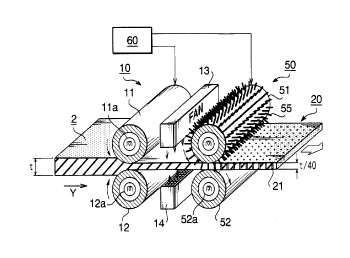
As shown in Fig. 2, a stretching roller pair 10 is
provided for stretching the film 20, including the upper and
lower rollers 11 and 12 faced with each other. A punching
roller pair 50 are provided for punching through-holes in
the film 20, including a needle roller 51 and a platen
roller 52 faced with each other. The stretching roller pair
10 and the punching roller pair 50 are disposed in parallel
to each other.
The upper roller 11 of the stretching roller pair 10 is
CA 02249~04 1998-10-06
rotated counterclockwise, while the lower roller 12 is
rotated clockwise. The needle roller 51 of the punching
roller pair 50 is rotated counterclockwise, while the platen
roller 52 is rotated clockwise. The stretching roller pair
5 10 and the punching roller pair 50 are driven by a common
driving mechanism 60 and rotated at the same circumferential
velocity.
The film 20 is inserted in a gap between the stretching
roller pair 10 in Y-direction. The upper and lower rollers
11 and 12 respectively have built-in heater lla and 12a and
heated at 150-C, which is higher than the shape-providing
temperature To of the shape memory resin of the film 20. The
film 20 is heated so that the film 20 exhibits a fluidized
states and pressed by the stretching roller pair 10, so that
15 the film 20 is stretched in Y-direction. The film 20 is
stretched so that the thickness of the film 20 is 0.03 to
0.08 mm (t/40). Since the film 20 is heated to a temperature
above the shape-providing temperature To, the thickness (0.03
to 0.08 mm) of the film 20 is maintained after the applied
20 head and pressure are removed.
A pair of fans 13 and 14 are located at downstream side
of the heat rollers 11 and 12. The film 20 which moves out
of the gap between the heat rollers 11 and 12 is rapidly
cooled by fans 13 and 14 to a temperature below the glass
25 transition temperature Tg. The purpose of the provision of
CA 02249~04 1998-10-06
the fans 13 and 14 is to cool the film 20 at least below the
shape providing temperature To immediately after the film 20
is stretched. Thus, it is prevented that a shape is
unintentionally given to the film 20 after the stretching.
S The punching roller pair 50 is disposed so that the
film 20 discharged from the stretching roller pair 10 is fed
into the punching roller pair 50. The needle roller 51 is
provided with needles planted throughout the outer surface
thereof. The needle 55 is long enough to penetrate the film
10 20. The film 20 is fed in a gap between the needle roller 51
and the platen roller 52. The needle roller 51 and the
platen roller 52 respectively have built-in heaters 51a and
52a and are heated at 70 C, which is higher than the glass
transition temperature Tg of the shape memory resin. The film
20 is heated so that the film 20 exhibits a rubber state
(that is, an elastic state). In this state, the film 20 is
pressed by the needle roller 51 and the platen roller 52.
The needles 55 planted on the outer surface of the
needle roller 50 pierce the film 20 (which is in the rubber
state), so that the through-holes 25 are punched in the film
20 by the needles 55. Since the axial length of the needle
roller 50 (covered by the needles 55) is the same as the
width of the film 20, the through-holes 25 are formed
throughout the surface of the film 20. The needle 55 is of a
diameter that permits the through-hole 25 to substantially
CA 02249~04 1998-10-06
close after formation. Since the film 20 is in an elastic
state, just after the needle 55 moves out of the through-
hole 25, the through-hole 25 is contracted and substantially
closed due to the elastic force.
The film 20 which moves out of the punching roller pair
50 is cooled by surrounding atmosphere, to a temperature
below the glass transition temperature Tg of the shape memory
resin. With this, the film 20 with through-hole 25 is
produced.
According to the above-described embodiment, the
stretching of the film 20 and the punching of the through-
holes 25 are performed by substantially one process shown in
Fig. 2. Thus, the whole process is simplified. Further,
since the stretching of the film 20 and the punching of the
through-holes 25 are performed by substantially one
apparatus shown in Fig. 2, the equipment for producing the
film with through-holes is simplified.
In the above-described producing method, if the
punching roller pair 50 is sufficiently apart from the
stretching roller pair 10 so that the temperature of the
film 20 (at the punching roller pair 50) is cooled by an
atmosphere to a temperature at least below the shape
providing temperature To/ it is not necessary to provide the
fans 13 and 14. Conversely, in case the fans 13 and 14 are
provided between the stretching roller pair 10 and the
CA 02249~04 1998-10-06
punching roller pair 50 as shown in Fig. 2, the distance
between the stretching roller pair 10 and the punching
roller pair 50 can be minimized.
In the above-described embodiment, it is possible to
form the through-holes 25 so that the through-holes 25 are
inclines with respect to the thickness of the film 20. In
such case, the needles 55 are provided to the needle roller
51 so that the needles 55 are inclined with respect to the
outer surface of the needle roller 50. Further, the needle
55 of the needle roller 51 can be replaced with projections.
Further, in a modification of the above-described
embodiment, the film 20 is made of a plastic such as
polytetrafluoroethylene (Teflon (trademark)). In such case,
the temperatures of the stretching roller pair 10 and the
punching roller pair 50 are determined according to the
heating characteristic of the plastic.
An ink transfer printer using the film 20 is described.
Fig. 4 is a sectional view of the ink transfer printer. The
ink transfer printer includes a thermal line head 3 having
multiple of heating elements 35 arranged in a row. The
above-described film 20 with through-holes (not shown in
Fig. 3) is supported by a board 3a of the thermal line head
3 via a spacer 8 provided therebetween, so that the film 20
and the thermal line head 3 are faced with each other.
-- 10 --
CA 02249~04 1998-10-06
The spacer 8 and the board 3a of the thermal line head
3 are made of materials which do not allow the permeation of
ink. Thus, ink is stored in a space surrounded by the spacer
8, the board 3a of the thermal line head 3 and the film 20.
A platen roller 4 is provided at the opposing side of the
film 20 with respect to the thermal line head 3, so that a
recording media R is sandwiched by the platen roller 4 and
the film 20. The circumferential surface of the platen
roller 4 is made of rubber. The rotation shaft 4a of the
platen roller 4 is orientated in a direction in which the
heating elements 35 of the thermal line head 3 are arranged.
When the platen roller 4 is rotated, the recording media R
is fed in the direction shown by an arrow in Fig. 4, due to
a traction between the recording media R and platen roller
4.
Fig. 5 is an exploded perspective view of the ink
transfer printer except the platen roller 4. The spacer 8 is
a thin plate member which surrounds the heating elements 35
of the thermal line head 3. That is, the spacer 8 defines
four side borders of the ink space 1 in which the heating
elements 35 are located. In order to supply ink to the ink
space 1, an ink tank 6 is provided on the board 3a of the
thermal line head 3 so that the ink tank 6 is adjacent to
the spacer 8. The ink tank 6 has a not-shown cavity in which
ink can be stored. Ink stored in the ink tank 6 is
CA 02249~04 1998-10-06
introduced into the ink space 1 through a slit-shaped outlet
opening 62 formed on the ink tank 6 and a slit-shaped
connecting opening 85 formed on the spacer 8, due to a
capillary action. The film 20 is attached to the upper
surface of the spacer 8 so that the through-holes 25 are
faced with the heating elements 35 of the thermal line head
3.
Figs. 6A and 6B are schematic views showing an ink
transferring process. As shown in Fig. 6A, the diameters of
the through-holes 25 are small so that ink does not permeate
the through-holes 25. The film 20 is almost in contact with
the heating element 35 of the thermal line head 3. When the
heating element 35 is heated, ink located in the vicinity of
the heating element 35 is heated. As shown in Fig. 6B, the
heated ink is vaporized and expanded, causing an increase in
the local pressure of ink. Also, a portion of the film 20
located in the vicinity of the heating element 35 is heated.
The elastic coefficient of the heated portion of the film 20
decreases, so that the heated portion of the film 20 is
easily deformed. Due to the increase in the local pressure
in ink, ink is pushed into the through-hole 25 of the film
20. Further, the through-hole 25 is widen so as to allow the
permeation of ink. With this, ink permeates the through-hole
25 and is transferred onto the recording media R (Fig. 4)
which is in contact with the upper surface of the film 20.
- 12 -
CA 02249~04 1998-10-06
After the heating of the heating elements 35 is stopped, the
heated ink is cooled by the surrounding ink, so that the
increase in the local pressure in ink disappears. Further,
the heated portion of the film is also cooled by ink. With
this, the widened through-holes 25 recover their original
diameters so that the through-holes 25 do not allow the
permeation of ink.
As constructed above, by controlling the thermal line
head 3 to selectively heat the heating elements 35 and by
rotating the platen roller 4 to feed the recording media R,
a desired image is formed on the recording media R.
In the above-described ink transfer printer, if the
glass transition temperature Tg of the film 20 is too high,
an energy consumption of the ink transfer printer may
increase. Conversely, if the glass transition temperature Tg
of the film 20 is too low, the through-holes 25 may
unintentionally open when the temperature of the environment
of the printer, particularly in summer. Thus, it is
preferable that the glass transition temperature Tg of the
film 20 is from 50 to 80 C (as long as the heating
temperature of the punching roller pair 50 shown in Fig. 2
is set to a temperature higher than the glass transition
temperature Tg of the film 20).
Although the producing apparatus and producing method
of a film with through-holes are described herein with
CA 02249~04 1998-10-06
respect to the preferred embodiment, many modifications and
changes can be made without departing from the spirit and
scope of the invention.
- 14 -