Language selection

Search

Patent 2249574 Summary

Third-party information liability

Some of the information on this Web page has been provided by external sources. The Government of Canada is not responsible for the accuracy, reliability or currency of the information supplied by external sources. Users wishing to rely upon this information should consult directly with the source of the information. Content provided by external sources is not subject to official languages, privacy and accessibility requirements.

Claims and Abstract availability

Any discrepancies in the text and image of the Claims and Abstract are due to differing posting times. Text of the Claims and Abstract are posted:

  • At the time the application is open to public inspection;
  • At the time of issue of the patent (grant).
(12) Patent Application: (11) CA 2249574
(54) English Title: DEVICE FOR HEATING PLASTICS PROFILE SECTIONS
(54) French Title: DISPOSITIF POUR CHAUFFER DES PROFILES EN PLASTIQUE
Status: Deemed Abandoned and Beyond the Period of Reinstatement - Pending Response to Notice of Disregarded Communication
Bibliographic Data
(51) International Patent Classification (IPC):
  • B29C 53/84 (2006.01)
  • B29B 13/02 (2006.01)
  • B29C 35/04 (2006.01)
  • B29C 53/02 (2006.01)
(72) Inventors :
  • HUGUET, PIERRE (France)
(73) Owners :
  • TECHNOPLAST KUNSTSTOFFTECHNIK GMBH
(71) Applicants :
  • TECHNOPLAST KUNSTSTOFFTECHNIK GMBH (Austria)
(74) Agent: MARKS & CLERK
(74) Associate agent:
(45) Issued:
(86) PCT Filing Date: 1997-04-30
(87) Open to Public Inspection: 1997-11-13
Availability of licence: N/A
Dedicated to the Public: N/A
(25) Language of filing: English

Patent Cooperation Treaty (PCT): Yes
(86) PCT Filing Number: PCT/AT1997/000084
(87) International Publication Number: AT1997000084
(85) National Entry: 1998-09-21

(30) Application Priority Data:
Application No. Country/Territory Date
96/05757 (France) 1996-05-03

Abstracts

English Abstract


The invention concerns a device for heating plastics profile sections, in
particular for heating PVC profile sections (35), the device comprising a box
for holding the profile section. Said box has a support plate (3), side panels
and a lid, as well as means for feeding hot air to one end face of the profile
section (35) so that it can flow internally and externally past the profile
section. Efficient operation is attained in that a return duct (21, 22, 23) is
provided for returning and reheating the air when it has flowed through or
around the profile section (35) in order to form a closed air circuit.


French Abstract

L'invention concerne un dispositif permettant de chauffer des profilés en plastique, notamment des profilés (35) en PVC, qui comprend une caisse destinée à contenir les profilés et comportant une plaque d'appui (3), des parois latérales et un couvercle. Ce dispositif comprend également des éléments servant à acheminer de l'air chaud sur une face du profilé (35) et de le faire circuler à l'intérieur et à l'extérieur du profilé. On parvient à un mode opératoire efficace du fait qu'il est prévu une gaine de reprise (21, 22, 23) pour faire revenir l'air et le chauffer à nouveau, après son passage à travers ou autour du profilé (35), afin de former un circuit d'air fermé.

Claims

Note: Claims are shown in the official language in which they were submitted.

-1-
CLAIMS
1. Device for heating plastics sections, in particular
sections made of PVC, comprising a cabinet (1) to accommodate a
section (35), which cabinet (1) has a supporting plate (3),
side walls (4) and a cover (5), as well as means for
introducing hot air at one end of the section (35), so that it
can flow past on the inside and outside of the section (35),
characterized in that a return duct (21, 22, 23) is provided
below the supporting plate (3) for the purpose of recirculating
and reheating the air after it has passed the section (35) on
the inside and outside, in order to form a closed air circuit,
and that said return duct (21, 22, 23) is connected on the two
short ends of the cabinet (1) with the space above the
supporting plate (3).
2. Device as claimed in Claim 1, characterized in that the
return duct (21, 22, 23), a heating element (18) and preferably
a fan (17) are arranged in the cabinet (1), below the
supporting plate (3).
3. Device as claimed in Claim 1 or 2, characterized in that
the supporting plate (3) is designed so as to be liftable.
4. Device as claimed in any of Claims 1 to 3, characterized
in that the cabinet (1) is provided on its upper side with an
upwardly opening cover (5) and a working surface (9).
5. Device as claimed in Claims 3 and 4, characterized in that
the supporting plate (3) is movable, i.e., between a lowered
position in which the section (35) to be heated is entirely
positioned within the cabinet (1), and a lifted position, in
which the supporting plate (3) is in the same plane with the
working surface (9).

-2-
6. Device as claimed in any of Claims 1 to 5, characterized
in that the side walls (4) of the cabinet (1) are provided with
discharge openings (7) directing hot air onto the section (35).
7. Device as claimed in any of Claims 1 to 6, characterized
in that the heating element (18) comprises electric resistors
(19).
8. Device as claimed in any of Claims 1 to 7, characterized
in that a metal filter (20) is provided in the cabinet (1) to
clean the recirculated air.
9. Device as claimed in any of Claims 1 to 8, characterized
in that a fan (17) is provided, which is dimensioned so as to
move air through the cabinet (1) at an average rate of 20 to 30
m/sec.
10. Device as claimed in any of Claims 1 to 9, characterized
in that means are provided for conducting a hot air stream
along the working surface (9) in order to heat said working
surface (9).
11. Device as claimed in any of Claims 3 to 10, characterized
in that the supporting plate (3) in its lifted position will
essentially seal the cabinet (1) towards the top.
12. Process for heating plastics sections, preferably sections
made of PVC, where hot air is passed in longitudinal direction
along the inside and outside of a section (35), characterized
in that the air is conducted in a closed loop and that the air
temperature at the beginning of a heating cycle is raised to a
level lying about 5 to 15 percent above the standard
temperature prevailing during the heating cycle.

Description

Note: Descriptions are shown in the official language in which they were submitted.


CA 02249~74 1998-09-21
DEVICE FOR HEATING PLASTICS SECTIONS
This invention relates to a device for heating plastics
sections, in particular sections made of PVC, the device
comprising a cabinet to accommodate a section, which cabinet
has a supporting plate, side walls and a cover, as well as
means for introducing hot air at one end of the section, so
that it can flow past on the inside and outside of the section.
Plastics sections are usually made by extrusion of PVC
material. Certain applications require bending of the sections
in order to obtain round forms, etc. Such processes are
frequently employed in making doors and windows. The change in
shape is achieved upon heating the section to a suitable
temperature. For this purpose an oil bath may be applied, in
which the section is heated to about 125~C. Although the
devices known in this context will permit rapid heating,
considerable effort and expense is required for the subsequent
cleaning work, when the oil has to be removed from the section.
For this reason devices of this type are avoided if possible.
In DE-B 11 66 451 a device for heating plastics sections is
decribed, where hot air is blown into and passed along a
section. Various air ducts and flow obstructions are utilized
for preferred heating of special parts of the section. Such
device is complex and demands a large input of energy.
US-A 3,706,824 is concerned with a device for heating and
bending lengths of pipe. In that case heating elements are
introduced into the pipe in order to heat the pipe from inside.
Such devices are not suitable for parts with more intricate
cross-sections.
It is an object of this invention to overcome the above
problems and to propose a device which will ensure rapid and

CA 02249~74 1998-09-21
efficient heating accompanied by simplicity of design and low
cost.
According to the invention this is achieved by providing a
return duct for recirculating and reheating the air after it
has passed through the section, in order to form a closed air
circuit. The configuration proposed by the invention will offer
a compact design where heat losses are largely eliminated and
very little energy is required.
It is provided in a preferred embodiment that the return duct,
a heating element and preferably a fan be arranged in the
cabinet, i.e., below the supporting plate. This will result in
a particularly compact design of the device.
Operation of the device, i.e., especially insertion and removal
of the sections to be heated, may be simplified by designing
the supporting plate so as to be liftable.
In a preferred variant the cabinet is provided on its upper
side with an upwardly opening cover and a working surface. In
this way the bending operation may be performed on the device
itself as soon as the section has been lifted.
The invention further relates to a process for heating plastics
sections, preferably sections made of PVC, where hot air is
passed in longitudinal direction along the inside and outside
of a section. The principal feature of this process is that the
air is conducted in a closed loop.
The invention will now be described further, with reference to
the accompanying drawings illustrating embodiments thereof, in
which
. .

CA 02249~74 1998-09-21
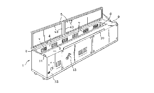
~igure 1 is an axonometric general view of the device proposed
by the invention,
Figure 2 is a longitudinal section through the device,
Figure 3 is a section along line III-III in Figure 2,
Figure 4 shows a detail of Figure 3,
Figure 5 is a section along line V-V in Figure 2.
The device comprises an elongated cabinet 1 which is designed
to accommodate a plastics section 35 ready for heating. To
permit accommodation of the different lengths of the sections
to be heated, the cabinet 1 may have a length of 4 m or more.
The cabinet 1 essentially is a parallelepiped and encloses a
heating compartment 2, which is closed off at the bottom by a
supporting plate 3 on which the sections 35 to be heated are
placed. On the upper side the cabinet 1 is closed by a hinged
cover 5 which can be opened in two parts, as is shown in Figure
1. Laterally, the heating compartment 2 is bounded by side
walls 4.
On one of its short ends the heating compartment 2 features an
opening 6 for introducing a stream of hot air, which is
expelled through another opening on the opposite end after
having passed the section 35.
As is also shown in Figure 1, the side walls 4 are provided
with openings or grids 7 permitting a lateral flow of hot air
to act on the sides of the section 35 to be heated.
The supporting plate 3 is movable in vertical direction in
order to facilitate insertion and removal of a section 35. On
the upper side of the cabinet 1 is provided a working surface 9
which forms part of the top of the cabinet 1. As a measure of
safety, the working surface 9 is bounded towards the front by a
projecting strip 10. Another projection 11 on the short end of

CA 02249~74 1998-09-21
- 4 -
the device is employed to hold the sections 35 upon heating,
for greater ease of operation.
To prevent the heated sections 35 on the working surface 9 from
cooling down too quickly, the working surface 9 may be heated
by a flow of hot air, which passes between the cover 5 and the
working surface 9.
On the front face of cabinet 1 display and control elements are
provided on a control panel 12. A crank 13 is provided for
lifting or lowering the supporting plate 3. As is seen from the
longitudinal section of Figure 2, the cabinet 1 is insulated
towards the outside. A bottom plate 15 is mounted on rollers
16. On the bottom plate 15 a fan 17 is positioned next to a
short end of cabinet 1, which fan 17 is dimensioned so as to
blow air through the cabinet 1 at a rate of 20-30 m/sec.
In a heating element 18, which also is mounted on bottom plate
15, a plurality of electric resistors 19 are provided. For
example, twelve resistors are used, each rated at 1 kW.
Upstream of resistors 19 is provided a metal filter 20 to
eliminate any contaminations of the air. The air circuit is
closed by collecting the air in a rigid return duct 21 once it
has flown past the section 35, and feeding it to the filter 20
through a flexible tube 22. Another flexible tube 23 will take
the air from the heating element 18 to the fan 17.
The supporting plate 3 on which the sections 35 are placed for
heating, is movable in vertical direction. In Figure 2 it is
presented in its lowered position, which is the standard
position assumed during the heating process. The supporting
plate 3 forms the lower side of the heating compartment 2. It
is borne by levers 25, which are supported on cabinet 1 on one
end via bearings 26. On the other end of the levers 25 are

CA 02249~74 1998-09-21
provided bearings 27, which will connect the levers 25 with the
supporting plate 3. By a swivel in anti-clockwise direction
(Figure 2) the supporting plate 3 is lifted. A spring 28 will
preload the levers 25 in this direction. Levers 25 will provide
a parallelogram linkage for the supporting plate 3. The axes
26a of bearings 26 and the axes 27a of bearings 27 are
horizontal and parallel to each other. Via a gear train not
shown here the crank 13 is linked with the levers 25 to permit
swivelling. As an alternative, the lever mechanism could be
driven by a motor.
In its lifted position a front end of the supporting plate 3 is
contiguous with the front wall 29 on a short end of cabinet 1,
as is indicated in Figure 2 by broken lines. In this way the
cabinet 1 is closed off on top even if covers 5 are open, which
will prevent any losses due to the escape of hot air. In the
lifted position the top of the supporting plate 3 is flush with
the working surface 9, such that the sections 35 can be handled
easily.
Above the fan 17 is provided a baffle box 31 for the hot air,
which is formed by a front wall 32 and a top wall 33. Walls 32
and 33 are thermally insulated.
Figure 3 presents a sectional view of cabinet 1 with the
supporting plate 3 lowered, whilst cover 5 is shown in open
position. As is seen, the heating compartment 2 is laterally
bounded by side walls 4. The heating compartment 2 may have a
cross-section of about 200 mm by 200 mm. Between the side walls
4 and the insulated walls 36 of cabinet 1 flow passages 37 are
provided to deliver hot air to the grids 7. These flow passages
37 may have a cross-section of 200 mm by 50 mm.
Figure 4 is a view of a detail from Figure 3. As is seen, the
sides of supporting plate 3 are provided with gaskets 38 which
.

CA 02249~74 1998-09-21
- 6 -
are mounted on a flange 39. Gaskets 38 serve to prevent the
escape of hot air between supporting plate 3 and side wall 4.
Figure 5 shows a cross-section through cabinet 1 at one of its
short ends, cover 5 being closed. The cover 5 is pivoted on a
hinge 40. At the side 41 opposite of hinge 40 a seal 43 is
provided on the lower side of the cover 5, which will seal the
cover 5 against the working surface 9. Because of the thickness
of the seal 43 a gap 42 is formed between the cover 5 and the
working surface 9, which is swept by a flow of hot air. This
will supply the working surface 9 with additional heat as the
hot air will spread over the entire width of the working
surface 9.
The hot air flow inside the heating compartment 2 is applied at
high speed, the specific working cycle employed depending on
the type of section 35 to be heated.
The working cycle will take several minutes. At the beginning
of the cycle the temperature is raised to a level of 5% to 15%
above normal heating temperature. During normal heating of the
sections 35, seventy-five percent of electrical resistors 19
are employed, whilst all of resistors 19 are utilized at the
beginning of the cycle.
Under normal heating conditions the air temperature will be
150~C, for example.
Means for heating the air are electrical resistors or other
suitable devices.

Representative Drawing
A single figure which represents the drawing illustrating the invention.
Administrative Status

2024-08-01:As part of the Next Generation Patents (NGP) transition, the Canadian Patents Database (CPD) now contains a more detailed Event History, which replicates the Event Log of our new back-office solution.

Please note that "Inactive:" events refers to events no longer in use in our new back-office solution.

For a clearer understanding of the status of the application/patent presented on this page, the site Disclaimer , as well as the definitions for Patent , Event History , Maintenance Fee  and Payment History  should be consulted.

Event History

Description Date
Inactive: IPC from MCD 2006-03-12
Time Limit for Reversal Expired 2002-04-30
Application Not Reinstated by Deadline 2002-04-30
Deemed Abandoned - Failure to Respond to Maintenance Fee Notice 2001-04-30
Inactive: Notice - National entry - No RFE 1999-10-18
Inactive: Applicant deleted 1999-10-18
Inactive: Filing certificate correction 1999-06-28
Letter Sent 1999-06-23
Inactive: Single transfer 1999-05-20
Inactive: Notice - National entry - No RFE 1999-01-13
Inactive: Applicant deleted 1999-01-13
Inactive: Filing certificate correction 1998-12-16
Classification Modified 1998-12-08
Inactive: First IPC assigned 1998-12-08
Inactive: IPC assigned 1998-12-08
Inactive: Courtesy letter - Evidence 1998-11-24
Inactive: Notice - National entry - No RFE 1998-11-19
Application Received - PCT 1998-11-16
Application Published (Open to Public Inspection) 1997-11-13

Abandonment History

Abandonment Date Reason Reinstatement Date
2001-04-30

Maintenance Fee

The last payment was received on 2000-03-31

Note : If the full payment has not been received on or before the date indicated, a further fee may be required which may be one of the following

  • the reinstatement fee;
  • the late payment fee; or
  • additional fee to reverse deemed expiry.

Patent fees are adjusted on the 1st of January every year. The amounts above are the current amounts if received by December 31 of the current year.
Please refer to the CIPO Patent Fees web page to see all current fee amounts.

Fee History

Fee Type Anniversary Year Due Date Paid Date
Basic national fee - small 1998-09-21
MF (application, 2nd anniv.) - small 02 1999-04-30 1999-04-15
Registration of a document 1999-05-20
MF (application, 3rd anniv.) - small 03 2000-05-01 2000-03-31
Owners on Record

Note: Records showing the ownership history in alphabetical order.

Current Owners on Record
TECHNOPLAST KUNSTSTOFFTECHNIK GMBH
Past Owners on Record
PIERRE HUGUET
Past Owners that do not appear in the "Owners on Record" listing will appear in other documentation within the application.
Documents

To view selected files, please enter reCAPTCHA code :


To view images, click a link in the Document Description column (Temporarily unavailable). To download the documents, select one or more checkboxes in the first column and then click the "Download Selected in PDF format (Zip Archive)" or the "Download Selected as Single PDF" button.

List of published and non-published patent-specific documents on the CPD .

If you have any difficulty accessing content, you can call the Client Service Centre at 1-866-997-1936 or send them an e-mail at CIPO Client Service Centre.

({010=All Documents, 020=As Filed, 030=As Open to Public Inspection, 040=At Issuance, 050=Examination, 060=Incoming Correspondence, 070=Miscellaneous, 080=Outgoing Correspondence, 090=Payment})


Document
Description 
Date
(yyyy-mm-dd) 
Number of pages   Size of Image (KB) 
Description 1998-09-20 6 241
Abstract 1998-09-20 1 18
Drawings 1998-09-20 3 70
Claims 1998-09-20 2 74
Representative drawing 1998-12-09 1 15
Notice of National Entry 1998-11-18 1 192
Reminder of maintenance fee due 1999-01-03 1 110
Notice of National Entry 1999-01-12 1 192
Courtesy - Certificate of registration (related document(s)) 1999-06-22 1 116
Notice of National Entry 1999-10-17 1 193
Courtesy - Abandonment Letter (Maintenance Fee) 2001-05-27 1 182
Reminder - Request for Examination 2002-01-01 1 117
PCT 1998-09-20 17 590
Correspondence 1998-11-23 1 30
Correspondence 1998-12-15 1 29
PCT 1998-11-23 6 173
Correspondence 1999-06-27 1 32