Sélection de la langue

Search

Sommaire du brevet 2249574 

Énoncé de désistement de responsabilité concernant l'information provenant de tiers

Une partie des informations de ce site Web a été fournie par des sources externes. Le gouvernement du Canada n'assume aucune responsabilité concernant la précision, l'actualité ou la fiabilité des informations fournies par les sources externes. Les utilisateurs qui désirent employer cette information devraient consulter directement la source des informations. Le contenu fourni par les sources externes n'est pas assujetti aux exigences sur les langues officielles, la protection des renseignements personnels et l'accessibilité.

Disponibilité de l'Abrégé et des Revendications

L'apparition de différences dans le texte et l'image des Revendications et de l'Abrégé dépend du moment auquel le document est publié. Les textes des Revendications et de l'Abrégé sont affichés :

  • lorsque la demande peut être examinée par le public;
  • lorsque le brevet est émis (délivrance).
(12) Demande de brevet: (11) CA 2249574
(54) Titre français: DISPOSITIF POUR CHAUFFER DES PROFILES EN PLASTIQUE
(54) Titre anglais: DEVICE FOR HEATING PLASTICS PROFILE SECTIONS
Statut: Réputée abandonnée et au-delà du délai pour le rétablissement - en attente de la réponse à l’avis de communication rejetée
Données bibliographiques
(51) Classification internationale des brevets (CIB):
  • B29C 53/84 (2006.01)
  • B29B 13/02 (2006.01)
  • B29C 35/04 (2006.01)
  • B29C 53/02 (2006.01)
(72) Inventeurs :
  • HUGUET, PIERRE (France)
(73) Titulaires :
  • TECHNOPLAST KUNSTSTOFFTECHNIK GMBH
(71) Demandeurs :
  • TECHNOPLAST KUNSTSTOFFTECHNIK GMBH (Autriche)
(74) Agent: MARKS & CLERK
(74) Co-agent:
(45) Délivré:
(86) Date de dépôt PCT: 1997-04-30
(87) Mise à la disponibilité du public: 1997-11-13
Licence disponible: S.O.
Cédé au domaine public: S.O.
(25) Langue des documents déposés: Anglais

Traité de coopération en matière de brevets (PCT): Oui
(86) Numéro de la demande PCT: PCT/AT1997/000084
(87) Numéro de publication internationale PCT: AT1997000084
(85) Entrée nationale: 1998-09-21

(30) Données de priorité de la demande:
Numéro de la demande Pays / territoire Date
96/05757 (France) 1996-05-03

Abrégés

Abrégé français

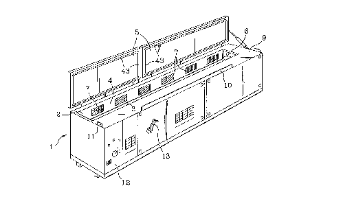
L'invention concerne un dispositif permettant de chauffer des profilés en plastique, notamment des profilés (35) en PVC, qui comprend une caisse destinée à contenir les profilés et comportant une plaque d'appui (3), des parois latérales et un couvercle. Ce dispositif comprend également des éléments servant à acheminer de l'air chaud sur une face du profilé (35) et de le faire circuler à l'intérieur et à l'extérieur du profilé. On parvient à un mode opératoire efficace du fait qu'il est prévu une gaine de reprise (21, 22, 23) pour faire revenir l'air et le chauffer à nouveau, après son passage à travers ou autour du profilé (35), afin de former un circuit d'air fermé.


Abrégé anglais


The invention concerns a device for heating plastics profile sections, in
particular for heating PVC profile sections (35), the device comprising a box
for holding the profile section. Said box has a support plate (3), side panels
and a lid, as well as means for feeding hot air to one end face of the profile
section (35) so that it can flow internally and externally past the profile
section. Efficient operation is attained in that a return duct (21, 22, 23) is
provided for returning and reheating the air when it has flowed through or
around the profile section (35) in order to form a closed air circuit.

Revendications

Note : Les revendications sont présentées dans la langue officielle dans laquelle elles ont été soumises.


-1-
CLAIMS
1. Device for heating plastics sections, in particular
sections made of PVC, comprising a cabinet (1) to accommodate a
section (35), which cabinet (1) has a supporting plate (3),
side walls (4) and a cover (5), as well as means for
introducing hot air at one end of the section (35), so that it
can flow past on the inside and outside of the section (35),
characterized in that a return duct (21, 22, 23) is provided
below the supporting plate (3) for the purpose of recirculating
and reheating the air after it has passed the section (35) on
the inside and outside, in order to form a closed air circuit,
and that said return duct (21, 22, 23) is connected on the two
short ends of the cabinet (1) with the space above the
supporting plate (3).
2. Device as claimed in Claim 1, characterized in that the
return duct (21, 22, 23), a heating element (18) and preferably
a fan (17) are arranged in the cabinet (1), below the
supporting plate (3).
3. Device as claimed in Claim 1 or 2, characterized in that
the supporting plate (3) is designed so as to be liftable.
4. Device as claimed in any of Claims 1 to 3, characterized
in that the cabinet (1) is provided on its upper side with an
upwardly opening cover (5) and a working surface (9).
5. Device as claimed in Claims 3 and 4, characterized in that
the supporting plate (3) is movable, i.e., between a lowered
position in which the section (35) to be heated is entirely
positioned within the cabinet (1), and a lifted position, in
which the supporting plate (3) is in the same plane with the
working surface (9).

-2-
6. Device as claimed in any of Claims 1 to 5, characterized
in that the side walls (4) of the cabinet (1) are provided with
discharge openings (7) directing hot air onto the section (35).
7. Device as claimed in any of Claims 1 to 6, characterized
in that the heating element (18) comprises electric resistors
(19).
8. Device as claimed in any of Claims 1 to 7, characterized
in that a metal filter (20) is provided in the cabinet (1) to
clean the recirculated air.
9. Device as claimed in any of Claims 1 to 8, characterized
in that a fan (17) is provided, which is dimensioned so as to
move air through the cabinet (1) at an average rate of 20 to 30
m/sec.
10. Device as claimed in any of Claims 1 to 9, characterized
in that means are provided for conducting a hot air stream
along the working surface (9) in order to heat said working
surface (9).
11. Device as claimed in any of Claims 3 to 10, characterized
in that the supporting plate (3) in its lifted position will
essentially seal the cabinet (1) towards the top.
12. Process for heating plastics sections, preferably sections
made of PVC, where hot air is passed in longitudinal direction
along the inside and outside of a section (35), characterized
in that the air is conducted in a closed loop and that the air
temperature at the beginning of a heating cycle is raised to a
level lying about 5 to 15 percent above the standard
temperature prevailing during the heating cycle.

Description

Note : Les descriptions sont présentées dans la langue officielle dans laquelle elles ont été soumises.


CA 02249~74 1998-09-21
DEVICE FOR HEATING PLASTICS SECTIONS
This invention relates to a device for heating plastics
sections, in particular sections made of PVC, the device
comprising a cabinet to accommodate a section, which cabinet
has a supporting plate, side walls and a cover, as well as
means for introducing hot air at one end of the section, so
that it can flow past on the inside and outside of the section.
Plastics sections are usually made by extrusion of PVC
material. Certain applications require bending of the sections
in order to obtain round forms, etc. Such processes are
frequently employed in making doors and windows. The change in
shape is achieved upon heating the section to a suitable
temperature. For this purpose an oil bath may be applied, in
which the section is heated to about 125~C. Although the
devices known in this context will permit rapid heating,
considerable effort and expense is required for the subsequent
cleaning work, when the oil has to be removed from the section.
For this reason devices of this type are avoided if possible.
In DE-B 11 66 451 a device for heating plastics sections is
decribed, where hot air is blown into and passed along a
section. Various air ducts and flow obstructions are utilized
for preferred heating of special parts of the section. Such
device is complex and demands a large input of energy.
US-A 3,706,824 is concerned with a device for heating and
bending lengths of pipe. In that case heating elements are
introduced into the pipe in order to heat the pipe from inside.
Such devices are not suitable for parts with more intricate
cross-sections.
It is an object of this invention to overcome the above
problems and to propose a device which will ensure rapid and

CA 02249~74 1998-09-21
efficient heating accompanied by simplicity of design and low
cost.
According to the invention this is achieved by providing a
return duct for recirculating and reheating the air after it
has passed through the section, in order to form a closed air
circuit. The configuration proposed by the invention will offer
a compact design where heat losses are largely eliminated and
very little energy is required.
It is provided in a preferred embodiment that the return duct,
a heating element and preferably a fan be arranged in the
cabinet, i.e., below the supporting plate. This will result in
a particularly compact design of the device.
Operation of the device, i.e., especially insertion and removal
of the sections to be heated, may be simplified by designing
the supporting plate so as to be liftable.
In a preferred variant the cabinet is provided on its upper
side with an upwardly opening cover and a working surface. In
this way the bending operation may be performed on the device
itself as soon as the section has been lifted.
The invention further relates to a process for heating plastics
sections, preferably sections made of PVC, where hot air is
passed in longitudinal direction along the inside and outside
of a section. The principal feature of this process is that the
air is conducted in a closed loop.
The invention will now be described further, with reference to
the accompanying drawings illustrating embodiments thereof, in
which
. .

CA 02249~74 1998-09-21
~igure 1 is an axonometric general view of the device proposed
by the invention,
Figure 2 is a longitudinal section through the device,
Figure 3 is a section along line III-III in Figure 2,
Figure 4 shows a detail of Figure 3,
Figure 5 is a section along line V-V in Figure 2.
The device comprises an elongated cabinet 1 which is designed
to accommodate a plastics section 35 ready for heating. To
permit accommodation of the different lengths of the sections
to be heated, the cabinet 1 may have a length of 4 m or more.
The cabinet 1 essentially is a parallelepiped and encloses a
heating compartment 2, which is closed off at the bottom by a
supporting plate 3 on which the sections 35 to be heated are
placed. On the upper side the cabinet 1 is closed by a hinged
cover 5 which can be opened in two parts, as is shown in Figure
1. Laterally, the heating compartment 2 is bounded by side
walls 4.
On one of its short ends the heating compartment 2 features an
opening 6 for introducing a stream of hot air, which is
expelled through another opening on the opposite end after
having passed the section 35.
As is also shown in Figure 1, the side walls 4 are provided
with openings or grids 7 permitting a lateral flow of hot air
to act on the sides of the section 35 to be heated.
The supporting plate 3 is movable in vertical direction in
order to facilitate insertion and removal of a section 35. On
the upper side of the cabinet 1 is provided a working surface 9
which forms part of the top of the cabinet 1. As a measure of
safety, the working surface 9 is bounded towards the front by a
projecting strip 10. Another projection 11 on the short end of

CA 02249~74 1998-09-21
- 4 -
the device is employed to hold the sections 35 upon heating,
for greater ease of operation.
To prevent the heated sections 35 on the working surface 9 from
cooling down too quickly, the working surface 9 may be heated
by a flow of hot air, which passes between the cover 5 and the
working surface 9.
On the front face of cabinet 1 display and control elements are
provided on a control panel 12. A crank 13 is provided for
lifting or lowering the supporting plate 3. As is seen from the
longitudinal section of Figure 2, the cabinet 1 is insulated
towards the outside. A bottom plate 15 is mounted on rollers
16. On the bottom plate 15 a fan 17 is positioned next to a
short end of cabinet 1, which fan 17 is dimensioned so as to
blow air through the cabinet 1 at a rate of 20-30 m/sec.
In a heating element 18, which also is mounted on bottom plate
15, a plurality of electric resistors 19 are provided. For
example, twelve resistors are used, each rated at 1 kW.
Upstream of resistors 19 is provided a metal filter 20 to
eliminate any contaminations of the air. The air circuit is
closed by collecting the air in a rigid return duct 21 once it
has flown past the section 35, and feeding it to the filter 20
through a flexible tube 22. Another flexible tube 23 will take
the air from the heating element 18 to the fan 17.
The supporting plate 3 on which the sections 35 are placed for
heating, is movable in vertical direction. In Figure 2 it is
presented in its lowered position, which is the standard
position assumed during the heating process. The supporting
plate 3 forms the lower side of the heating compartment 2. It
is borne by levers 25, which are supported on cabinet 1 on one
end via bearings 26. On the other end of the levers 25 are

CA 02249~74 1998-09-21
provided bearings 27, which will connect the levers 25 with the
supporting plate 3. By a swivel in anti-clockwise direction
(Figure 2) the supporting plate 3 is lifted. A spring 28 will
preload the levers 25 in this direction. Levers 25 will provide
a parallelogram linkage for the supporting plate 3. The axes
26a of bearings 26 and the axes 27a of bearings 27 are
horizontal and parallel to each other. Via a gear train not
shown here the crank 13 is linked with the levers 25 to permit
swivelling. As an alternative, the lever mechanism could be
driven by a motor.
In its lifted position a front end of the supporting plate 3 is
contiguous with the front wall 29 on a short end of cabinet 1,
as is indicated in Figure 2 by broken lines. In this way the
cabinet 1 is closed off on top even if covers 5 are open, which
will prevent any losses due to the escape of hot air. In the
lifted position the top of the supporting plate 3 is flush with
the working surface 9, such that the sections 35 can be handled
easily.
Above the fan 17 is provided a baffle box 31 for the hot air,
which is formed by a front wall 32 and a top wall 33. Walls 32
and 33 are thermally insulated.
Figure 3 presents a sectional view of cabinet 1 with the
supporting plate 3 lowered, whilst cover 5 is shown in open
position. As is seen, the heating compartment 2 is laterally
bounded by side walls 4. The heating compartment 2 may have a
cross-section of about 200 mm by 200 mm. Between the side walls
4 and the insulated walls 36 of cabinet 1 flow passages 37 are
provided to deliver hot air to the grids 7. These flow passages
37 may have a cross-section of 200 mm by 50 mm.
Figure 4 is a view of a detail from Figure 3. As is seen, the
sides of supporting plate 3 are provided with gaskets 38 which
.

CA 02249~74 1998-09-21
- 6 -
are mounted on a flange 39. Gaskets 38 serve to prevent the
escape of hot air between supporting plate 3 and side wall 4.
Figure 5 shows a cross-section through cabinet 1 at one of its
short ends, cover 5 being closed. The cover 5 is pivoted on a
hinge 40. At the side 41 opposite of hinge 40 a seal 43 is
provided on the lower side of the cover 5, which will seal the
cover 5 against the working surface 9. Because of the thickness
of the seal 43 a gap 42 is formed between the cover 5 and the
working surface 9, which is swept by a flow of hot air. This
will supply the working surface 9 with additional heat as the
hot air will spread over the entire width of the working
surface 9.
The hot air flow inside the heating compartment 2 is applied at
high speed, the specific working cycle employed depending on
the type of section 35 to be heated.
The working cycle will take several minutes. At the beginning
of the cycle the temperature is raised to a level of 5% to 15%
above normal heating temperature. During normal heating of the
sections 35, seventy-five percent of electrical resistors 19
are employed, whilst all of resistors 19 are utilized at the
beginning of the cycle.
Under normal heating conditions the air temperature will be
150~C, for example.
Means for heating the air are electrical resistors or other
suitable devices.

Dessin représentatif
Une figure unique qui représente un dessin illustrant l'invention.
États administratifs

2024-08-01 : Dans le cadre de la transition vers les Brevets de nouvelle génération (BNG), la base de données sur les brevets canadiens (BDBC) contient désormais un Historique d'événement plus détaillé, qui reproduit le Journal des événements de notre nouvelle solution interne.

Veuillez noter que les événements débutant par « Inactive : » se réfèrent à des événements qui ne sont plus utilisés dans notre nouvelle solution interne.

Pour une meilleure compréhension de l'état de la demande ou brevet qui figure sur cette page, la rubrique Mise en garde , et les descriptions de Brevet , Historique d'événement , Taxes périodiques et Historique des paiements devraient être consultées.

Historique d'événement

Description Date
Inactive : CIB de MCD 2006-03-12
Le délai pour l'annulation est expiré 2002-04-30
Demande non rétablie avant l'échéance 2002-04-30
Réputée abandonnée - omission de répondre à un avis sur les taxes pour le maintien en état 2001-04-30
Inactive : Notice - Entrée phase nat. - Pas de RE 1999-10-18
Inactive : Demandeur supprimé 1999-10-18
Inactive : Correction au certificat de dépôt 1999-06-28
Lettre envoyée 1999-06-23
Inactive : Transfert individuel 1999-05-20
Inactive : Notice - Entrée phase nat. - Pas de RE 1999-01-13
Inactive : Demandeur supprimé 1999-01-13
Inactive : Correction au certificat de dépôt 1998-12-16
Symbole de classement modifié 1998-12-08
Inactive : CIB en 1re position 1998-12-08
Inactive : CIB attribuée 1998-12-08
Inactive : Lettre de courtoisie - Preuve 1998-11-24
Inactive : Notice - Entrée phase nat. - Pas de RE 1998-11-19
Demande reçue - PCT 1998-11-16
Demande publiée (accessible au public) 1997-11-13

Historique d'abandonnement

Date d'abandonnement Raison Date de rétablissement
2001-04-30

Taxes périodiques

Le dernier paiement a été reçu le 2000-03-31

Avis : Si le paiement en totalité n'a pas été reçu au plus tard à la date indiquée, une taxe supplémentaire peut être imposée, soit une des taxes suivantes :

  • taxe de rétablissement ;
  • taxe pour paiement en souffrance ; ou
  • taxe additionnelle pour le renversement d'une péremption réputée.

Les taxes sur les brevets sont ajustées au 1er janvier de chaque année. Les montants ci-dessus sont les montants actuels s'ils sont reçus au plus tard le 31 décembre de l'année en cours.
Veuillez vous référer à la page web des taxes sur les brevets de l'OPIC pour voir tous les montants actuels des taxes.

Historique des taxes

Type de taxes Anniversaire Échéance Date payée
Taxe nationale de base - petite 1998-09-21
TM (demande, 2e anniv.) - petite 02 1999-04-30 1999-04-15
Enregistrement d'un document 1999-05-20
TM (demande, 3e anniv.) - petite 03 2000-05-01 2000-03-31
Titulaires au dossier

Les titulaires actuels et antérieures au dossier sont affichés en ordre alphabétique.

Titulaires actuels au dossier
TECHNOPLAST KUNSTSTOFFTECHNIK GMBH
Titulaires antérieures au dossier
PIERRE HUGUET
Les propriétaires antérieurs qui ne figurent pas dans la liste des « Propriétaires au dossier » apparaîtront dans d'autres documents au dossier.
Documents

Pour visionner les fichiers sélectionnés, entrer le code reCAPTCHA :


Pour visualiser une image, cliquer sur un lien dans la colonne description du document (Temporairement non-disponible). Pour télécharger l'image (les images), cliquer l'une ou plusieurs cases à cocher dans la première colonne et ensuite cliquer sur le bouton "Télécharger sélection en format PDF (archive Zip)" ou le bouton "Télécharger sélection (en un fichier PDF fusionné)".

Liste des documents de brevet publiés et non publiés sur la BDBC .

Si vous avez des difficultés à accéder au contenu, veuillez communiquer avec le Centre de services à la clientèle au 1-866-997-1936, ou envoyer un courriel au Centre de service à la clientèle de l'OPIC.

({010=Tous les documents, 020=Au moment du dépôt, 030=Au moment de la mise à la disponibilité du public, 040=À la délivrance, 050=Examen, 060=Correspondance reçue, 070=Divers, 080=Correspondance envoyée, 090=Paiement})


Description du
Document 
Date
(aaaa-mm-jj) 
Nombre de pages   Taille de l'image (Ko) 
Description 1998-09-20 6 241
Abrégé 1998-09-20 1 18
Dessins 1998-09-20 3 70
Revendications 1998-09-20 2 74
Dessin représentatif 1998-12-09 1 15
Avis d'entree dans la phase nationale 1998-11-18 1 192
Rappel de taxe de maintien due 1999-01-03 1 110
Avis d'entree dans la phase nationale 1999-01-12 1 192
Courtoisie - Certificat d'enregistrement (document(s) connexe(s)) 1999-06-22 1 116
Avis d'entree dans la phase nationale 1999-10-17 1 193
Courtoisie - Lettre d'abandon (taxe de maintien en état) 2001-05-27 1 182
Rappel - requête d'examen 2002-01-01 1 117
PCT 1998-09-20 17 590
Correspondance 1998-11-23 1 30
Correspondance 1998-12-15 1 29
PCT 1998-11-23 6 173
Correspondance 1999-06-27 1 32