Note: Descriptions are shown in the official language in which they were submitted.
CA 02249707 1998-10-29
14-543
SUBMERGED ENTRY NOZZLE
Field of the Invention
The present invention relates to a submerged entry nozzle
for introducing molten steel into a continuous casting mold, and
more particularly to the structural configuration of the
S submerged entry nozzle.
Background Art
In the continuous casting of steel, molten steel is
delivered to a mold by means of a refractory tube which is
submerged in the liquid steel. This refractory tube is referred
to as a submerged entry nozzle and, in the case of slab casters,
includes a central bore that terminates into two exit ports that
extend transverse to the central bore. The purpose of the
submerged entry nozzle is to prevent reoxidation of the steel.
Aluminum is added to the molten steel to remove oxygen. While
this may reduce or eliminate oxygen, it also has the undesirable
side-effect of possibly clogging the passages of the nozzle with
accretions of aluminum oxide. In conventional casting methods,
nitrogen gas, argon gas or a mixture of the two gases is injected
into the nozzle.during casting to scrub the build up of
accretions of aluminum oxide on the inside of the passages and to
prevent non-metallic inclusions from adhering to the inside of
the nozzle.
In the mold, a liquid slag layer is formed on the steel
meniscus by adding or distributing mold powder into the mold on
top of the molten steel. This liquid slag layer acts as both a
1
CA 02249707 1998-10-29
c s
.. ~. _
lubricant in that it flows into the gaps between the solidifying
steel shell and the mold as the molten steel solidifies, and as
an insulator in that it inhibits heat from escaping the meniscus
of the liquid steel.
To ensure an adequately thick slag layer, and thereby
prevent the freezing of the steel near the meniscus, the
temperature of the steel near the meniscus must be maintained
sufficiently high. This is attained in conventional casting by
the injection of argon gas into the submerged entry nozzle. The
argon gas affects buoyancy in the liquid'steel so that as the
steel exits the exit ports of the nozzle it tends to rise towards
the meniscus and therefore maintain a temperature sufficient to
withstand freezing.
A deficiency in the production of molten steel and, in
particular, ultra low carbon (ULC) and low carbon steel for
exposed automotive applications, is the so-called pencil pipe
defect. Pencilpipe defects arise from the entrapment of
agglomerates of non-metallic inclusions and bubbles of argon gas
under the solidifying shell of the steel being cast_ The steel
emerges from the caster in the form of a slab which is rolled
down to a thin strip and collected as a coil. During subsequent
processing of the strip the gas bubbles trapped under.the skin of
the strip, but now much closer to its surface, expand and form a
blister on the surface of the finished product_ Therefore, while
use of argon gas reduces clogging, improves the slag layer
thickness and increases the temperature near the meniscus, it
2
s
CA 02249707 1998-10-29
,. ~. _
also causes the undesirable pencil pipe defect due to trapped
agglomerates of gas bubbles and inclusions.
The number of pencil pipe defects can be eliminated or
substantially reduced by eliminating the injection of argon gas
into the nozzle. However, in the absence of argon gas injection,
it has been found in practice that there is a reduction in the
slag layer thickness and, consequently, an increased risk that
the steel near the meniscus will freeze. This can lead to the
formation of surface defects known as "slivers".
These undesirable side-effects can be avoided, or their
occurrence substantially reduced, by appropriately modifying the
structure o.f the submerged entry nozzle, which is the object of
the present invention.
Summary of the Invention
The present invention provides a submerged entry nozzle for
ensuring adequate slag layerthickness and heat delivery to the
meniscus, whereby pencil pipe defects and slivers are minimized.
According to the invention, the temperature near the meniscus is
sufficiently high as to prevent the freezing of the steel at the
meniscus in the absence of argon gas injection, or at rates of
gas injection lower than that employed by conventional nozzles.
It also ensures that the turbulence at the meniscus is not
increased to a point that slag particles are entrained into the
liquid steel stream.
The submerged entry nozzle includes nozzlestructure that
defines a central bore extending vertically through the
3
CA 02249707 1998-10-29
.. ,.
structure. The central bore terminates at an upwardly dish-
shaped bottom surface. The upwardly dish-shaped surface directs
the flow of molten steel through two exit ports about 180 degrees
apart. The exit ports are partially defined at an upper region
by downwardly slanted lips and at a lower region by the upwardly
dish-shaped bottom surface. Unlike prior nozzles that direct the
flow of steel in a generally downward direction as it exits the
nozzles, the dish-shaped bottom surface in combination with the
downwardly slanted lips directs the exit flow of steel in a
direction close to the horizontal_ As a-result, a greater
portion of the steel turns up towards the meniscus in a shorter
amount of time.
According to a feature of the invention, the upwardly dish-
shaped bottom surface is positively sloped at about an angle of 5
to 35 degrees with respect to a plane perpendicular to the
vertically extending central bore. According to another feature
of the invention, the downwardly slanted lips are negatively
sloped at about an angle of 5 to 35 degrees with respect to a
plane perpendicular to the vertically extending central bore.
Additional features will become apparent and a fuller
understanding obtained by reading the following detailed
description made in connection with the accompanying drawings.
Brief Description of the Drawings
Figure 1 is a vertical cross-sectional view of a submerged
entry nozzle constructedin accordance with the present
invention;
4
CA 02249707 1998-10-29
- ,_
Figure 2 is a side elevational view of the nozzle shown in
Figure 1;
Figure 3 is a bottom view of the nozzle shown in Figure l;
Figure 4 is a fragmentary, cross-sectional view of the
bottom end of the nozzle of Figure 1 showing the flow path of
molten steel as it issues from the nozzle;
Figure 5A is a fragmentary, cross-sectional view of the
bottom end of a conventional nozzle showing the flow path of
molten steel as it issues from the nozzle;
Figure 5B is a fra
gmentary, cross-sectional view of the
bottom end of a conventional nozzle showing the flow path of
molten steel as it issues from the nozzle;
Figure 5C is a fragmentary, cross-sectional view of the
bottom end of a conventional nozzle showing the flow path of
~-5 molten steel as it issues from the nozzle;
Figure 6 is a graph showing a velocity profile in the upper
portion of a mold of the nozzle shown in Figure 1;
Figure 7 is a graph showing a velocity profile in the upper
portion of a mold of a conventional nozzle;
Figure 8 illustrates a double roll flow pattern of molten
steal in a mold with a conventional nozzle;
Figure 9 illustrates entrapment of argon inclusion
agglomerates under the solidifying shell and curvature of the
curved mold inner radius; and
Figure 10 is a graph showing the thermal response in the
meniscus of a steel mold that compares a conventional nozzle with
5
CA 02249707 1998-10-29
the submerged entry nozzle constructed in accordance with the
present invention.
Best Mode fQr P~actic~.ncr the Invention
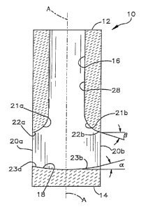
Figures 1-3 illustrate a submerged entry nozzle 10 for
introducing molten steel into a casting mold. The nozzle 10 is
constructed of generally tubular-shaped refractory material and
includes a-top end 12 adapted to connect to a tundish and a
bottom end 14 that is submerged into the casting mold. A
generally circular central bore 16 extends vertically and
concentrically through the nozzle 10, the center of which is
defined by the geometric center of the nozzle 10, indicated
generally by the axis A-A.
As shown in Figures 1 and 3, the central bore 16 terminates
at a dish-shaped bottom surface 18 that extends to the periphery
of the nozzle 10 and is in fluid communication with a pair of
exit ports 20a, 20b that extend transverse to the central bore
16. In the preferred embodiment, the exit ports 20a, 20b are
about 180 degrees apart (as shown in Figure 3). The exit ports
20a, 20b comprise upper regions 21a, 21b and lower regions 23a,
23b. The upper regions 21a, 21b are partially defined by
respective downwardly slanted lips 22a, 22b. The lips 22a, 22b
sweep from an interior wall 28 of the central bore 16 to the
periphery or outer wall of the nozzle 10. The lower regions 23a,
23b of the exit ports 20a, 20b are partially defined by the dish-
shaped bottom surface 18. The dish-shaped bottom surface 18 is
6
CA 02249707 1998-10-29
3 ~ _
curved outwardly and upwardly from axis A-A to the periphery of
the nozzle 10. Accordingly, the bottom surface 18 is positively
sloped at an angle alpha with respect to a horizontal plane
perpendicular to axis A-A. The lips 22a, 22b, on the other hand,
are negatively sloped at an angle beta with respect to the
horizontal plane.
According to the invention, the angles alpha and beta can
vary between five and 35 degrees- The desired angle may depend
on such factors as the size of the nozzle, the casting speed, the
immersion depth of the nozzle and other features particular to a
given caster design. In a preferred embodiment, angles alpha and
beta are 15 degrees from the horizontal.
Figure 4 shows the flow path of liquid steel as it issues
from the exit ports 20a, 20b of the entry nozzle 10_ According
to the invention, as liquid steel flows through the central bore
16 and the exit ports 20a, 20b, the upper regions 21a, 21b direct
the flow of steel downward from the horizontal, while the lower
regions 23a, 23b direct the steel in an upward direction that
collides with, or impinges upon, a portion of the flow directed
from the upper regions 21a, 21b.
These flow characteristics provide several advantages over
conventional submerged nozzles. By way of comparison, the
conventional nozzles illustrated in Figures 5A, 5B and 5C are
characterized by a well 111, some of which are partially dished
(Figures 5B and 5C), in the bottom end of the nozzle. In none of
these known prior art nozzles does the well 111 extend to the
7
CA 02249707 1998-10-29
periphery of the nozzle as it does in the disclosed invention.
In addition, the prior art nozzles 110 illustrated in Figures 5A,
5B, and 5C are characterized by exit ports 120a, 120b having
outwardly and downwardly sloped surfaces 123a, 123b. This
results in the exit ports 120a, 120b directing the liquid stream
in a generally downward direction from the horizontal in the
vicinity of the exit ports 120a, 120b, as is represented by the
arrows in Figures 5A, 5B, and 5C. This effects a concentrated
and turbulent flow path in the liquid steel as it exits the
nozzle 110.
Unlike conventional nozzles 110, the dish-shaped bottom
surface 18 of the present invention extends outwardly and
upwardly atthe periphery of the nozzle 10, thereby directing the
flow of liquid steel upwardly from the horizontal in the vicinity
of the exit ports 20a, 20b, as is represented by the arrows in
Figure 4. Consequently, a greater portion of the liquid steel is
directed towards the meniscus than what conventional nozzles have
achieved. A comparison of the flow paths shown in Figure 4 and
Figures 5A, 5B and 5C shows that the flow path of the liquid
steel issuing from the nozzle 10 of the present invention is
substantially more horizontal compared to that for the
conventional nozzle 110. This effects a quiescent flow path
which reduces turbulence at the meniscus and, therefore, reduces
the likelihood of entraining molten slag into the liquid steel
stream.
The submerged entry nozzle 10 establishes a flow pattern in
8
CA 02249707 1998-10-29
the casting mold that promotes heat delivery to the meniscus at a
substantially improved rate over that which conventional nozzles
have been able to attain without argon injection. This ensures
that the temperature of the steel near the meniscus will be
sufficiently high for melting the mold powder and thereby
providing a sufficiently uniformly thick mold slag layer-for
absorbing impurities and serving as a lubricant between the
caster and the mold as the molten steel solidifies.
Some prior art nozzles have relied on argon gas injection in
the nozzle to achieve higher temperatures near the meniscus of
the molten cast, whereby the argon gas buoyantly directs the
molten steel towards the meniscus. The flow characteristics of
the present invention eliminate or substantially reduce the need
for argon gas injection. By eliminating the use of argon
injection, the present invention reduces the likelihood of pencil
pipe defects caused by bubbles of argon gas remaining under the
solidifying shell of the molten cast. Furthermore, since the
flow path of the present invention generates higher temperatures
near the meniscus than what conventional nozzles have achieved,
it is less likely that freezing of the molten steel near the
meniscus will occur. Consequently, there is a reduced likelihood
of the surface defects known as "slivers."
Experiments were conducted to demonstrate the advantages of
the flow characteristics of the submerged entry nozzle 10 of the
present invention over those of the conventional nozzles 110
shown in Figure 5A. Specifically, water model simulations were
9
CA 02249707 1998-10-29
performed on a 0.4 scale water model caster. Velocity profiles
in the water models were measured using a Particle Image
Velocimetry (PIV) technique.
Figures 6 and 7 represent vertical planes in the liquid
5. steel mold (the planes being parallel to the plane of the page)
showing the velocity vectors of the liquid steel exiting the
respective nozzles 10, 110 in the upper portion of the mold. The
right portion of each figure represents a vertical plane
(perpendicular to the plane of the page) through which axis A-A
of the nozzle Lies. The left most portion of each figure
represents a vertical plane (perpendicular to the plane of the
page) that.is about 600 of the distance from axis A-A of the
nozzle to the edge (not shown) of the mold; the edge being the
narrow face in a 73-inch wide mold_ Gas injection was absent in
both nozzle experiments. The casting speed was about 50 inches
per minute and the immersion depth of each nozzle was about six
inches.
It was found that the exit ports 120a, 120b of the
conventional nozzle 110 directed the water downwardly at an angle
(generally indicated by arrow 140 in Figure 7).steeper than what
was experienced by the nozzle 10 of the present invention
(generally indicated by arrow 40 in Figure 6). Consequently, the
liquid. steel stream from the nozzle 10 of the present invention
experiences a shallower penetration depth than that of the
conventional nozzle 110.
As shown in Figure 8, the li-quid steel issuing from the
CA 02249707 1998-10-29
conventional nozzle 110 impinges on the narrow face and separates
into two paths, known in the art as the double roll pattern. One
portion flows upwardly along the narrow face and then returns
along the meniscus and towards the nozzle 110. The other portion
flows downwardly and also returns towards the nozzle 110. The
double roll flow pattern results in a standing wave profile,
causing a nonuniform thickness of the mold slag layer whereby the
mold slag is relatively thinner near the narrow face than at or
around the nozzle 110.
The deep penetration of the liquid steel stream from the
conventional nozzle 110 also increases penetration of argon gas
inclusion agglomerates or bubbles deep into the molten steel
pool. As is generally shown in Figure 9, attempts of the argon
gas to float upward are inhibited by the entrapment of the argon
inclusion agglomerates under the solidifying shell of the inner
radius of the curved mold_ Subsequent processing of the steel,
e.g. annealing, results in the pencil pipe defect by the
entrapped gas bubbles expanding and forming blisters on the
surface of the rolled product.
Referring now to Figure 6, it is seen that the flow profile
of the liquid steel issuing from the nozzle 10 of the present
invention is substantially more horizontal compared to that for
the conventional nozzle 110-shown in Figure 7. Consequently, the
liquid steel penetration depth is lower and argon inclusion
2S agglomerates penetrate to a lesser distance below the curvature
of the curved mold inner radius. Therefore, the likelihood of
11
CA 02249707 1998-10-29
v
the argon inclusion agglomerates getting entrapped under the
inner radius and later forming pencil pipe defects is
substantially reduced_
It is also seen that the steel velocity near the meniscus is
substantially lower for the nozzle 10 of the-present invention
than it is for the conventional nozzle 110. This reduces the
likelihood ref entraining particles from the mold slag layer into
the recirculating liquid stream in the mold and later causing
defects such as slivers or pencil pipe. This was confirmed by
water modeling tests in which silicon oil. was used to simulate
the mold slag. The tests showed that under conditions of no gas
injection, the nozzle 10 of the present invention produced a calm
and flat meniscus (in contrast to the standing wave profile of
the conventional nozzle 110) even at casting speeds as high as 60
inches/min. The conventional nozzle 110, on the other hand,
started entraining slag at casting speeds below 45 inches/min.
It is therefore believed that by use of the submerged entry
nozzle 10 of -the present invention casting can be performed at
higher speeds than those attained by use of the conventional
nozzle 110. Consequently, the overall productivity of the caster
is substantially improved_
Figure 6 shows that, unlike the conventional nozzle 110
wherein the molten steel stream does not flow towards the
meniscus until the stream first impinges on the narrow face, the
nozzle 10 of the present invention dir~ct~ portions of the molten
steel stream towards the meniscus shortly after the steel exits
12
CA 02249707 1998-10-29
r
the nozzle 10. The upper left corner of Figure 6 shows that the
meniscus-directed flow begins when the steel from the submerged
entry nozzle 10 has reached only about 40% of the distance from
the nozzle 10 to the narrow face. Thus, the liquid steel
discharged from the exit ports 20a, 20b of the nozzle 10 of the
present invention is directed towards the meniscus sooner than
the steel discharged from the exit ports 120a, 120b of the
conventional nozzle 110_ Therefore, even though the nozzle 10 of
the present invention reduces the velocity of the molten steel in
the meniscus region, the heat from the incoming liquid steel
stream is delivered to the meniscus in sufficient enough time
that the temperature of the meniscus is sufficiently high to melt
the mold powder and provide proper lubrication for casting.
Water model tests were conducted on the nozzles 10, 110 to
demonstrate-that the nozzle 10 of the present invention could-
deliver adequate heat to the meniscus at the same or an improved
rate as the conventional nozzle 110. Hot water was delivered
through the respective nozzles 10, 110 into a relatively cooler
(room temperature) pool of water representing the liquid steel in
the mold. The temperature response was measured and averaged for
each nozzle 10, 110 over a range of points at the meniscus.
Figure 10 shows an example of a comparison of the
temperature at the meniscus between the nbzzle 10 of the present
invention with no argon gas injection and the conventional nozzle
110 with 5 liters per minute of gas injection. The ability of
the flow paths of the respective nozzles 10, 110 to deliver
13
CA 02249707 1998-10-29
sufficient heat to a particular point at the meniscus is
indicated by the initial rise in the temperature in the 20 to 30
second range_ As Figure 10 shows, the thermal response of the
nozzle 10with no argon gas injection is similar to that of the
conventional nozzle 110 with 5 liters per minute of argon gas
injection.
Although the present invention has been described with a
certain degree of particularity, it should be understood that
those skilled in the art can make various changes to it without
departing from the spirit or scope of the invention as
hereinafter claimed_
14